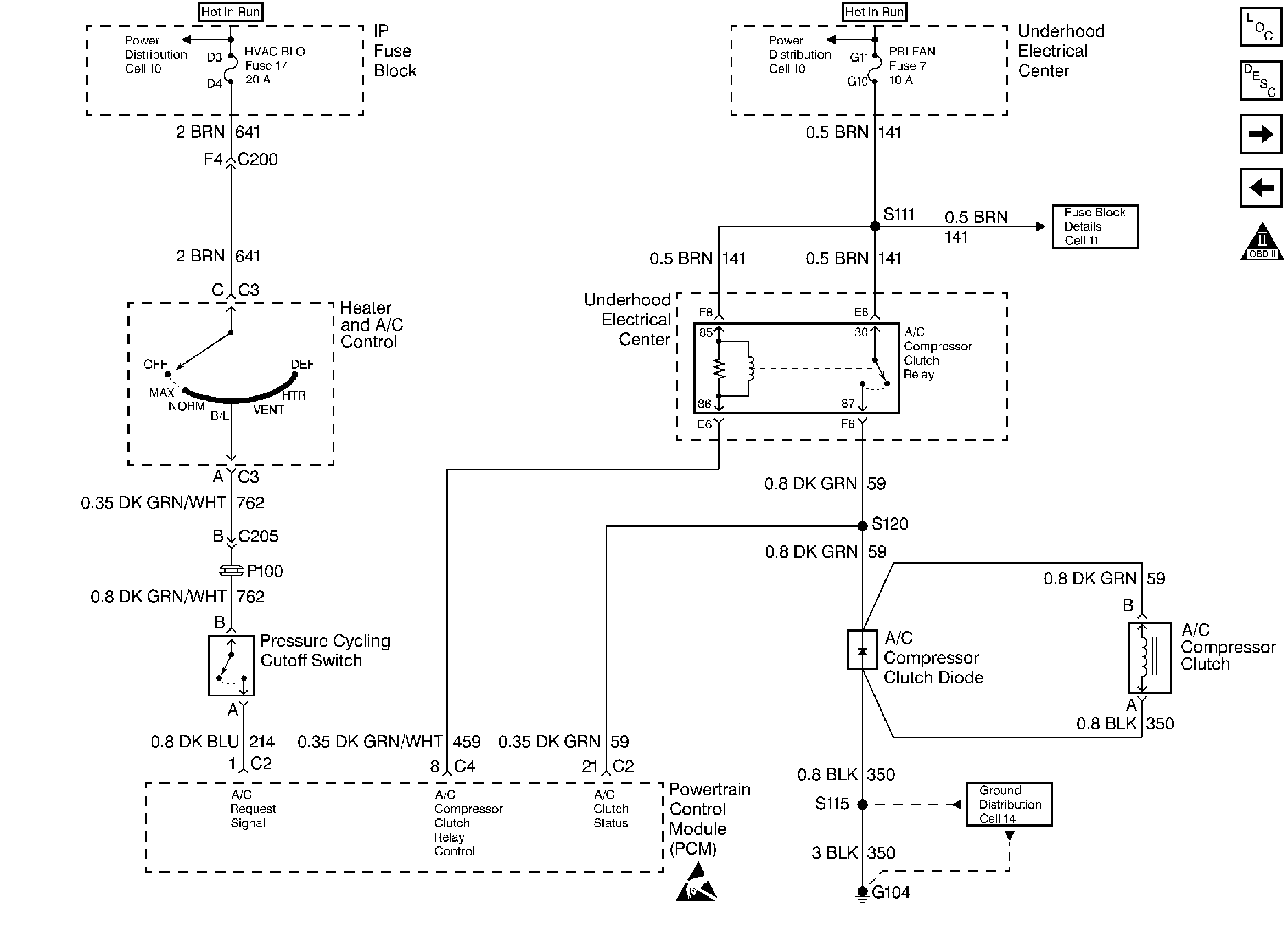
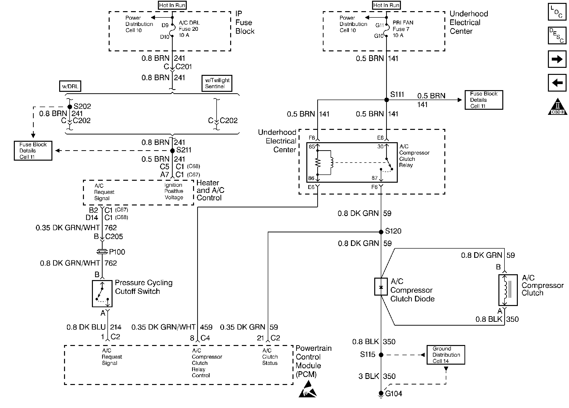
Circuit Description:
The A/C clutch relay is PCM controlled to delay A/C clutch engagement after the A/C is turned ON. This allows the PCM to adjust engine RPM before the A/C clutch engages. The PCM will engage the A/C clutch any time A/C has been requested unless any of the following conditions exist:
| • | High coolant temperature. |
| • | Low A/C system pressure. |
| • | High A/C system pressure. |
| • | Wide open throttle. |
| • | High engine RPM. |
When the heater and A/C control is placed in the A/C mode, a 12 volt signal is sent to the PCM. When the PCM receives this signal the PCM will ground the A/C clutch relay control circuit to energize the A/C relay. This is shown on the scan tool as A/C request YES.
When a request for A/C has been detected by the PCM, the PCM will ground the A/C clutch relay control circuit, the relay contacts will close, and current will flow through the relay to the A/C compressor clutch.
When A/C request has been detected by the PCM, the cooling fan(s) will
be turned ON when A/C pressure is above a predetermined pressure. For the
system schematic, refer to
A/C Controls - C60

or
A/C Controls - C67 and C68

.
Diagnostic Aids
Before using this table, be sure no PCM DTC(s) are stored. The PCM will not activate the A/C clutch with a stored DTC.
Test Description
Number(s) below refer to number(s) on the diagnostic table.
-
A/C DTCs will disable the A/C system. Repair A/C DTCs before proceeding.
-
If the scan tool displays A/C request as YES, indicates the request circuit is shorted to a voltage.
-
If the test light did not illuminate, indicates a problem with the request circuit between the A/C pressure switch and the control head or the control head is malfunctioning. Refer to Repair Procedures in Electrical Diagnosis (8A Cell 67).
Step | Action | Value(s) | Yes | No |
|---|---|---|---|---|
1 | Was the Powertrain On-Board Diagnostic (OBD) System Check performed? | -- | ||
Are any A/C DTCs set? | -- | Go to applicable DTC table. | ||
Does the scan tool indicate A/C request as YES? | -- | |||
4 | Turn the ignition ON and A/C ON. Does the scan tool indicate A/C request as YES? | -- | Go to Symptoms | |
Does the DVM display near the specified voltage? | B+ | Go to Repair Procedures in Electrical Diagnosis (8A Cell 67). | ||
6 | Using a fused jumper wire, jumper terminals A and B together at the A/C pressure cycling switch harness connector. Does the scan tool indicate A/C request as YES? | -- | ||
7 |
Is the A/C request circuit open? | -- | ||
8 | Is the A/C request circuit shorted to ground? | -- | ||
9 | Disconnect the A/C pressure cycling switch. Does the scan tool indicate A/C request as YES? | -- | Go toRepair Procedures in Electrical Diagnosis (8A Cell 67). | |
10 | Using a test light connected to ground, probe the A/C request circuit at the A/C pressure cycling switch harness connector (PCM side). Does the test light illuminate? | -- | ||
11 | Repair the A/C request circuit for a short to voltage. Refer to Repair Procedures in Electrical Diagnosis (8A Cell 5). Is the action completed? | -- | System OK | -- |
12 | Check PCM connections. If faulty connections are found, repair as necessary. Refer to Repair Procedures in Electrical Diagnosis (8A Cell 5). Was a problem found and corrected? | -- | System OK | |
13 |
Was a problem found and corrected? | -- | System OK | |
14 | Replace the A/C pressure cycling switch. Is the action completed? | -- | System OK | -- |
15 | Repair the open A/C request circuit between the switch and the PCM. Refer to Repair Procedures in Electrical Diagnosis (8A Cell 5). Is the action completed? | -- | System OK | -- |
16 | Repair the grounded A/C request circuit between the switch and the PCM. Refer to Repair Procedures in Electrical Diagnosis (8A Cell 5). Is the action completed? | -- | System OK | -- |
17 |
Important:: Replacement PCM must be programmed. Refer to Powertrain Control Module Replacement/Programming . Replace the PCM. Is the action complete? | -- | System OK | -- |
