GM Service Manual Online
For 1990-2009 cars only

Both the CS-130 and the CS-144 generators are used on these vehicles. Although they both have similar internal components and both require the same connections, only the CS-144 is desribed below. The CS-130 is only serviced as a unit; the CS-144 can be overhauled.

The following are the major components of the CS-144 generator:

    • A built-in voltage regulator with fault detection
    • A delta stator
    • A rectifier bridge
    • A rotor with slip rings and brushes
    • A conventional flat type pulley
    • A cooling fan

Use of the P, I, and S terminals is optional. The generator only needs the following three connections:

    • The positive battery L terminal from the VOLTS or CHECK GAGES indicator bulb.
    • A ground path through the generator housing.
    • A battery lead to the BAT terminal.

The P terminal is connected to the stator and may be used with a tachometer or other external device. The I terminal may be connected directly to battery voltage in order to power the generator. In this case, the L terminal would be stepped down. The S terminal may be connected to an external voltage source for voltage control. If the S terminal is not used, internal generator voltage is used for control.
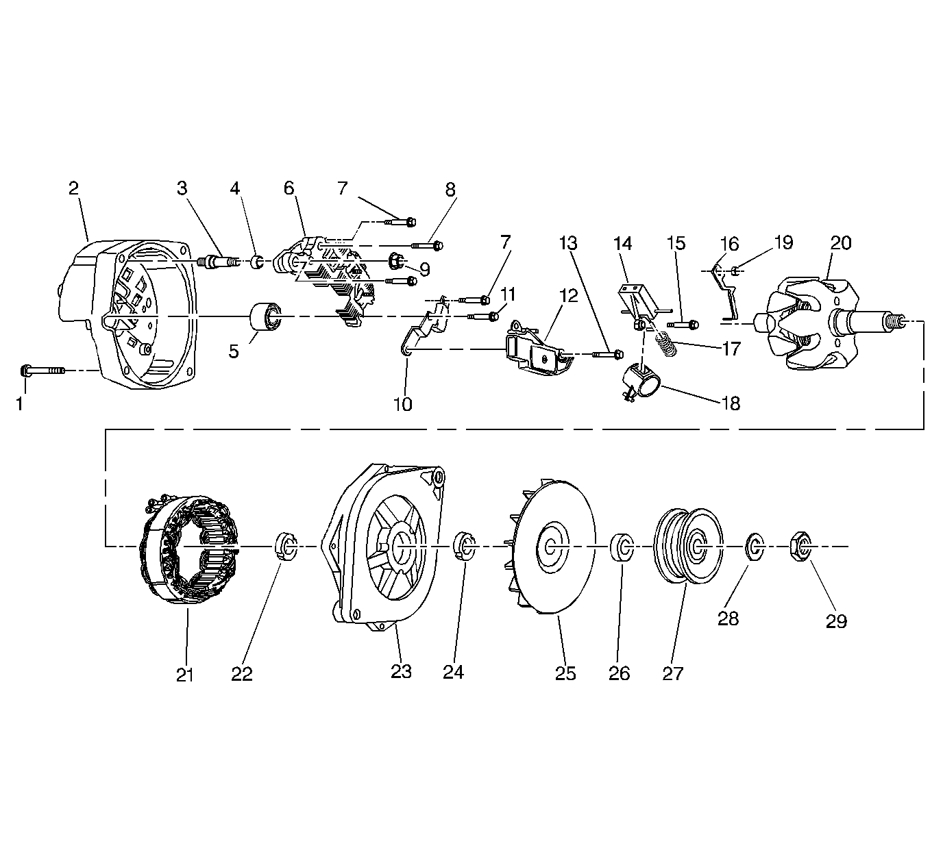

Object Number: 31764  Size: LF
(1)Generator Through Bolt
(2)Generator Slip Ring End Frame
(3)Generator Battery Terminal Stud
(4)Generator Battery Terminal Sleeve
(5)Generator Rotor Slip Ring End Frame Bearing
(6)Generator Rectifier Bridge
(7)Generator Rectifier Bridge Bolt
(8)Generator Capacitor/Rectifier Bolt
(9)Generator Battery Terminal Nut
(10)Generator Capacitor
(11)Generator Capacitor/Rectifier Bolt
(12)Generator Voltage Regulator
(13)Generator Voltage Regulator Attaching Bolt
(14)Generator Brush Holder
(15)Generator Brush Holder Bolt
(16)Generator Voltage Regulator Connector Strap
(17)Generator Brush Spring
(18)Dust Shield
(19)Generator Stator Lead Attaching Nut
(20)Generator Rotor
(21)Generator Stator
(22)Generator Rotor Drive End Bearing Inside Collar
(23)Generator Rotor Drive End Bearing Frame
(24)Generator Rotor Drive End Bearing Outside Collar
(25)Generator Fan
(26)Generator Rotor Drive End Fan Collar
(27)Generator Pulley
(28)Generator Rotor Shaft Drive End Washer
(29)Generator Rotor Shaft Drive End Nut

The VOLTS or CHECK GAGES indicator bulb receives ignition voltage. This voltage is then sent to the generator to power the field. If the generator detects an error within, it will ground the circuit which will illuminate the bulb. This bulb will also be illuminated if the engine is not running (generator shaft not turning). The generator will also ground this circuit if the system voltage is too low or too high.

The regulator limits system voltage by controlling rotor field current. The rotor current is switched on and off at a fixed frequency of about 400 cycles per second. This controls radio noise. By varying the overall on-off time, the correct average field current for the proper system voltage can be obtained. At high speeds, the on time may be 10% and the off time 90%. At low speeds, on time may be 90% with off time 10%. The regulator voltage also varies with the system temperature.

The generator does not require lubrication. The rotor shaft is mounted on ball bearings at the slip ring end. Each contains a permanent grease supply.