For 1990-2009 cars only
Disassembly Procedure
Notice: Do not attempt to disassemble a CS-130 generator. Damage to the generator could result. The CS-130 generator is replaced as a complete unit. Only the CS-144 generator can be overhauled.
Notice: Do not pry against the stator or the slip ring end frame during generator disassembly. Damage to the generator may result.
- Make scribe marks on the following components in order to ease in assembly:
- Remove the 4 through bolts.
- Separate the slip ring end frame and the drive end frame.
- Remove the end frame bearing from the rotor shaft.
- Remove the stator lead nuts.
- Remove the stator from the slip ring end frame.
- Unsolder the following connections to the voltage regulator:
- Remove the brush holder insulator screw.
- Remove the voltage regulator screw.
- Remove the following components from the slip ring end frame:
- Remove the following components from the brush holder:
- Clean the brushes with a dry soft cloth.
- Remove the rectifier bridge and the capacitor as a unit:
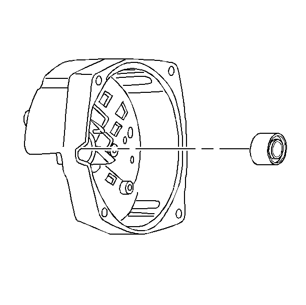
- Remove the slip ring end frame bearing.
- Remove the following from the drive end frame:
- Remove the rotor from the drive end frame.
- Remove the inside collar from the rotor.
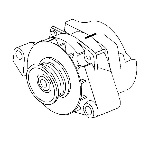
| • | The slip ring end frame |
| • | The drive end frame |
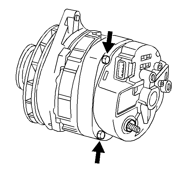
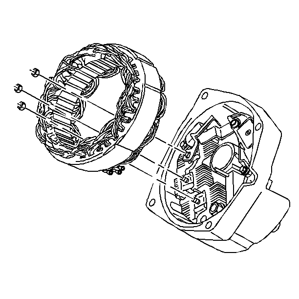
| • | The connector strap |
| • | The brush holder |
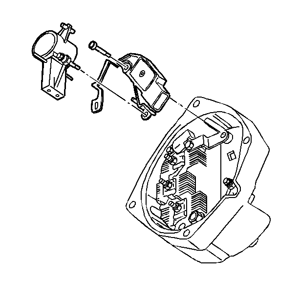
| • | The voltage regulator |
| • | The brush holder with the dust shield |
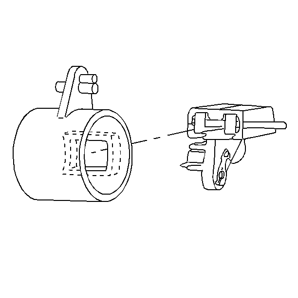
| • | The brushes |
| • | The dust shield |
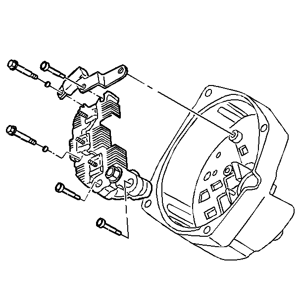
| • | Remove the bolts. |
| • | Remove the washers. |
| • | Disconnect the leads. |
| • | Remove the bridge and capacitor assembly. |
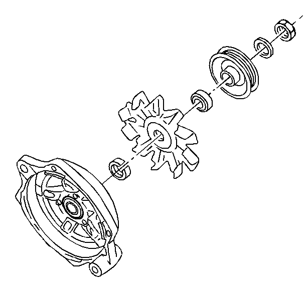
| • | The nut |
| • | The washer |
| • | The pulley |
| • | The fan collar |
| • | The fan |
| • | The outside collar |
| • | The rotor |
Inspection Procedure
- Refer to the Generator Component Test for Generator Diagnosis.
- Inspect the drive end bearing. If the bearing is rough or worn, replace the generator drive end frame assembly.
- Inspect the slip ring end bearing. If the bearing is rough or worn, replace with a new bearing.
- Inspect the rotor for grounds, opens, or shorts.
- The following test should be performed at approximately 21°C (70°F). A different temperature may result in inaccurate ohmmeter readings.
- Inspect the stator for grounds.
- Inspect the rectifier bridge for continuity.
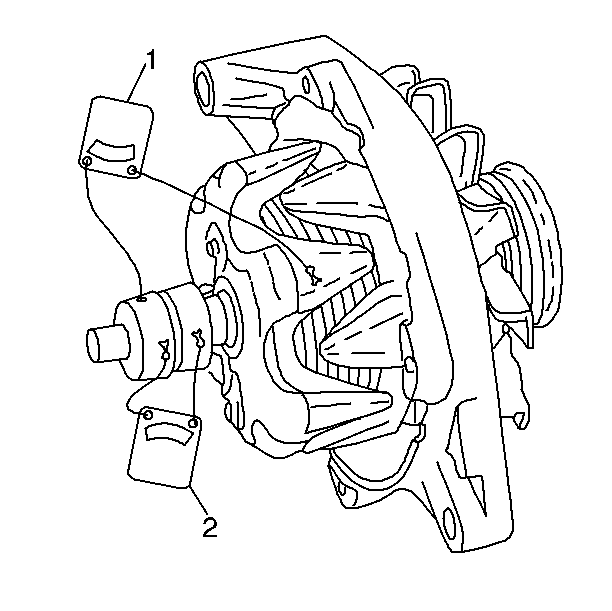
| 5.1. | Connect ohmmeter to slip ring and clean metal grounding surface on frame of rotor (1) to check for grounds. The ohmmeter should read infinity (open). If not, replace the rotor (1). |
| 5.2. | Connect ohmmeter to both slip rings to check for shorts and opens (2). The ohmmeter should read 1.7-2.1 ohms. If not, replace the rotor. |
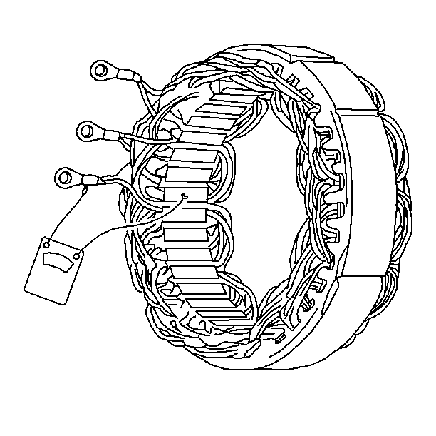
| 6.1. | Connect ohmmeter to stator terminal and to clean metal ground on laminations. |
| 6.2. | If ohmmeter reading is low, replace stator. Stator cannot be checked for opens and shorts with ohmmeter. |
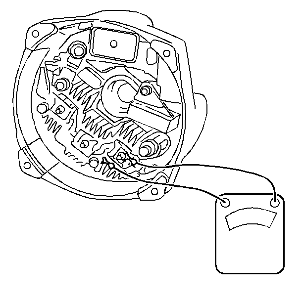
| 7.1. | Connect ohmmeter to grounded heat sink and flat metal clip at rectifier bridge. |
| 7.2. | Reverse leads. One reading should be high (open) and one low (continuity). If both readings are the same, replace the rectifier bridge. |
| 7.3. | Repeat test between grounded heat sink and clips at two other bridge terminals. |
| 7.4. | Repeat test between insulated heat sink and at bridge terminals. |
