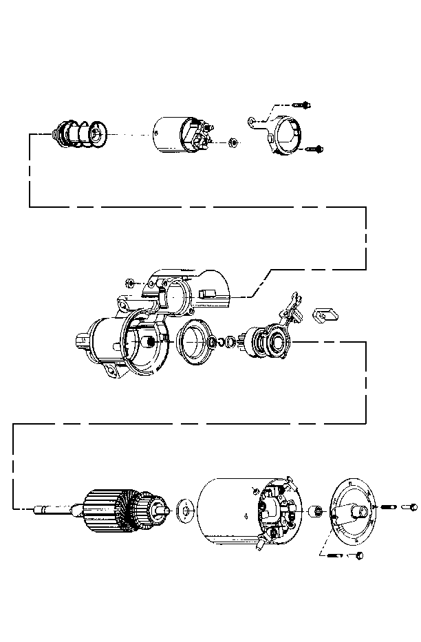
- Assemble the starter drive onto the armature shaft.
- Assemble the starter drive stop collar onto the armature shaft with flat side toward the starter drive.
- Assemble the new retainer onto the armature shaft and slide it down the shaft until seated in the shaft groove.
- Assemble the thrust collar onto the armature shaft with flange toward retainer.
- Assemble the shift lever to the starter drive by spreading the arms slightly.
- Assemble the plunger to the other end of the shift lever by snapping into place.
- Assemble the armature shaft into the end bearing while sliding the lever retainer into the slot drive housing.
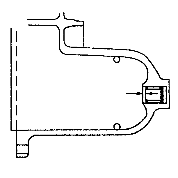
- Assemble the plug into the slot in the drive housing.
- Assemble the starter solenoid switch plunger spring over the plunger.
- Assemble the solenoid switch with the clamp to the drive housing.
- Assemble the clamp bolts/screws.
- Clean the contact surface of the frame kit brushes and armature commutator with a soft cloth.
- Assemble the frame kit onto the armature and drive housing by pushing in and holding brushes and aligning the notch in the frame kit with the locator on the drive housing. When in place, release the brushes and make sure they move freely and contact the commutator.
- Inspect the bearing in the commutator end frame. If the bearing has no visible lubrication or appears damaged, press in a new bearing until recessed 2 mm (0.08 in) into the commutator end frame. The bearing is pre-lubricated and no additional lubrication is needed.
- Assemble the washer onto the armature shaft.
- Assemble the commutator end frame onto the armature shaft and seat into the frame kit.
- Assemble the identification tag over the bolt/screw hole in the commutator end frame with the fluted end around the bearing well.
- Assemble the bolts/screws to the starter motor.
- Assemble the nut to the solenoid switch.
- Assemble the heat shield and nuts onto the protruding ends of the clamp bolts/screws.


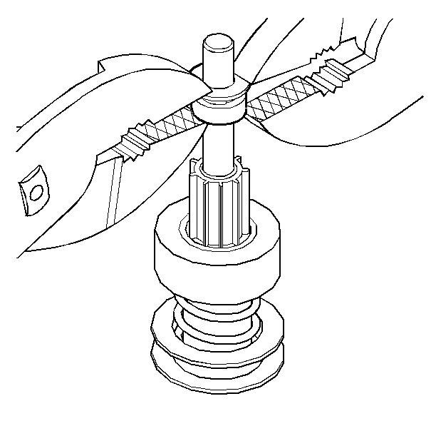
| • | Use two sets of pliers and squeeze the starter drive stop collar (58) and thrust collar to snap starter drive stop collar onto retainer. |
| • | Inspect the end bearing. If the bearing has no lubrication visible or appears damaged, replace the bearing. |
| • | Press the bearing from the drive housing and then press in the new bearing until recessed into drive housing casting. The bearing is pre-lubricated and no additional lubrication is needed. |

| • | Align the motor terminal and the solenoid switch with the field lead. |
Tighten
Tighten the clamp bolts/screws to 11 N·m (97 lb in).
Notice: Use the correct fastener in the correct location. Replacement fasteners must be the correct part number for that application. Fasteners requiring replacement or fasteners requiring the use of thread locking compound or sealant are identified in the service procedure. Do not use paints, lubricants, or corrosion inhibitors on fasteners or fastener joint surfaces unless specified. These coatings affect fastener torque and joint clamping force and may damage the fastener. Use the correct tightening sequence and specifications when installing fasteners in order to avoid damage to parts and systems.

Tighten
Tighten the bolts/screws to 8.5 N·m (75 ft in).
Notice: Before installing the starter motor to the engine, tighten the inner solenoid switch terminal nut on the cap to the solenoid BAT terminal. If this nut is not tight in the solenoid cap, the cap may be damaged during installation of electrical connections and cause the starter motor to fail later.
Tighten
Tighten the nut to 10 N·m (89 lb in).
Tighten
Tighten the nuts to 8 N·m (71 lb in).
