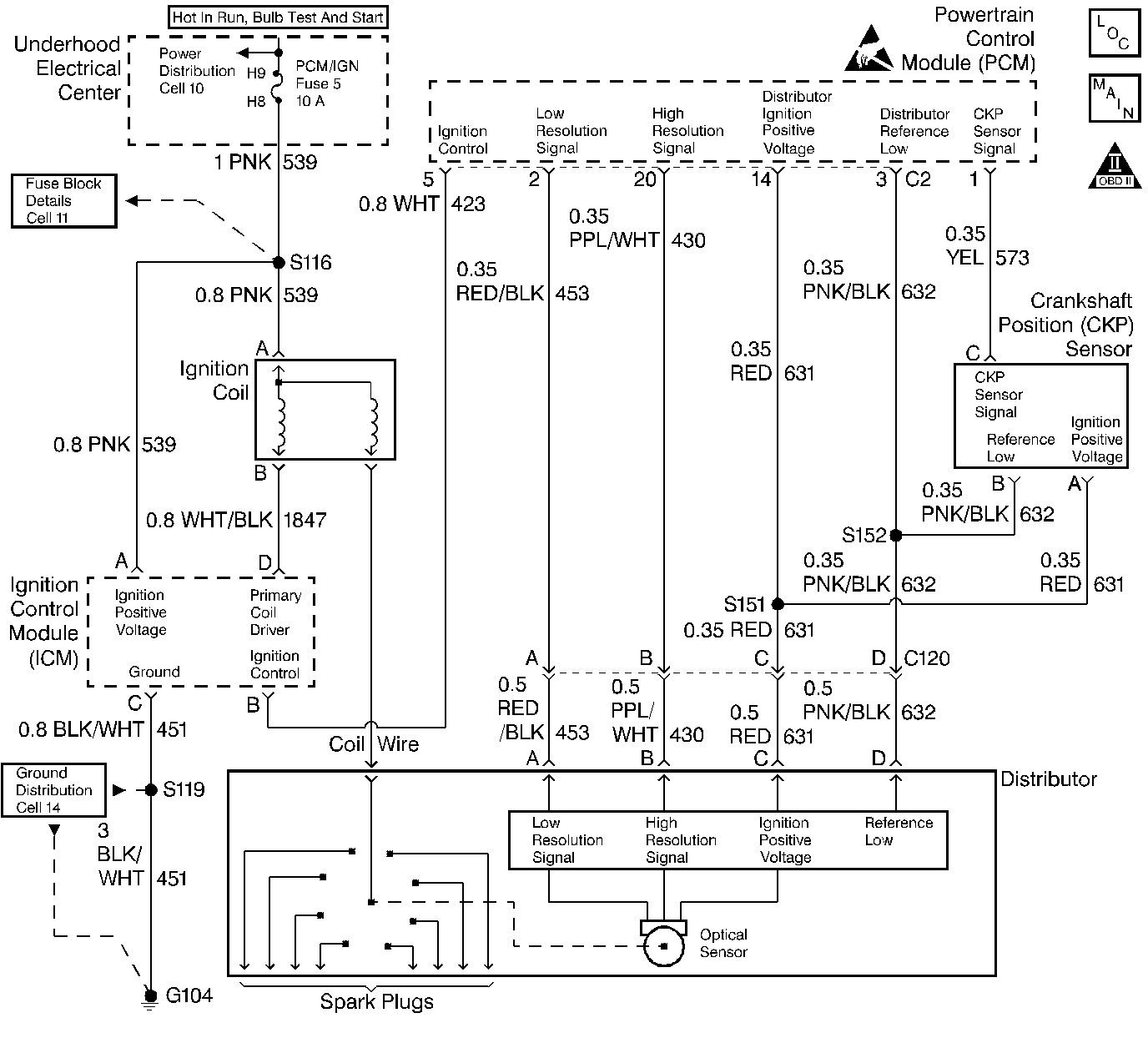
Circuit Description
The distributor ignition system supplies two timing inputs to the PCM, a high resolution signal (180 pulses per one crankshaft revolution) and a low resolution signal (4 pulses per one crankshaft revolution). The PCM can determine if one of the timing inputs is not being received by comparing the two inputs.
The high and low resolution circuits toggle between 0 and 5 volts as the camshaft turns. The following intermittent malfunctions to the low resolution circuit may cause a DTC P0323 to set:
| • | An open. |
| • | A short to voltage. |
| • | A short to ground. |
| • | A defective ignition module within the distributor. |
Conditions for Setting the DTC
| • | The PCM detects an interruption in the either the low or high resolution signal. |
Action Taken When the DTC Sets
| • | The DTC will be stored in the PCM memory when the diagnostic runs and fails. |
| • | The Malfunction Indicator Lamp (MIL) will not illuminate. |
| • | The PCM will record operating conditions at the time the diagnostic fails. This information will be stored in Failure Records. |
Conditions for Clearing the MIL/DTC
| • | A history DTC will clear after 40 consecutive warm-up cycles, if no failures are reported by this or any other non-emission related diagnostic. |
| • | A last test failed (Current DTC) will clear when the diagnostic runs and does not fail. |
| • | PCM battery voltage is interrupted. |
| • | Using a scan tool. |
Diagnostic Aids
| • | When DTC P0323 occurs, a misfire may be apparent. To locate an intermittent, use the scan tools snapshot feature. Try to duplicate the conditions under which the misfire is present. When reviewing captured data, watch for any abnormal high and low resolution timing pulses. |
| • | For intermittents, refer to Symptoms . |
Test Description
Number(s) below refer to step numbers on the diagnostic table.
-
Using Freeze Frame and/or Failure Records data may aid in locating an intermittent condition. If the DTC cannot be duplicated, the information included in the Freeze Frame and/or Failure Records data can be useful in determining how many miles since the DTC set. The Fail Counter and Pass Counter can also be used to determine how many ignition cycles the diagnostic reported a pass and/or a fail. Operate vehicle within the same freeze frame conditions (RPM, load, vehicle speed, temperature etc.) that were noted.
-
A defective ignition module within the distributor could cause this DTC to set. Inspect the distributor for signs of damage including contamination. Refer to Section 6D4, Ignition System. If distributor components must be replaced, check distributor vent system operation. Refer to Distributor Vent System Check .
Step | Action | Value(s) | Yes | No |
|---|---|---|---|---|
1 | Was the Powertrain On-Board Diagnostic (OBD) System Check performed? | -- | ||
2 |
Did DTC P0372 or P1371 fail this ignition cycle? | -- | Go to applicable DTC Table | |
3 |
Does the Engine Speed display change abruptly, or does an engine miss or stall occur while a related connector is being moved? | -- | ||
4 | Using a scan tool, observe Engine Speed while moving related wiring harnesses. Also watch for an engine miss or stall when the harness is moved. Does the Engine Speed display change abruptly, or does an engine miss or stall occur while moving related electrical harnesses? | -- | ||
5 |
Does the scan tool indicate that this diagnostic failed this ignition? | -- | Go to Diagnostic Aids | |
6 | Repair the damage connectors/terminals. Refer to Repair Procedures in Electrical Diagnosis (8A Cell 5). Is the action complete? | -- | -- | |
7 | Repair faulty wiring. Refer to Repair Procedures in Electrical Diagnosis (8A Cell 5). Is the action complete? | -- | -- | |
8 |
Is the action complete? | -- | -- | |
9 |
Does the scan tool indicate that this test ran and passed? | -- | ||
10 | Using the scan tool, select Capture Info, Review Info. Are any DTCs displayed that have not been diagnosed? | -- | Go to the applicable DTC table | System OK |
