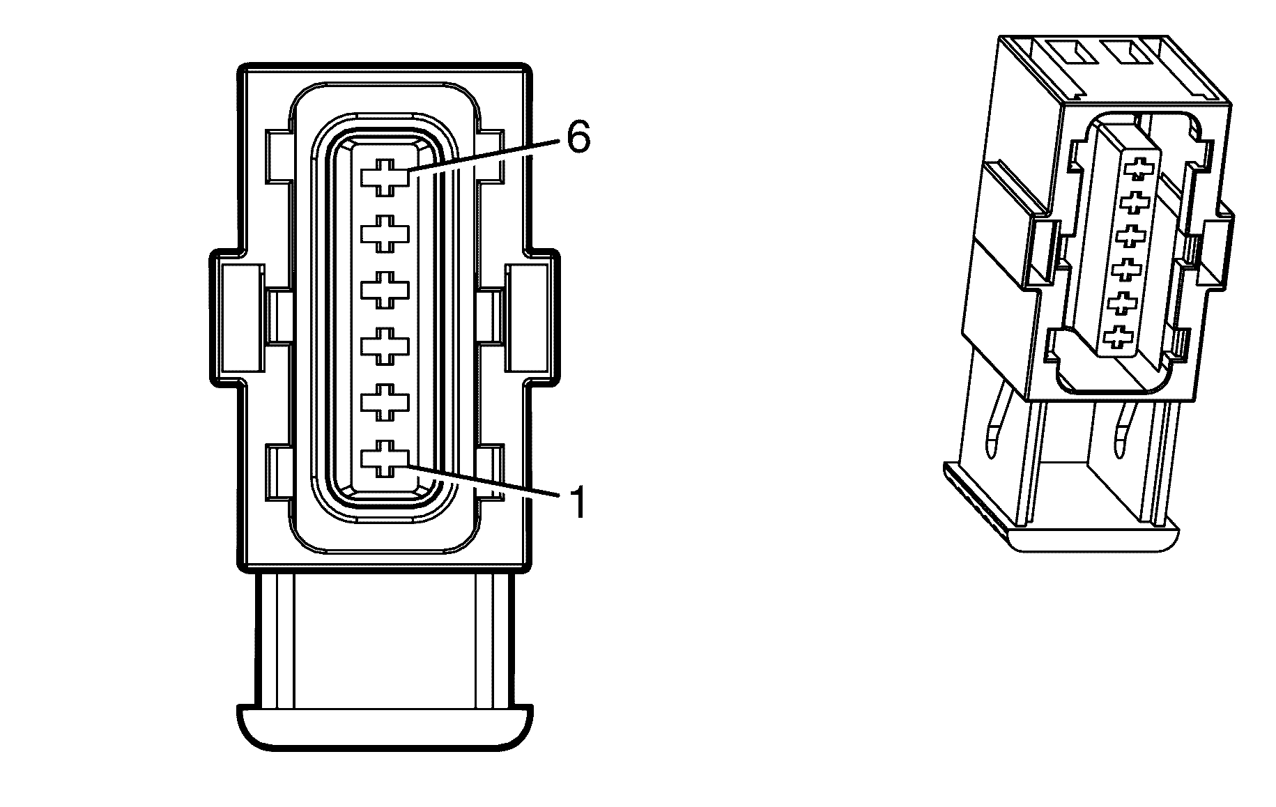
| |||
|---|---|---|---|
Connector Part Information | |||
Pin | Wire Colour | Wire Size | Function |
1 | BN/YE | 0.5 | 5-Volt Reference |
2 | WH/BK | 0.5 | 5-Volt Reference |
3 | BU/WH | 0.5 | APP Sensor 1 Signal |
4 | BN | 0.5 | Low Reference |
5 | PU | 0.5 | Low Reference |
6 | L-BU | 0.5 | APP Sensor 2 Signal |
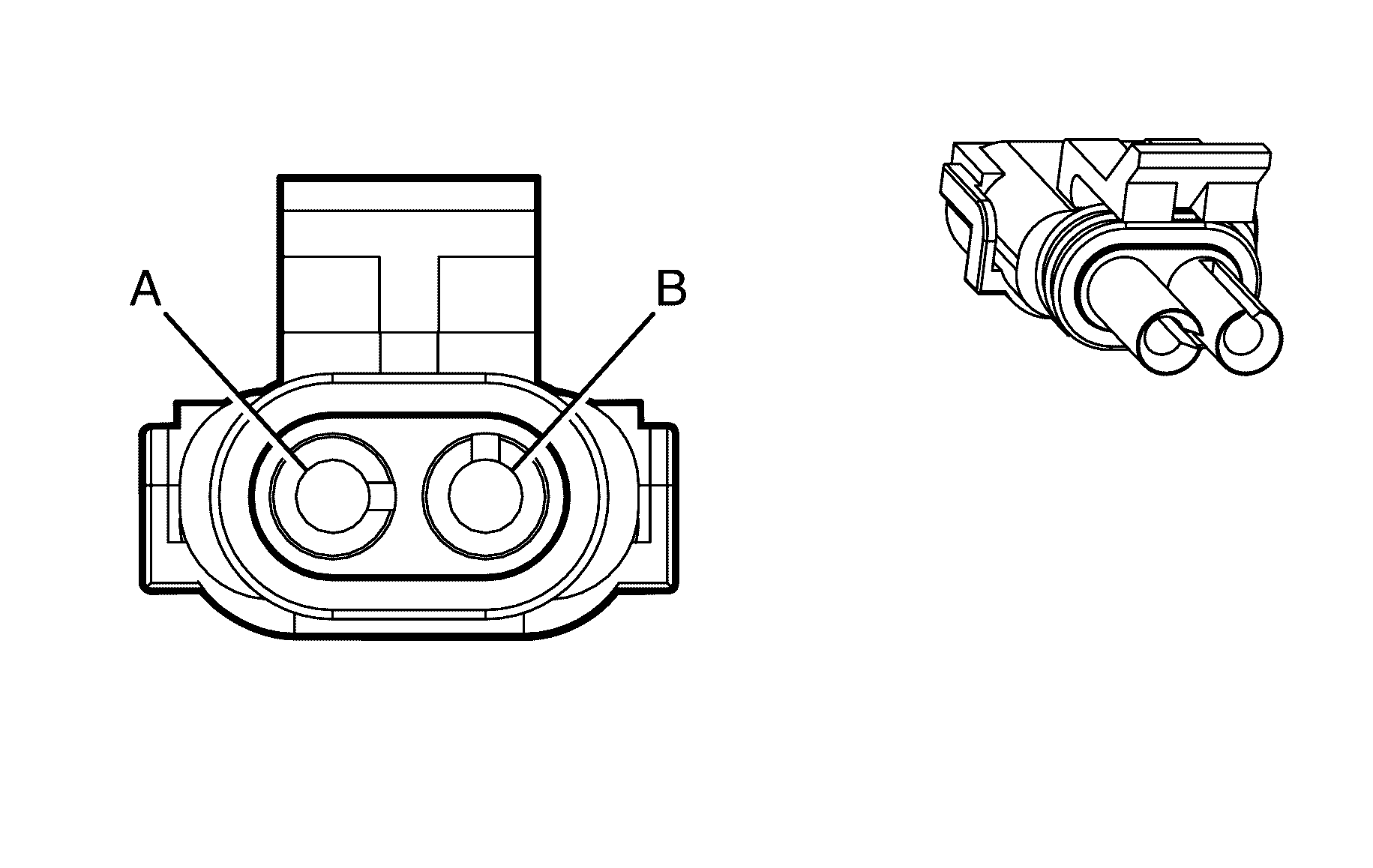
| |||
|---|---|---|---|
Connector Part Information | |||
Pin | Wire Colour | Wire Size | Function |
1 | L-GN | 0.5 | Backup Lamp Switch Signal |
2 | BK | 0.5 | Ground |
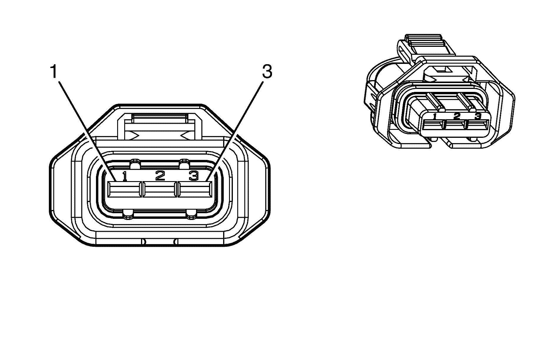
| |||
|---|---|---|---|
Connector Part Information | |||
Pin | Wire Colour | Wire Size | Function |
1 | PK/BK | 0.75 | Low Reference |
2 | D-GN | 0.5 | CMP Sensor Signal - Exhaust Bank 1 |
3 | GY | 0.75 | 5-Volt Reference |

| |||
|---|---|---|---|
Connector Part Information | |||
Pin | Wire Colour | Wire Size | Function |
1 | PK/BK | 0.5 | Low Reference |
2 | PU | 0.5 | CMP Sensor Signal - Exhaust Bank 2 |
3 | GY | 0.5 | 5-Volt Reference |
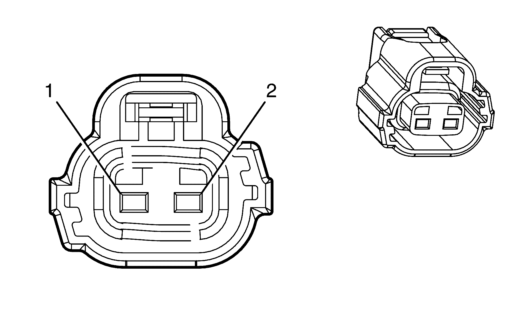
| |||
|---|---|---|---|
Connector Part Information | |||
Pin | Wire Colour | Wire Size | Function |
1 | PK/BU | 0.75 | Ignition 1 Voltage |
2 | L-GN | 0.75 | CMP Actuator Solenoid Control - Exhaust Bank 1 |

| |||
|---|---|---|---|
Connector Part Information | |||
Pin | Wire Colour | Wire Size | Function |
1 | PK/BU | 0.75 | Ignition 1 Voltage |
2 | WH/BK | 0.75 | CMP Actuator Solenoid Control - Exhaust Bank 2 |

| |||
|---|---|---|---|
Connector Part Information | |||
Pin | Wire Colour | Wire Size | Function |
1 | PK/BK | 0.5 | Low Reference |
2 | OG/BU | 0.5 | CMP Sensor Signal - Intake Bank 1 |
3 | GY | 0.5 | 5-Volt Reference |

| |||
|---|---|---|---|
Connector Part Information | |||
Pin | Wire Colour | Wire Size | Function |
1 | PK/BK | 0.5 | Low Reference |
2 | PU | 0.5 | CMP Sensor Signal - Intake Bank 2 |
3 | GY | 0.5 | 5-Volt Reference |

| |||
|---|---|---|---|
Connector Part Information | |||
Pin | Wire Colour | Wire Size | Function |
1 | PK/BU | 0.75 | Ignition 1 Voltage |
2 | PU | 0.75 | CMP Actuator Solenoid Control - Intake Bank 1 |

| |||
|---|---|---|---|
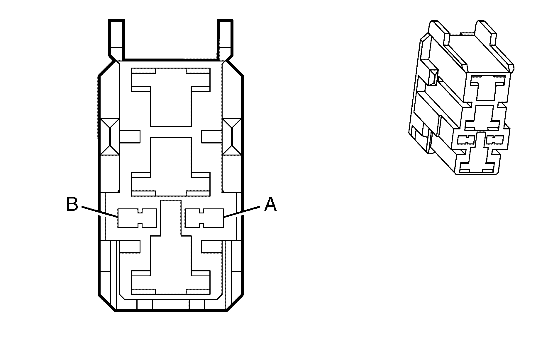
Connector Part Information | |||
Pin | Wire Colour | Wire Size | Function |
1 | PK/BU | 0.75 | Ignition 1 Voltage |
2 | OG/BK | 0.75 | CMP Actuator Solenoid Control - Intake Bank 2 |
| |||
|---|---|---|---|
Connector Part Information | |||
Pin | Wire Colour | Wire Size | Function |
A | BN/WH | 0.5 | Cruise Cancel Signal |
B | PK/BU | 0.5 | Ignition 1 Voltage |

| |||
|---|---|---|---|
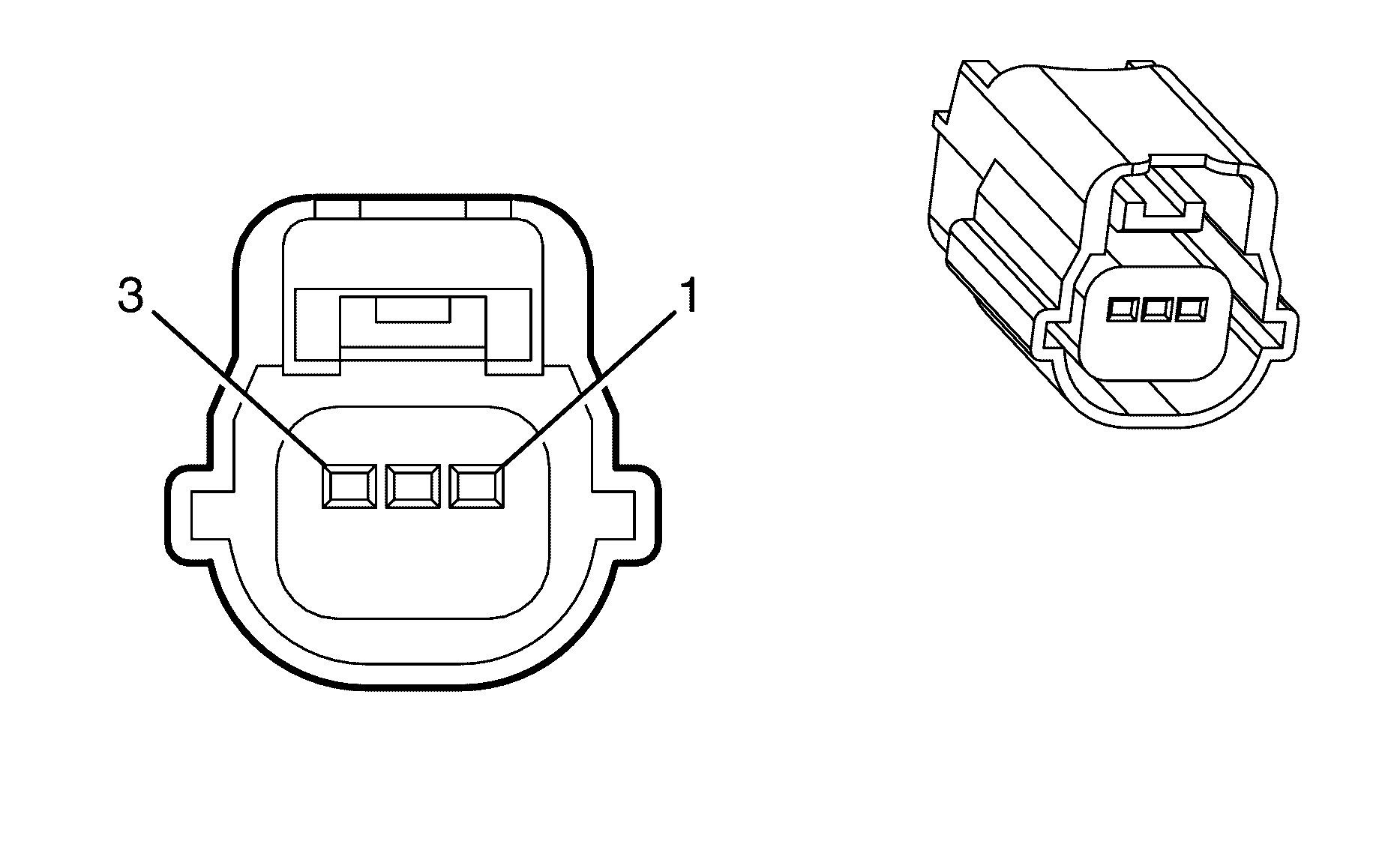
Connector Part Information | |||
Pin | Wire Colour | Wire Size | Function |
A | OG/BK | 0.5 | Park/Neutral Signal |
B | BK | 0.5 | Ground |
| |||
|---|---|---|---|
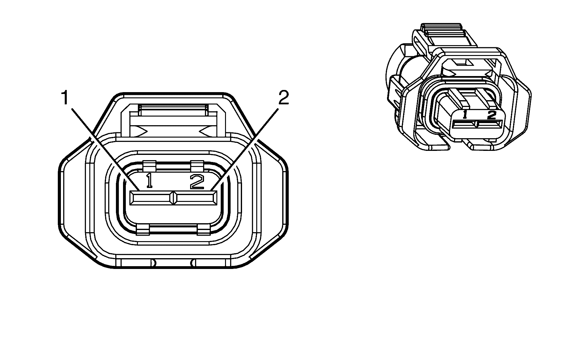
Connector Part Information | |||
Pin | Wire Colour | Wire Size | Function |
1 | PU | 0.5 | Low Reference |
2 | YE/BU | 0.5 | CKP Sensor Signal |
3 | PU/WH | 0.5 | 5-Volt Reference |
| |||
|---|---|---|---|
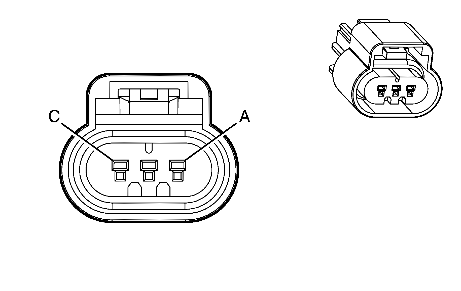
Connector Part Information | |||
Pin | Wire Colour | Wire Size | Function |
1 | YE/GN | 0.5 | ECT Sensor Signal |
2 | BK | 0.5 | Low Reference |
| |||
|---|---|---|---|
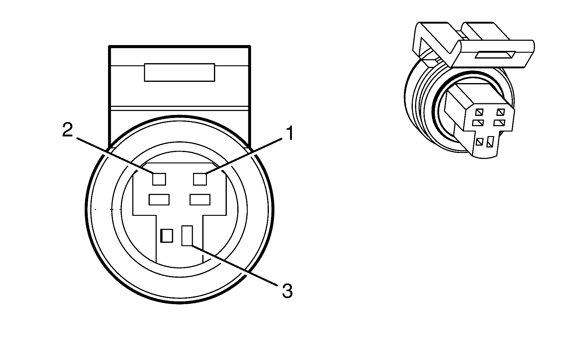
Connector Part Information | GT 150 Sealed 4.5 | ||
Pin | Wire Colour | Wire Size | Function |
A | BN | 0.5 | Oil Level Switch Signal |
B | GN/YE | 0.5 | Oil Temperature Sensor Signal |
C | BK | 0.5 | Low Reference |
| |||
|---|---|---|---|
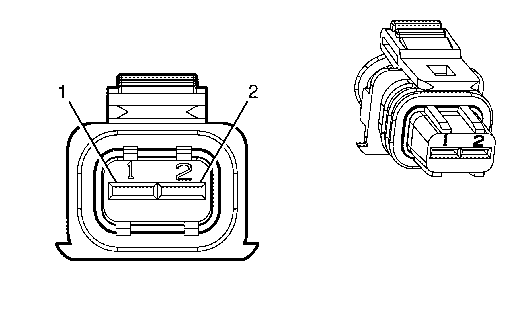
Connector Part Information | GT 150 Series, Sealed | ||
Pin | Wire Colour | Wire Size | Function |
1 | BN/RD | 0.5 | Low Reference |
2 | GY | 0.5 | 5-Volt Reference |
3 | BN/WH | 0.5 | Oil Pressure Sensor Signal |
| |||
|---|---|---|---|
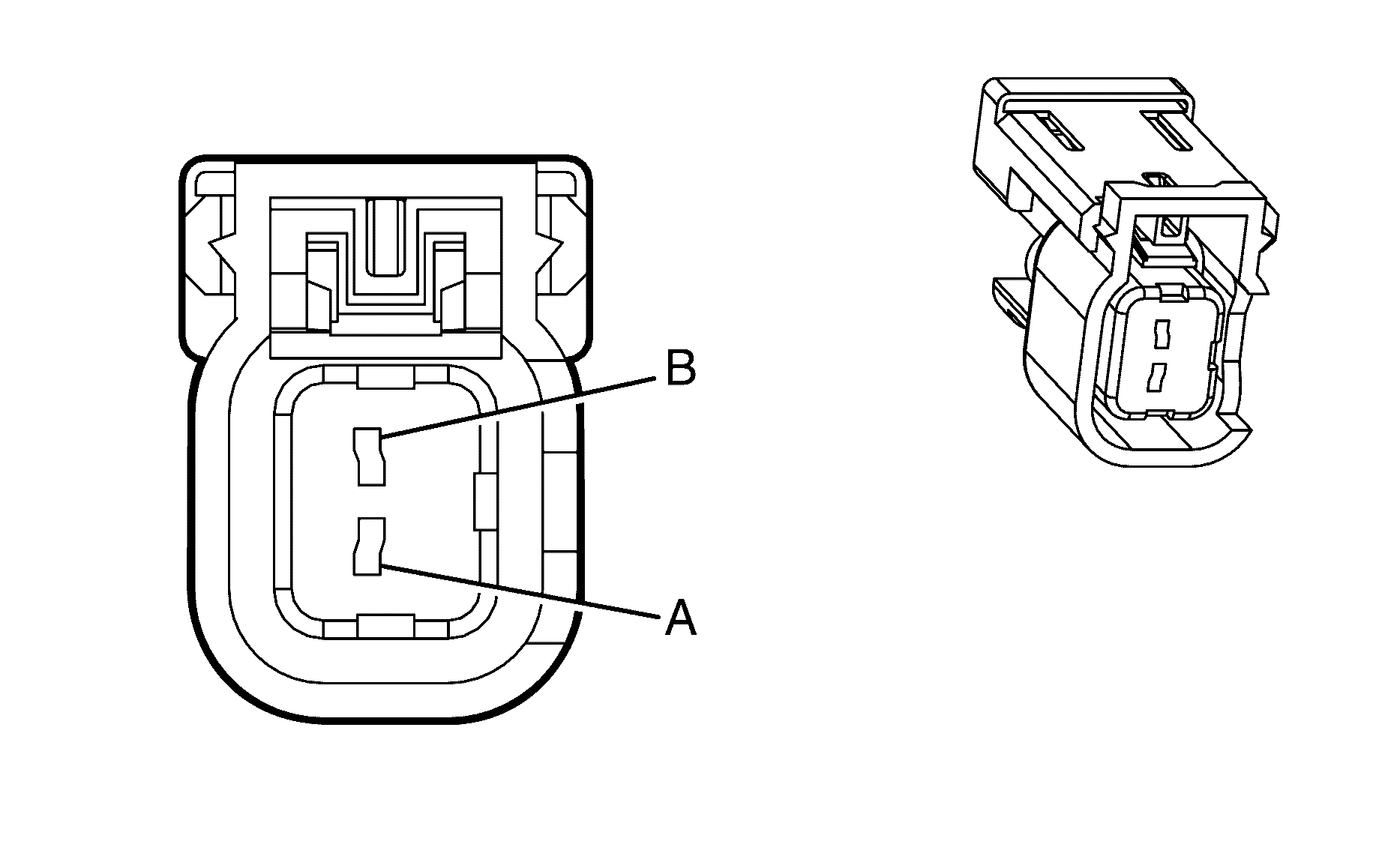
Connector Part Information | |||
Pin | Wire Colour | Wire Size | Function |
1 | PK/BU | 0.75 | Ignition 1 Voltage |
2 | D-GN/WH | 0.75 | EVAP Canister Purge Solenoid Control |
| |||
|---|---|---|---|
Connector Part Information | |||
Pin | Wire Colour | Wire Size | Function |
A | PK/BU | 0.8 | Ignition 1 Voltage |
B | BN/BK | 0.8 | Fuel Injector 1 Control |

| |||
|---|---|---|---|
Connector Part Information | |||
Pin | Wire Colour | Wire Size | Function |
A | PK | 0.8 | Ignition 1 Voltage |
B | L-GN/BK | 0.8 | Fuel Injector 2 Control |

| |||
|---|---|---|---|
Connector Part Information | |||
Pin | Wire Colour | Wire Size | Function |
A | PK/BU | 0.8 | Ignition 1 Voltage |
B | PK/BK | 0.8 | Fuel Injector 3 Control |

| |||
|---|---|---|---|
Connector Part Information | |||
Pin | Wire Colour | Wire Size | Function |
A | PK | 0.8 | Ignition 1 Voltage |
B | L-BU/BK | 0.8 | Fuel Injector 4 Control |

| |||
|---|---|---|---|
Connector Part Information | |||
Pin | Wire Colour | Wire Size | Function |
A | PK/BU | 0.8 | Ignition 1 Voltage |
B | BN/WH | 0.8 | Fuel Injector 5 Control |

| |||
|---|---|---|---|
Connector Part Information | |||
Pin | Wire Colour | Wire Size | Function |
A | PK | 0.8 | Ignition 1 Voltage |
B | YE/BK | 0.8 | Fuel Injector 6 Control |
| |||
|---|---|---|---|
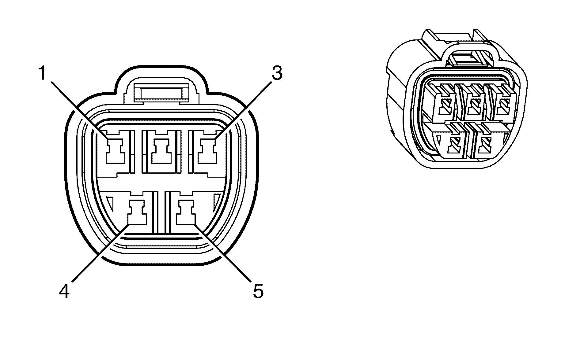
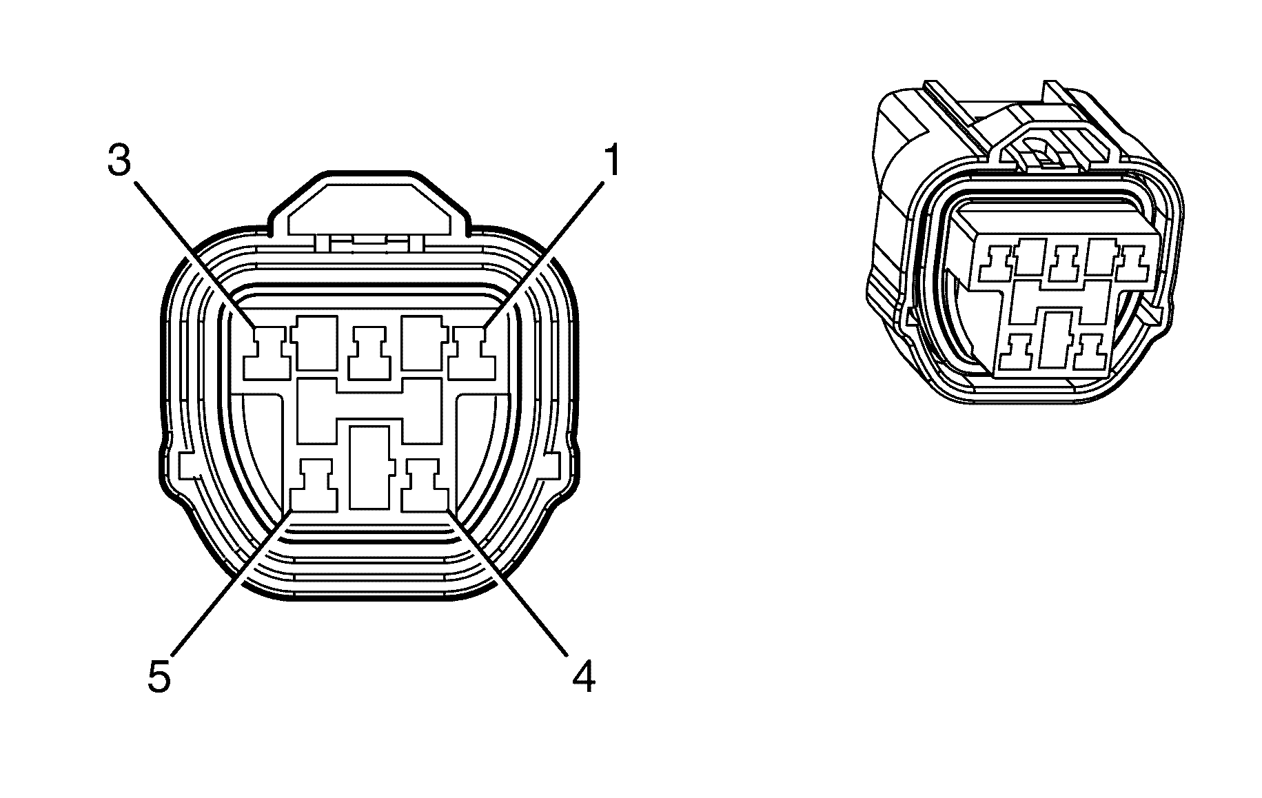
Connector Part Information | |||
Pin | Wire Colour | Wire Size | Function |
1 | BN/YE | 0.3 | Fuel Return |
2 | L-BU | 0.5 | Fuel Level |
3 | -- | -- | Not Used |
4 | -- | -- | Not Used |
5 | -- | -- | Not Used |
| |||
|---|---|---|---|
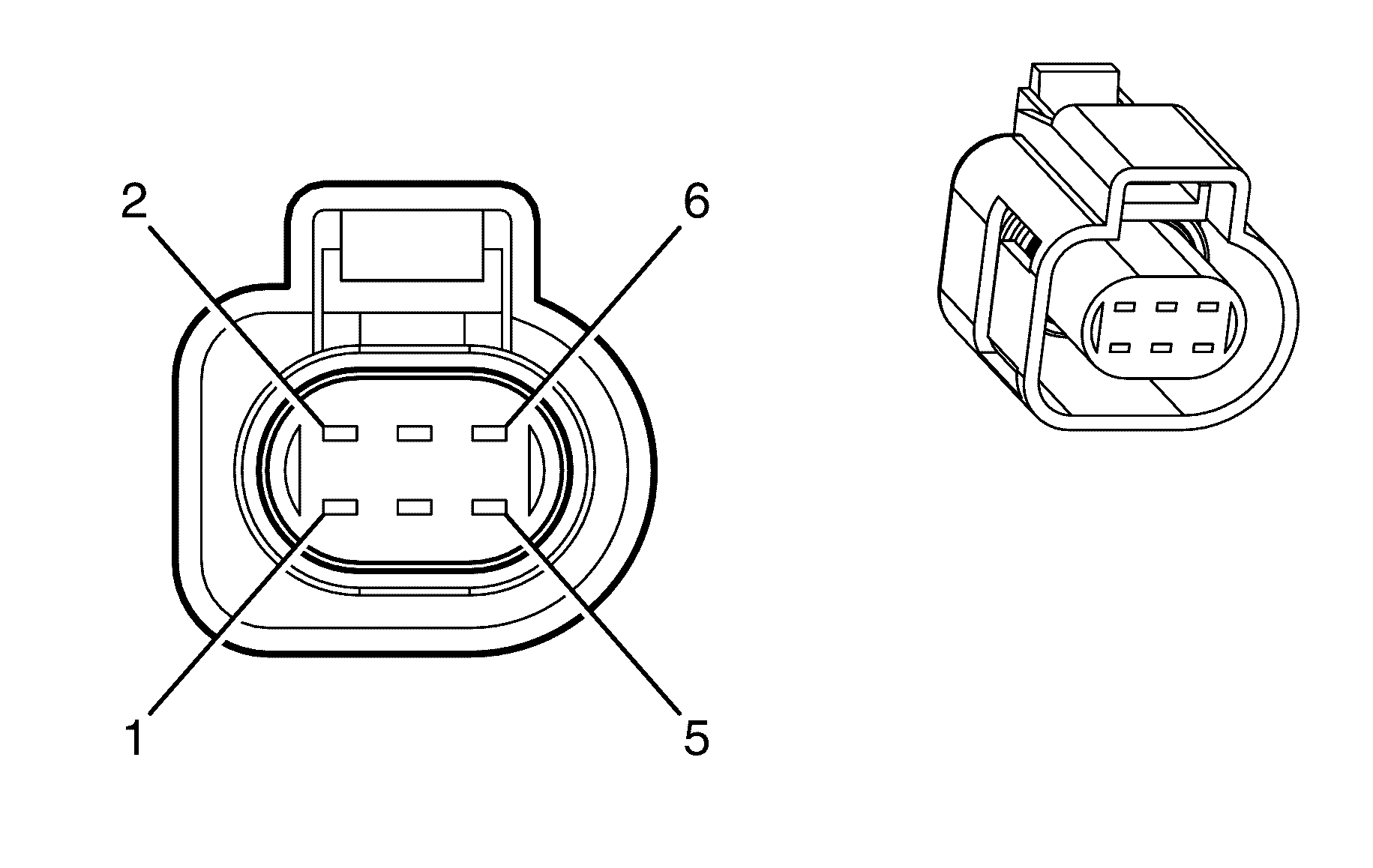
Connector Part Information | |||
Pin | Wire Colour | Wire Size | Function |
1 | GY | 2.0 | Fuel Pump Supply Voltage |
2 | PU | 0.5 | Fuel Level Sensor Signal (Primary) |
3 | BK | 2.0 | Ground |
4 | BN/YE | 0.5 | Low Reference |
5 | -- | -- | Not Used |
| |||
|---|---|---|---|
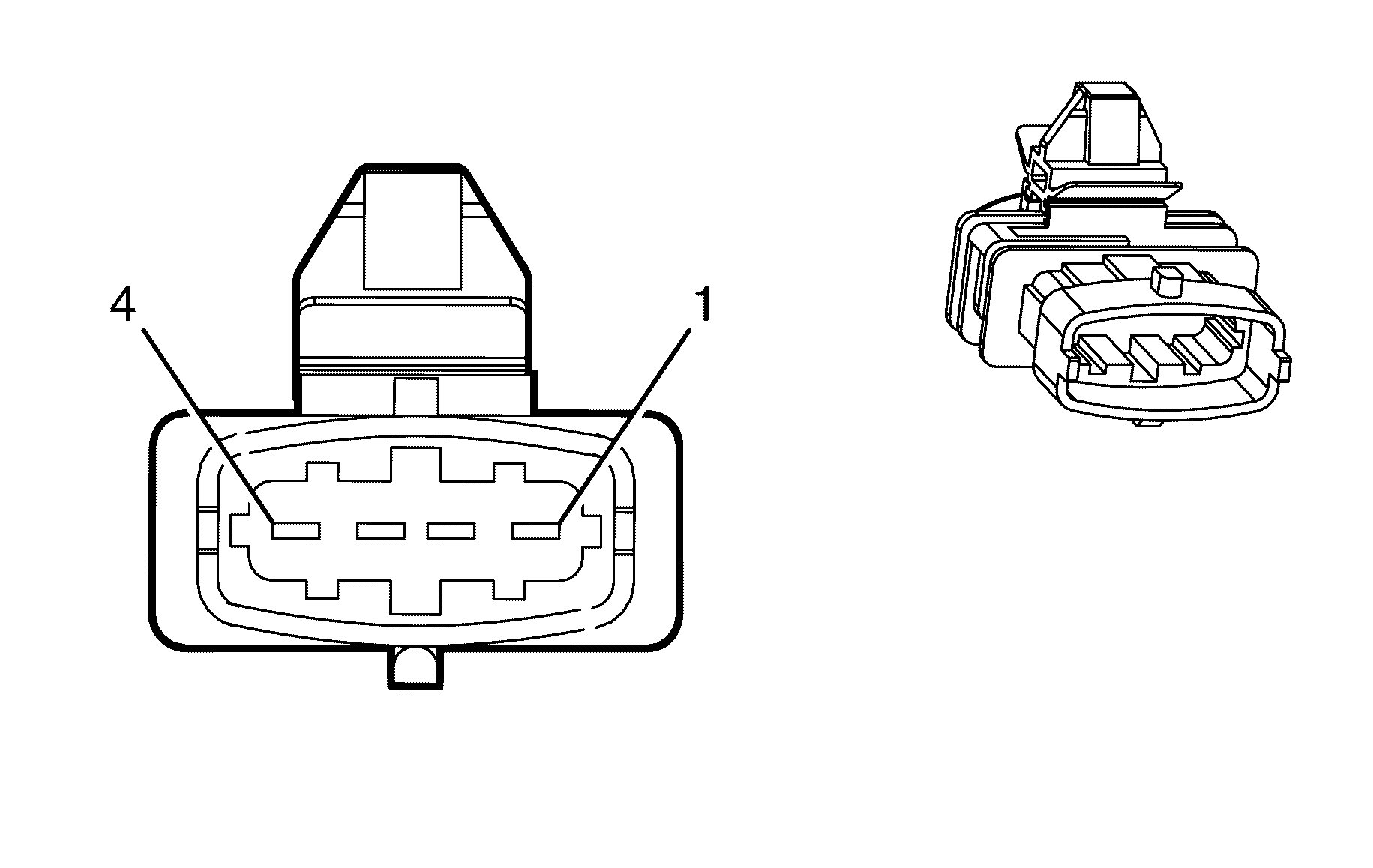
Connector Part Information | |||
Pin | Wire Colour | Wire Size | Function |
1 | WH | 0.5 | HO2S Output Pump Current (Bank 1 Sensor 1) |
2 | BN/YE | 0.5 | HO2S Low Signal (Bank 1 Sensor 1) |
3 | GY/WH | 0.75 | HO2S Heater Low Control (Bank 1 Sensor 1) |
4 | PK/BUK | 0.75 | Ignition 1 Voltage |
5 | L-GN | 0.5 | HO2S Input Pump Current (Bank 1 Sensor 1) |
6 | PU/WH | 0.5 | HO2S High Signal (Bank 1 Sensor 1) |
| |||
|---|---|---|---|
Connector Part Information | |||
Pin | Wire Colour | Wire Size | Function |
1 | PK/D-BU | 0.75 | Ignition 1 Voltage |
2 | OG/WH | 0.75 | HO2S Heater Low Control (Bank 1 Sensor 2) |
3 | BN/RD | 0.5 | HO2S Low Signal (Bank 1 Sensor 2) |
4 | PU | 0.5 | HO2S High Signal (Bank 1 Sensor 2) |

| |||
|---|---|---|---|
Connector Part Information | |||
Pin | Wire Colour | Wire Size | Function |
1 | PU/WH | 0.5 | HO2S Pump Output Current (Bank 2 Sensor 1) |
2 | BN/RD | 0.5 | HO2S Low Signal (Bank 2 Sensor 1) |
3 | L-GN | 0.75 | HO2S Heater Low Control (Bank 2 Sensor 1) |
4 | PK/BU | 0.75 | Battery 1 Voltage |
5 | OG | 0.5 | HO2S Input Pump Current (Bank 2 Sensor 1) |
6 | PU | 0.5 | HO2S High Signal (Bank 2 Sensor 1) |

| |||
|---|---|---|---|
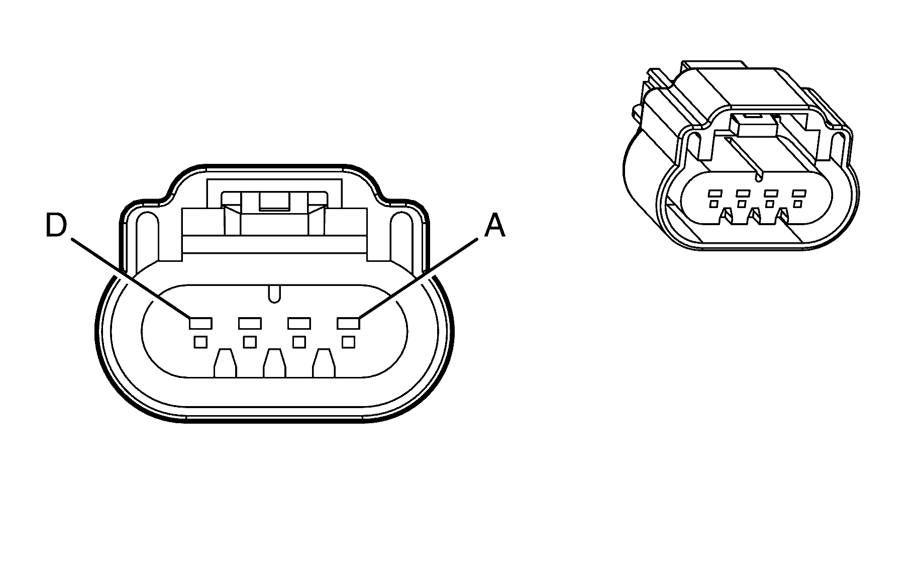
Connector Part Information | |||
Pin | Wire Colour | Wire Size | Function |
1 | PK/D-BU | 0.75 | Battery 1 Voltage |
2 | GY/WH | 0.75 | HO2S Heater Low Control (Bank 2 Sensor 2) |
3 | BN/GN | 0.5 | HO2S Low Signal (Bank 2 Sensor 2) |
4 | PU | 0.5 | HO2S High Signal (Bank 2 Sensor 2) |
| |||
|---|---|---|---|
Connector Part Information | Global Terminal/150 | ||
Pin | Wire Colour | Wire Size | Function |
A | BK | 0.75 | Ground |
B | PU | 0.5 | Low Reference |
C | PU | 0.5 | IC 1 Control |
D | PK/BU | 0.75 | Ignition 1 Voltage |

| |||
|---|---|---|---|
Connector Part Information | Global Terminal/150 | ||
Pin | Wire Colour | Wire Size | Function |
A | BK | 0.75 | Ground |
B | PK | 0.5 | Low Reference |
C | OG/WH | 0.5 | IC 2 Control |
D | PK | 0.75 | Ignition 1 Voltage |

| |||
|---|---|---|---|
Connector Part Information | Global Terminal/150 | ||
Pin | Wire Colour | Wire Size | Function |
A | BK | 0.75 | Ground |
B | PU | 0.5 | Low Reference |
C | L-BU | 0.5 | IC 3 Control |
D | PK/BU | 0.75 | Ignition 1 Voltage |

| |||
|---|---|---|---|
Connector Part Information | Global Terminal/150 | ||
Pin | Wire Colour | Wire Size | Function |
A | BK | 0.75 | Ground |
B | PK | 0.5 | Low Reference |
C | D-GN/WH | 0.5 | IC 4 Control |
D | PK | 0.75 | Ignition 1 Voltage |

| |||
|---|---|---|---|
Connector Part Information | Global Terminal/150 | ||
Pin | Wire Colour | Wire Size | Function |
A | BK | 0.75 | Ground |
B | PU | 0.5 | Low Reference |
C | GN/RD | 0.5 | IC 5 Control |
D | PK/BU | 0.75 | Ignition 1 Voltage |

| |||
|---|---|---|---|
Connector Part Information | Global Terminal/150 | ||
Pin | Wire Colour | Wire Size | Function |
A | BK | 0.75 | Ground |
B | PK | 0.5 | Low Reference |
C | L-BU/WH | 0.5 | IC 6 Control |
D | PK | 0.75 | Ignition 1 Voltage |

| |||
|---|---|---|---|
Connector Part Information | |||
Pin | Wire Colour | Wire Size | Function |
1 | D-BU | 0.5 | Knock Sensor 1 Signal |
2 | GY | 0.5 | Low Reference Knock Sensor Signal Return |

| |||
|---|---|---|---|
Connector Part Information | |||
Pin | Wire Colour | Wire Size | Function |
1 | L-BU | 0.5 | Knock Sensor 2 Signal |
2 | BN | 0.5 | Low Reference Knock Sensor Signal Return |
| |||
|---|---|---|---|
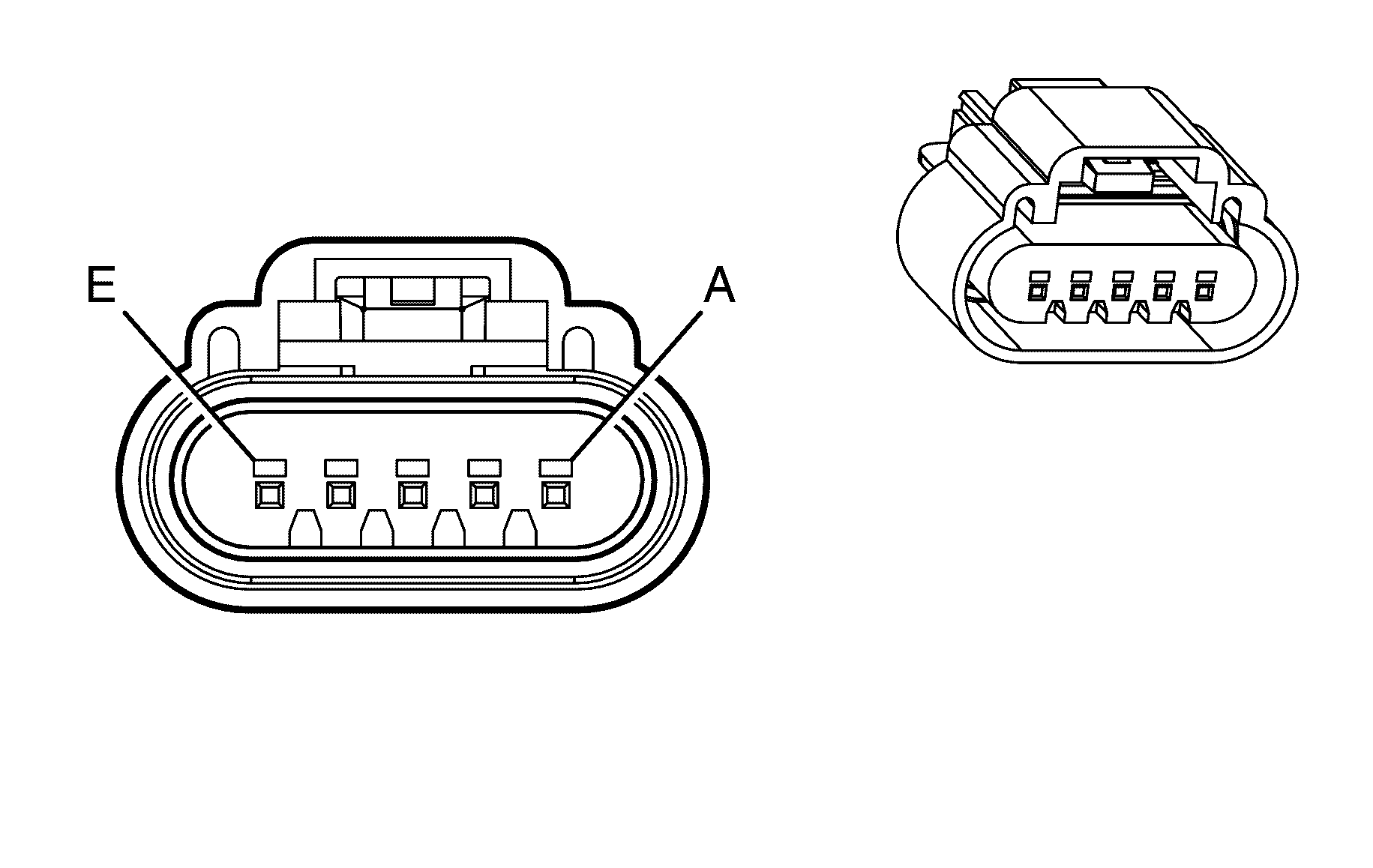
Connector Part Information | GT 150 Sealed 4.0 | ||
Pin | Wire Colour | Wire Size | Function |
A | YE | 0.5 | MAF Sensor Signal |
B | PK | 0.5 | Ignition 1 Voltage |
C | BK | 0.5 | Ground |
D | BN/RD | 0.5 | IAT Sensor Signal |
E | BN/WH | 0.5 | Low Reference |
| |||
|---|---|---|---|
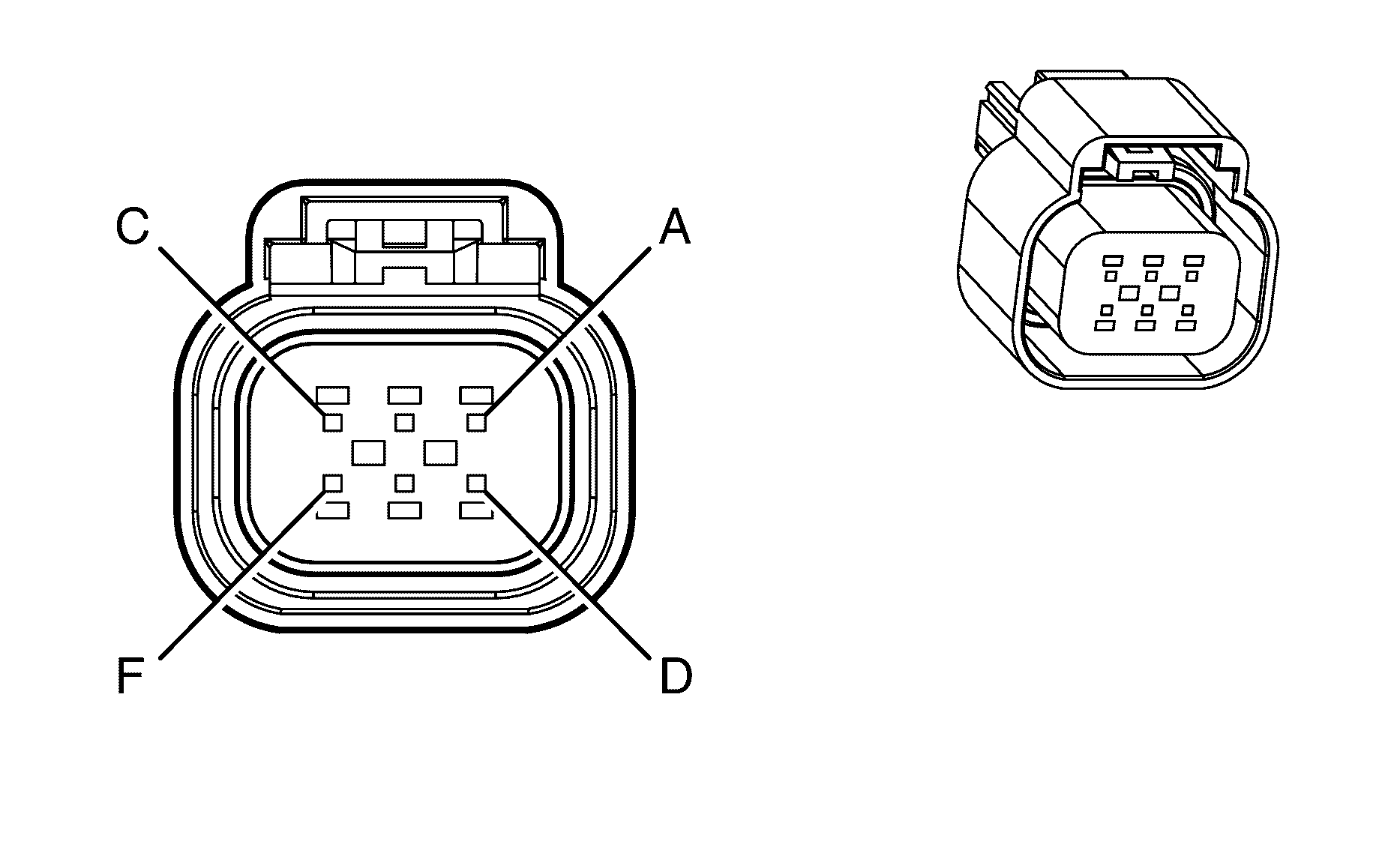
Connector Part Information | GT 150 Series, Sealed | ||
Pin | Wire Colour | Wire Size | Function |
A | BN | 0.75 | TAC Motor Control - 2 |
B | YE | 0.75 | TAC Motor Control - 1 |
C | BN/BK | 0.5 | Low Reference |
D | D-GN | 0.5 | TP Sensor 1 Signal |
E | GY | 0.5 | 5-Volt Reference |
F | PU | 0.5 | TP Sensor 2 Signal |

| |||
|---|---|---|---|
Connector Part Information | GT 150 Sealed 4.0 | ||
Pin | Wire Colour | Wire Size | Function |
A | PK/BU | 0.75 | Ignition 1 Voltage |
B | BN | 0.75 | PWM_OUT |
C | PU/BK | 0.75 | PWR_RTN |
D | L-BU/WH | 0.75 | PWM |
E | BK | 0.75 | Ground |
| |||
|---|---|---|---|
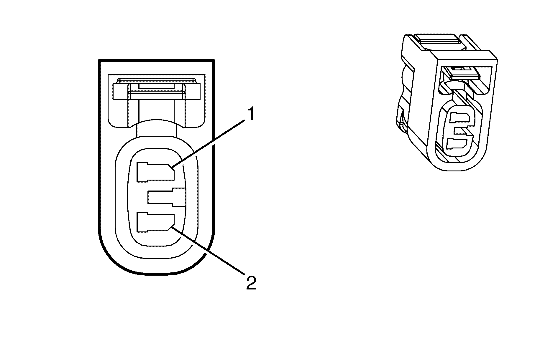
Connector Part Information | .090 Class II Sealed Series | ||
Pin | Wire Colour | Wire Size | Function |
1 | PU/BK | 0.75 | PWM_RTN |
2 | BN | 0.75 | PWR_OUT |
