For 1990-2009 cars only
Body Control Module Replacement for Chevrolet Caprice WM 2008
Body Control Module Replacement RHD
Removal Procedure
- Disconnect the negative battery cable. Refer to Battery Negative Cable Disconnection and Connection .
- Disable the SIR system. Refer to SIR Disabling and Enabling .
- Remove the right closeout insulator panel. Refer to Instrument Panel Insulator Panel Replacement - Right Side .
- Remove the knee bolster. Refer to Knee Bolster Replacement .
- Remove the instrument panel retainer. Refer to Instrument Panel Retainer Replacement .
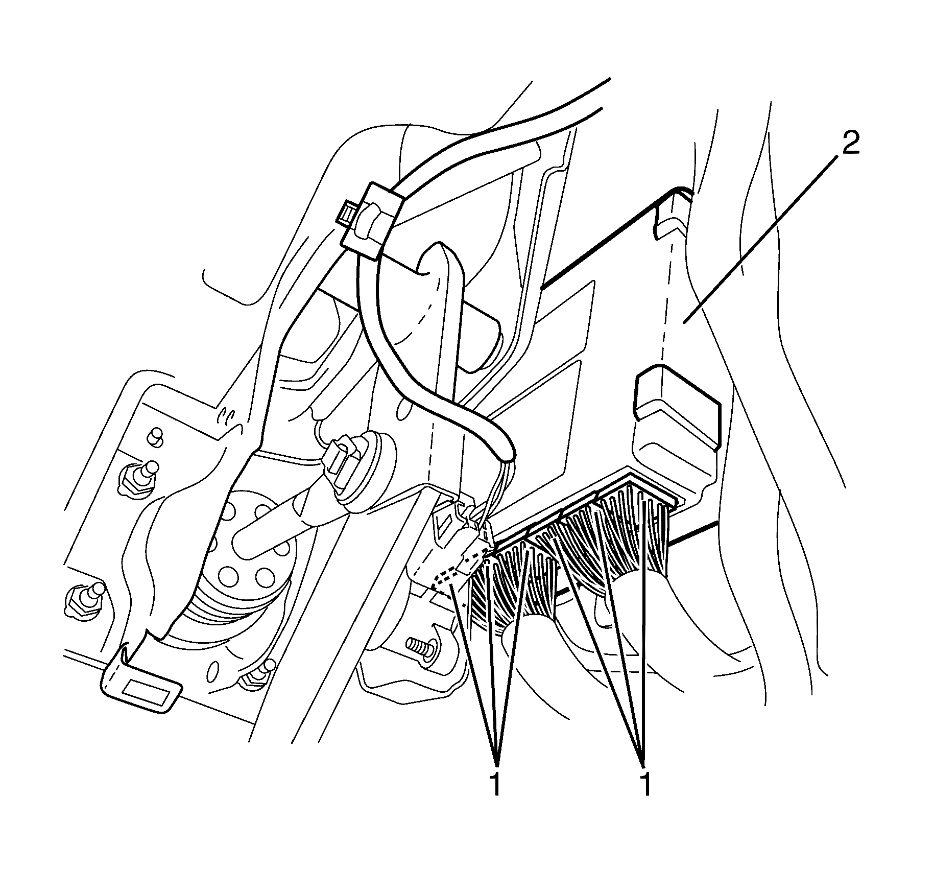
- Disconnect the body control module (BCM) electrical connectors (1) from the BCM (2).
- Remove the BCM (3).
Caution: Refer to SIR Caution in the Preface section.
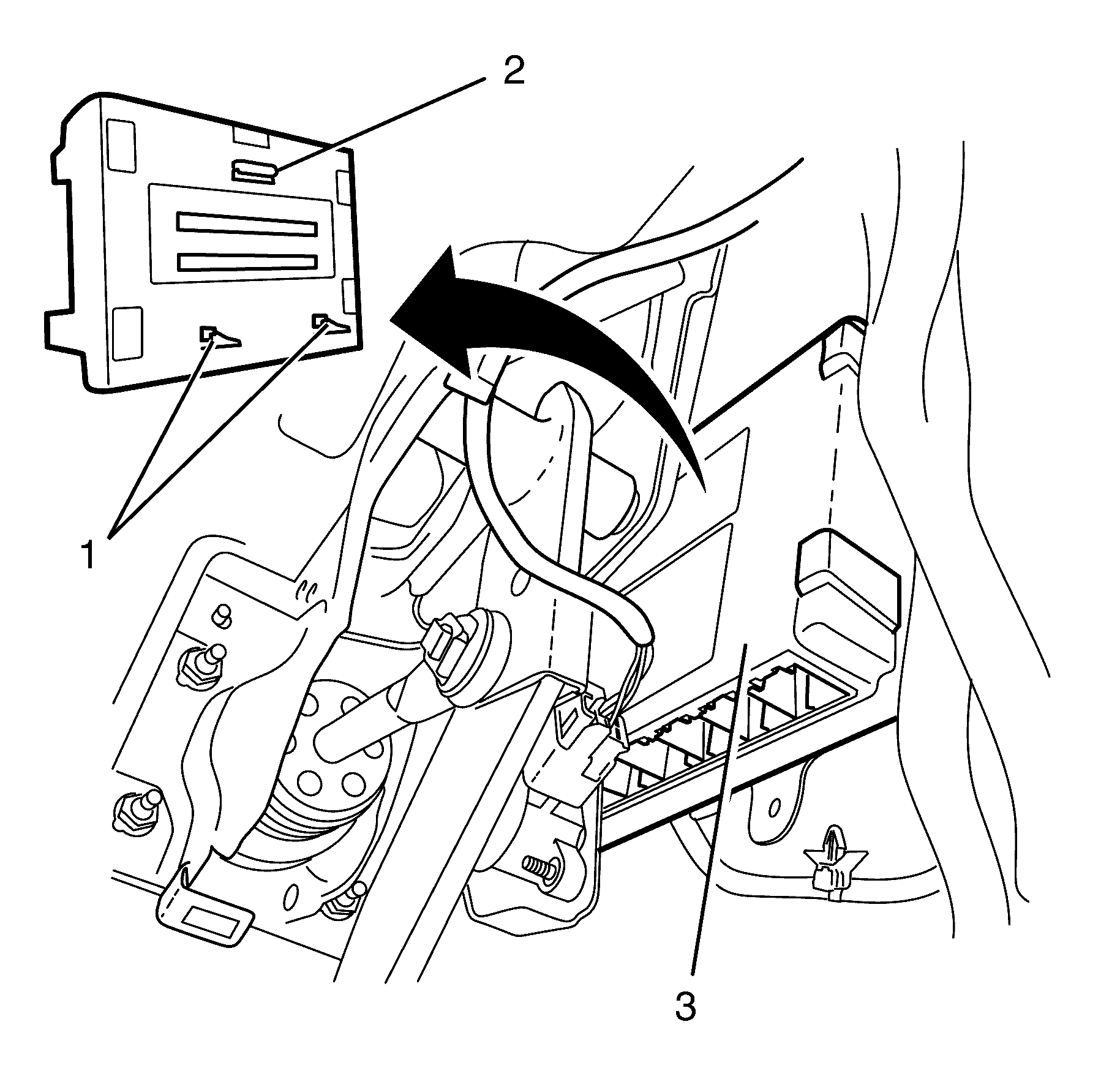
Important: Release the lower retaining clips (1), lift the BCM and unhook the upper retaining clip (2).
Installation Procedure
- Install the BCM (3).
- Connect the body control module (BCM) electrical connectors (1) to the BCM (2).
- Install the instrument panel retainer. Refer to Instrument Panel Retainer Replacement .
- Install the knee bolster. Refer to Knee Bolster Replacement .
- Install the right closeout insulator panel. Refer to Instrument Panel Insulator Panel Replacement - Right Side .
- Enable the SIR system. Refer to SIR Disabling and Enabling .
- Connect the negative battery cable. Refer to Battery Negative Cable Disconnection and Connection .
- Re-programme the (BCM). Refer to Body Control Module Programming and Setup .
Important: Locate the upper retaining clip (2) and engage the lower retaining clips (1).
Caution: Refer to SIR Caution in the Preface section.
Body Control Module Replacement LHD
Removal Procedure
- Disconnect the negative battery cable. Refer to Battery Negative Cable Disconnection and Connection .
- Disable the SIR system. Refer to SIR Disabling and Enabling .
- Remove the left closeout insulator panel. Refer to Instrument Panel Insulator Panel Replacement - Left Side .
- Remove the knee bolster. Refer to Knee Bolster Replacement ..
- Remove the instrument panel retainer. Refer to Instrument Panel Retainer Replacement ..
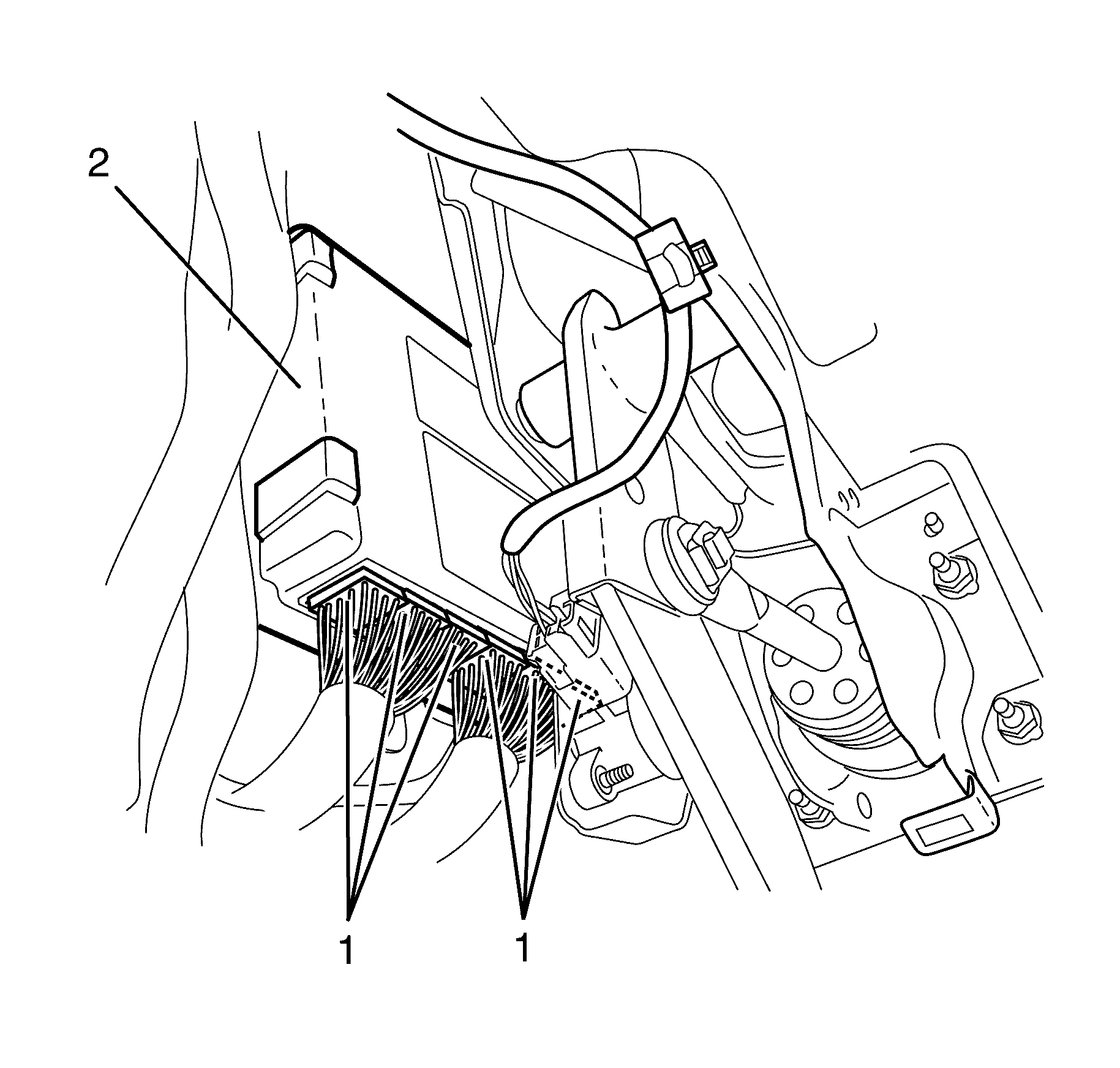
- Disconnect the body control module (BCM) electrical connectors (1) from the BCM (2).
- Remove the BCM (3).
Caution: Refer to SIR Caution in the Preface section.
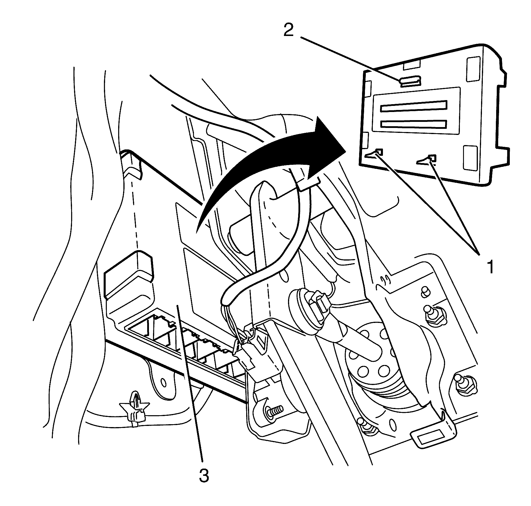
Important: Release the lower retaining clips (1), lift the BCM and unhook the upper retaining clip (2).
Installation Procedure
- Install the BCM (3).
- Connect the body control module (BCM) electrical connectors (1) to the BCM (2).
- Install the instrument panel retainer. Refer to Instrument Panel Retainer Replacement .
- Install the knee bolster. Refer to Knee Bolster Replacement .
- Install the left closeout insulator panel. Refer to Instrument Panel Insulator Panel Replacement - Left Side .
- Enable the SIR system. Refer to SIR Disabling and Enabling .
- Connect the negative battery cable. Refer to Battery Negative Cable Disconnection and Connection .
Important: Locate the upper retaining clip (2) and engage the lower retaining clips (1).
Caution: Refer to SIR Caution in the Preface section.
