Oil Pan Replacement RHD
Removal Procedure
- Disconnect the battery ground cable. Refer to Battery Negative Cable Disconnection and Connection .
- Raise and support the vehicle. Refer to Lifting and Jacking the Vehicle .
- Drain the engine oil. Refer to Engine Oil and Oil Filter Replacement .
- Remove the engine splash shield. Refer to Engine Splash Shield Replacement .
- Remove the front air deflector. Refer to Front Air Deflector Replacement .
- Mark the intermediate steering shaft (1) in relation to the pinion shaft (3) and discard.
- Remove the intermediate steering shaft to pinion shaft retaining bolt (2).
- Disconnect the intermediate shaft (2) from the pinion shaft (3).
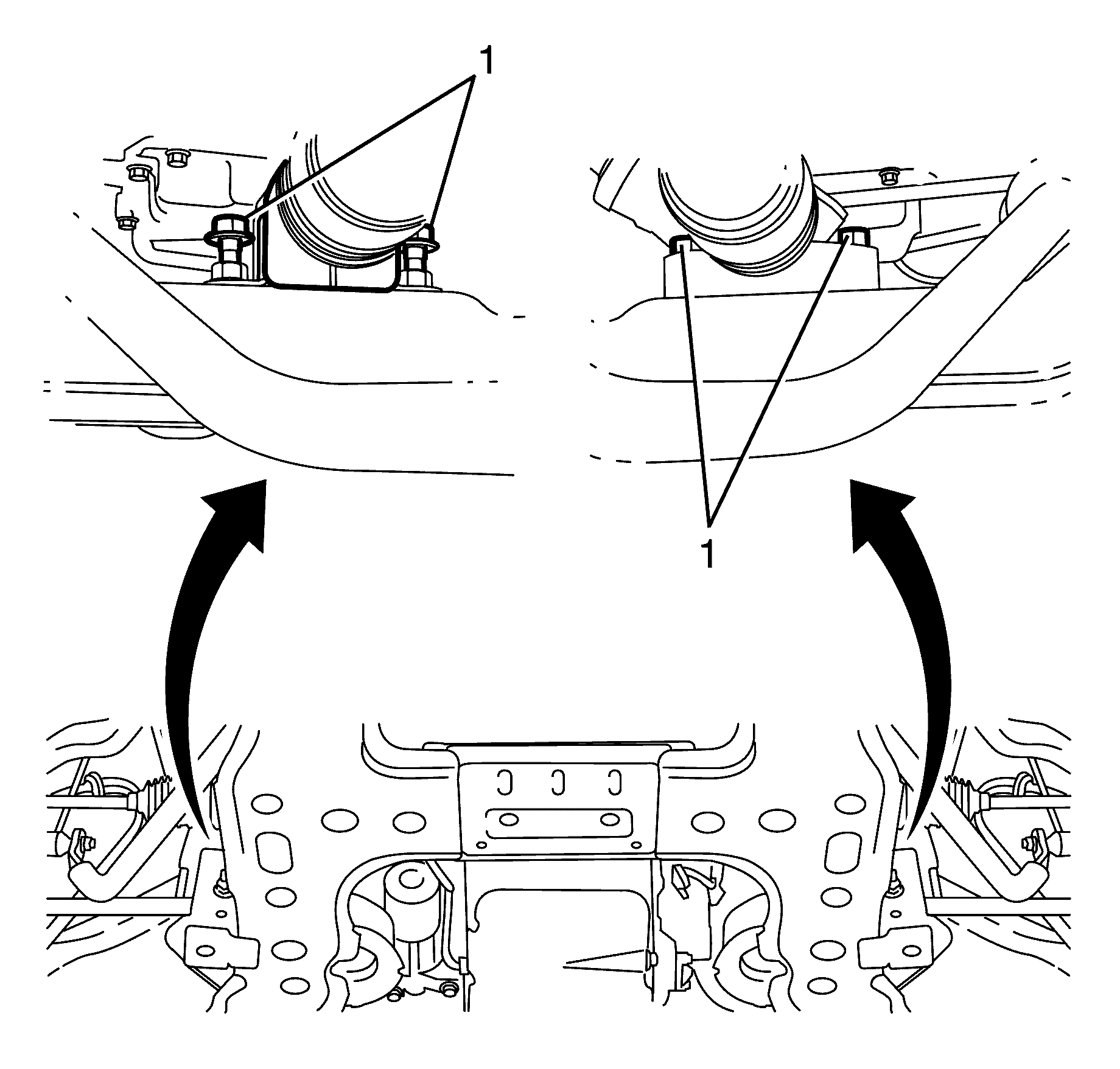
- Remove the steering gear to subframe retaining bolts (1).
- Slide the steering gear forward to gain full access to the sump.
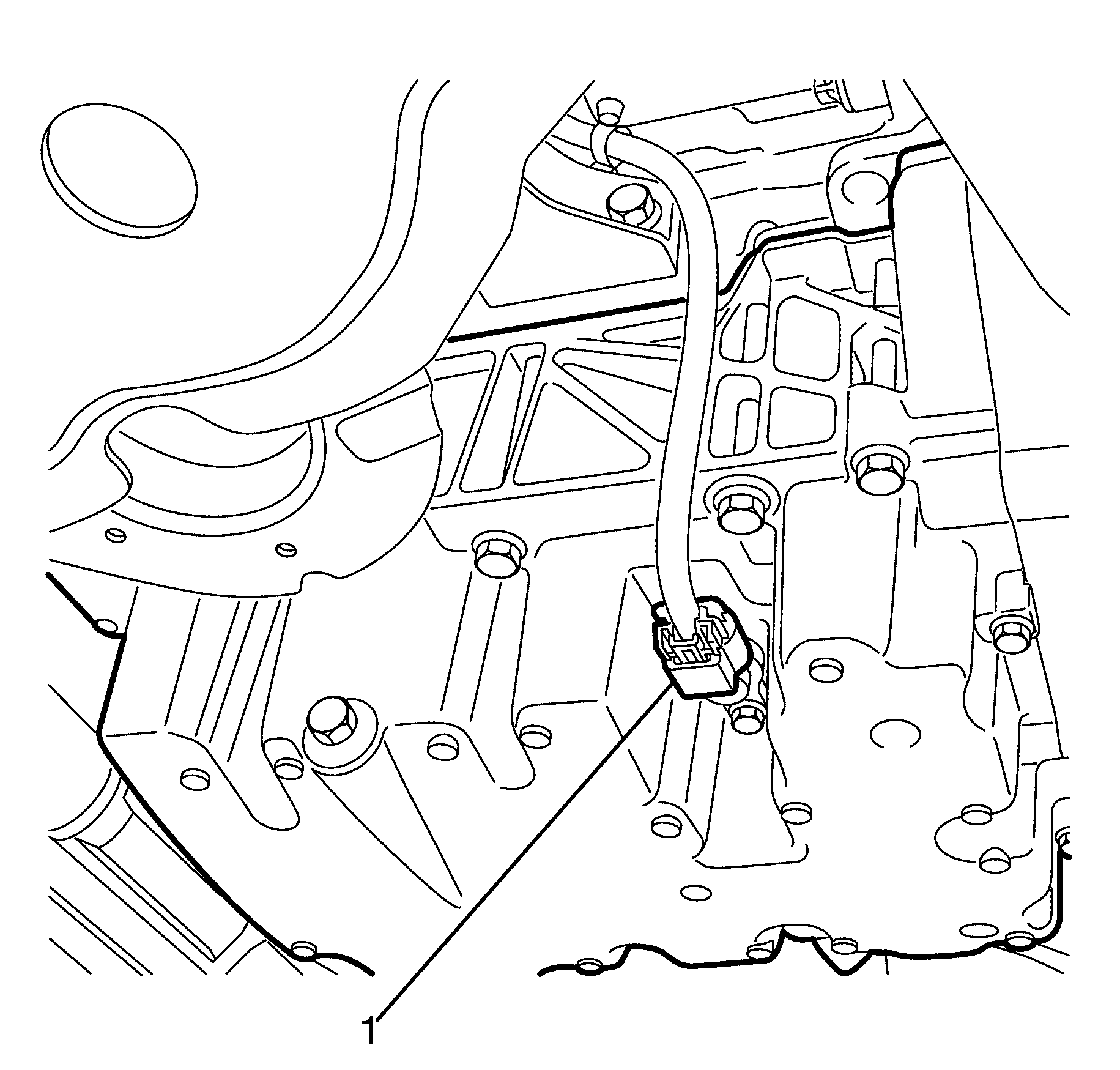
- Disconnect the oil level/temperature sensor electrical connector (1).
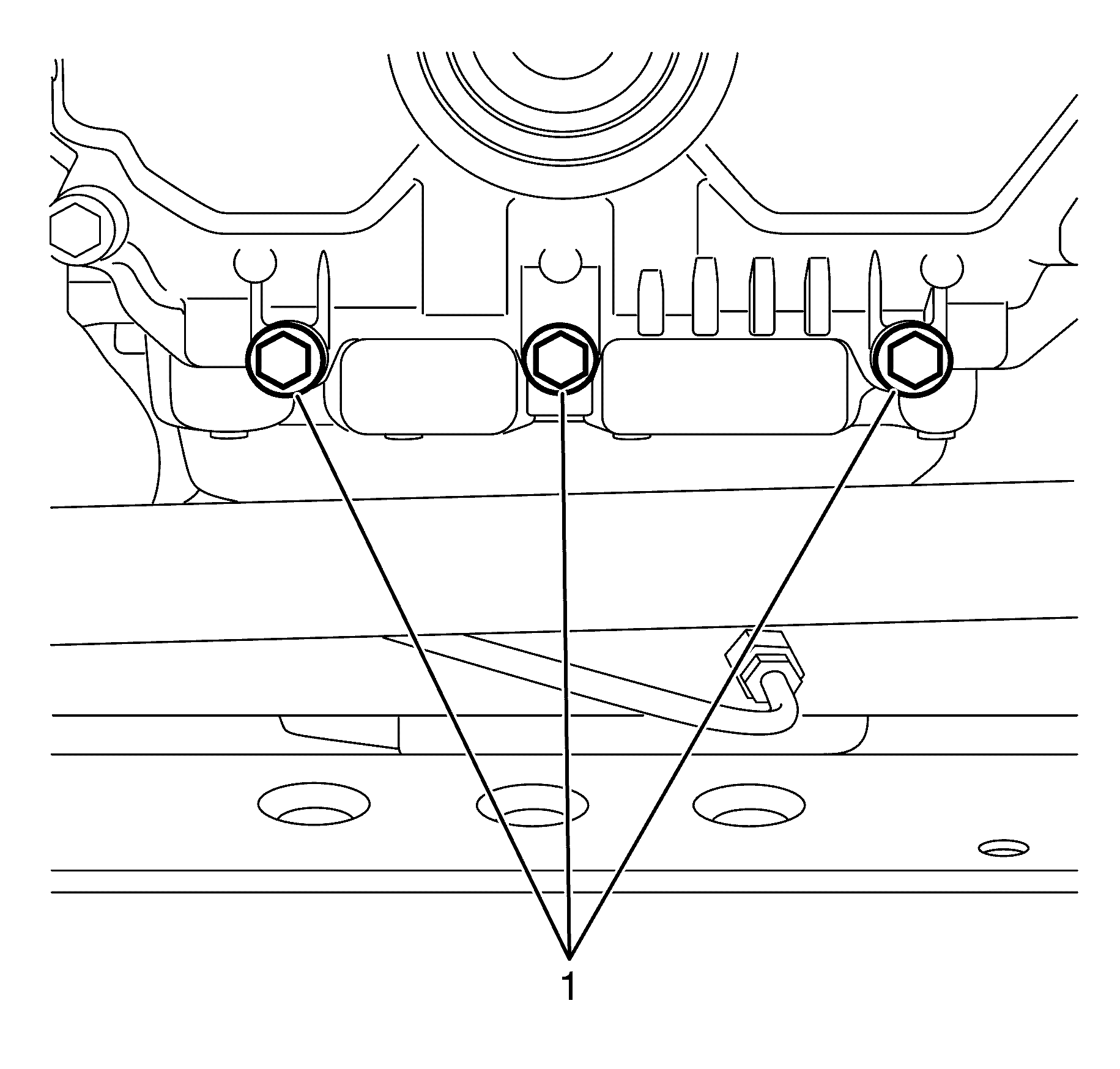
- Remove the front cover to oil pan retaining bolts (1).
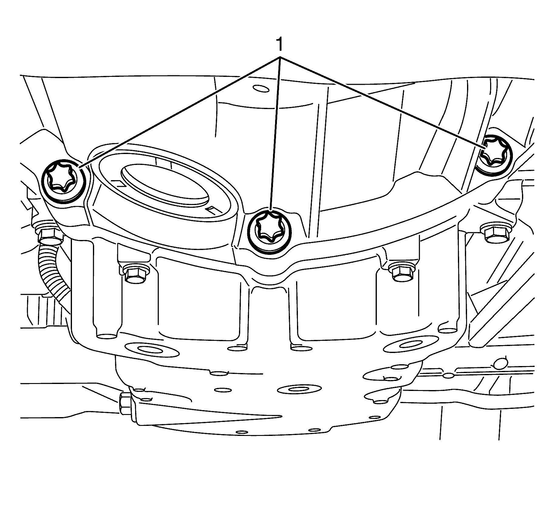
- Remove the transmission to oil pan retaining bolts (1).
- Remove the M6 rear oil pan to ccrankshaft rear oil seal housing retaining bolts (4).
- Remove the M8 oil pan to cylinder block retaining bolts (5).
- Remove the oil pan (2) from the cylinder block.
- Perform the following steps as necessary.
Caution: Refer to Battery Disconnect Caution in the Preface section.
Caution: Refer to Safety Glasses Caution in the Preface section.
Caution: Refer to Vehicle Lifting Caution in the Preface section.
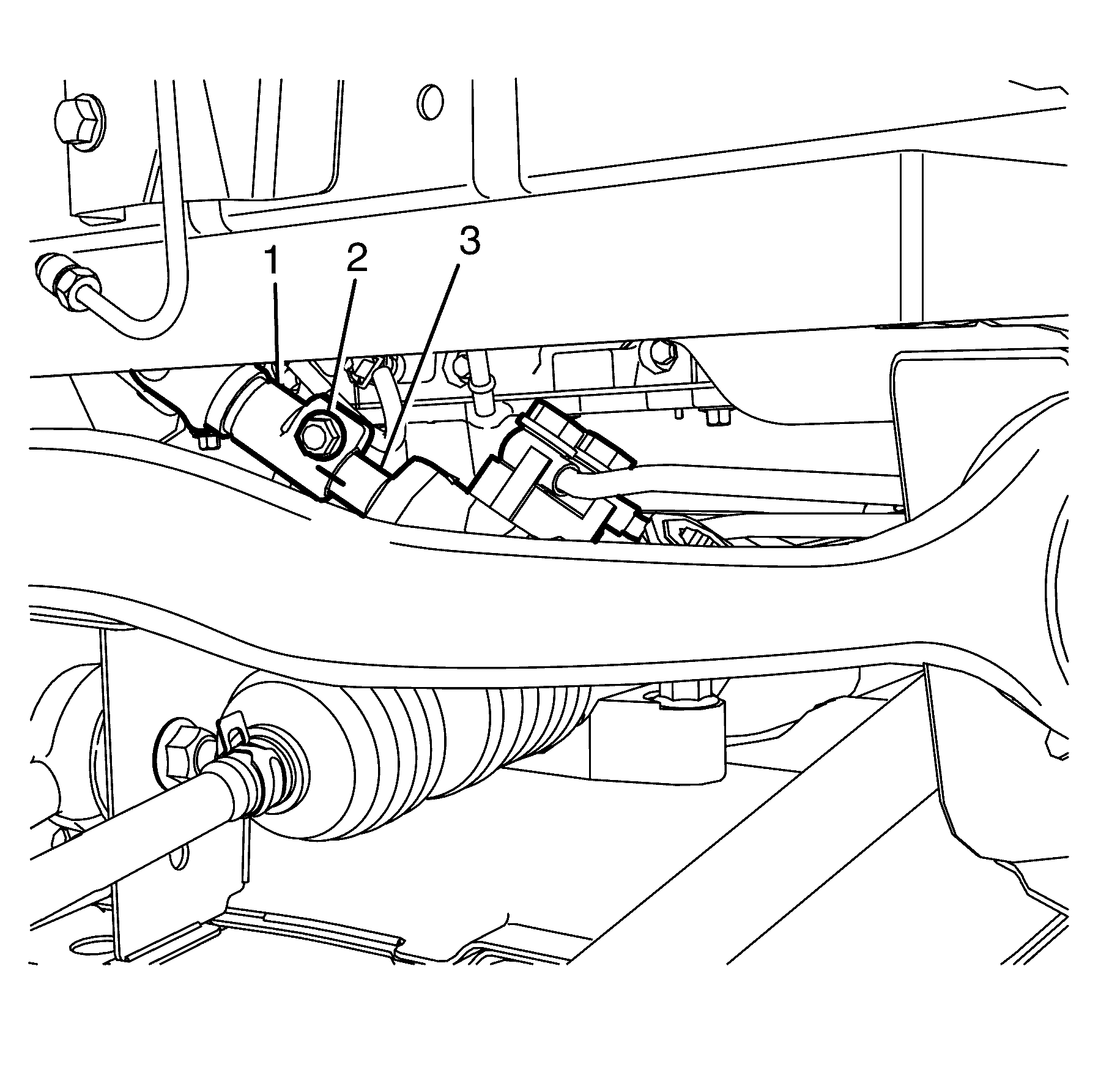
Important: Observing the orientation of the intermediate steering shaft (1) with reference to the pinion shaft (3) will minimise the potential of incorrect steering column assembly alignment.
Important: Bolts with micro-encapsulated thread sealant must be discarded after removal.
Discard the bolt.
Important: Make sure the bolt hole is thoroughly cleaned and all micro-encapsulated thread sealant is removed.
Clean the bolt hole.
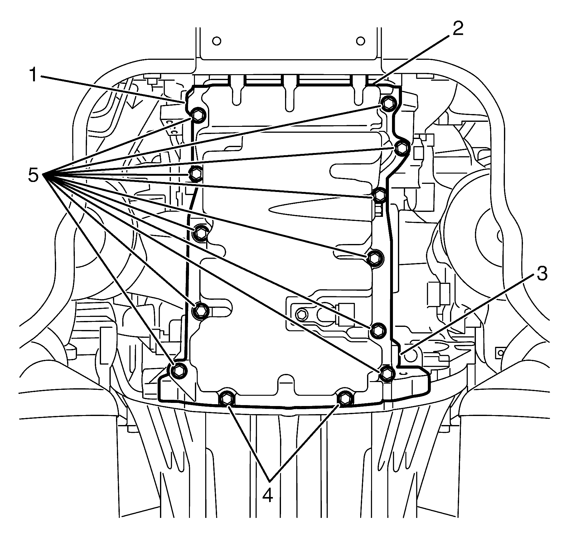
Important: Using the pry points (1 and 3) to shear the RTV sealant.
| • | Disassemble the oil pan. Refer to Oil Pan Disassemble . |
| • | Clean and inspect the oil pan. Refer to Oil Pan Cleaning and Inspection . |
Installation Procedure
- Assemble the oil pan as necessary. Refer to Oil Pan Assemble .
- Place a three mm (0.118 in) bead of RTV sealant (1) on the block pan rail and the crankshaft rear oil seal housing.
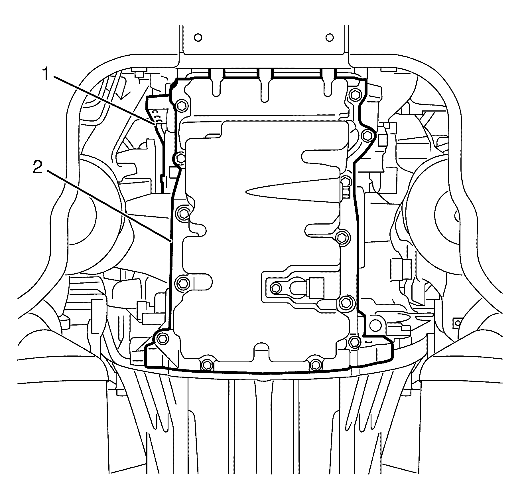
- Position the oil pan (1) onto the engine block (2).
- Install the M8 oil pan to cylinder block retaining bolts (1-11).
- Install the M6 oil pan to crankshaft rear oil seal housing retaining bolts (12, 13).
- Tighten the M8 oil pan to cylinder block retaining bolts (1-11) and M6 oil pan to crankshaft rear oil seal housing retaining bolts (12, 13) in the sequence shown.
- Install the transmission to oil pan retaining bolts (1).
- Install the front cover to oil pan retaining bolts (1).
- Connect the oil level/temperature sensor electrical connector (1) to the oil level/temperature sensor.
- Position the steering gear in the correct location.
- Install the steering gear to subframe retaining bolts (1).
- Connect the intermediate steering shaft (1) to the pinion shaft (3).
- Install the NEW intermediate steering shaft to pinion shaft retaining bolt (2).
- Install the engine splash shield. Refer to Engine Splash Shield Replacement .
- Install the front air deflector. Refer to Front Air Deflector Replacement .
- Lower the vehicle to the ground
- Fill the engine with new engine oil. Refer to Engine Oil and Oil Filter Replacement .
- Connect the battery ground cable. Refer to Battery Negative Cable Disconnection and Connection .
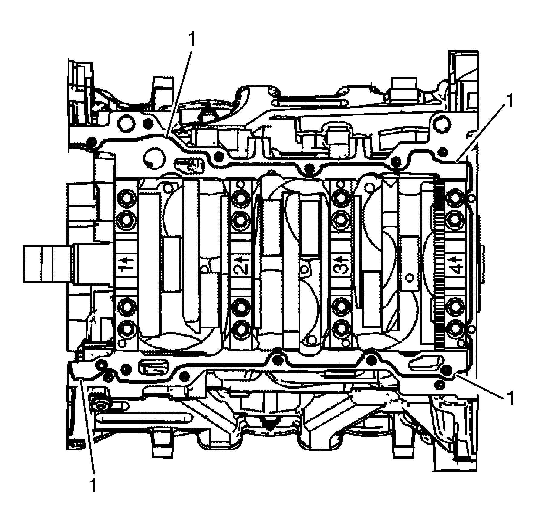
Notice: Refer to Fastener Notice in the Preface section.
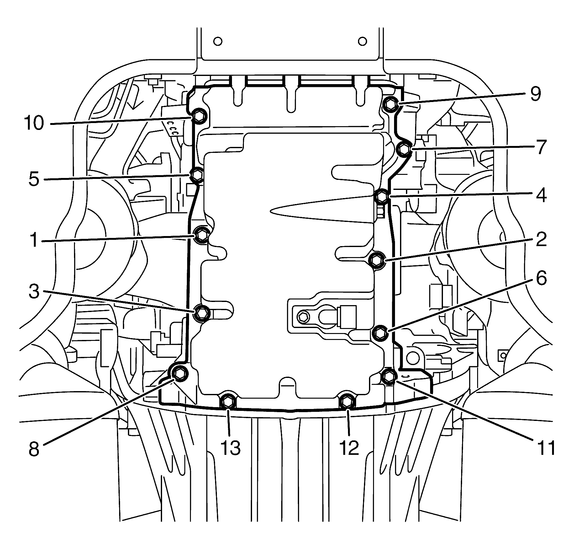
Tighten
Tighten the M6 bolts (12, 13) to 10 N·m
(89 lb in).
Tighten
Tighten the M8 bolts (1-11) to 23 N·m
(17 lb ft).

Tighten
Tighten the bolts to 48 N·m (17 lb ft).

Tighten
Tighten the bolts to 23 N·m (17 lb ft).


Tighten
Tighten the Bolts to 65 N·m (48 lb ft).

Important: The intermediate steering shaft and pinion shaft splines must be installed in the position recorded during removal and aligned with the marks previously made.
Tighten
Tighten the bolt to 25 N·m (16 lb ft).
