Rear Bumper Fascia Center Support Replacement Sportwagon
Removal Procedure
- Disable the SIR system. Refer to SIR Disabling and Enabling.
- Disconnect the negative battery cable. Refer to Battery Negative Cable Disconnection and Connection.
- Remove the rear compartment floor panel carpet. Refer to Rear Compartment Floor Panel Carpet Replacement
- Remove the rear end trim finish panel. Refer to Rear End Trim Finish Panel Replacement
- Remove the liftgate weatherstrip. Refer to Liftgate Weatherstrip Replacement.
- Raise and support the vehicle. Refer to Lifting and Jacking the Vehicle.
- Remove the rear bumper fascia. Refer to Rear Bumper Fascia Replacement.
- Remove the rear bumper impact bar. Refer to Rear Bumper Impact Bar Replacement.
- Remove the sealers and anti-corrosion materials from the repair area, as necessary. Refer to Anti-Corrosion Treatment and Repair.
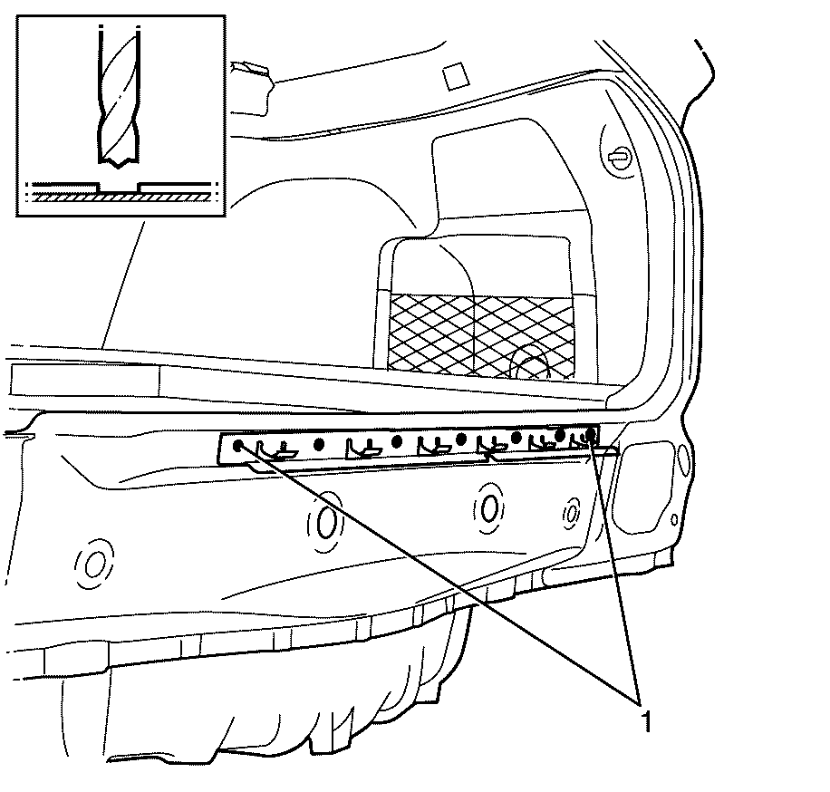
- Locate, mark and drill out the spot welds in the rear bumper fascia centre support to the rear end panel assembly (1).
Caution: Refer to Approved Equipment for Collision Repair Caution in the Preface section.
Caution: Refer to Safety Glasses Caution in the Preface section.
Caution: Refer to Foam Sound Deadeners Caution in the Preface section.
Caution: Refer to Battery Disconnect Caution in the Preface section.

Installation Procedure
- Drill 8 mm (5/16 in) plug weld holes as necessary in the locations noted when disassembling.
- Clean and prepare the mating surfaces of both parts of the panel.
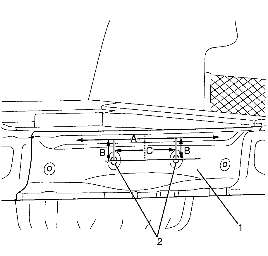
- Utilising the two holes in the rear end panel assembly (2) as a reference point, mark the centre line of the vehicle (C) onto the rear end panel assembly (1).
- Utilising the two holes in the rear end panel assembly (2) as a reference point, measure 57.5 mm (B) above each hole onto the rear end panel assembly (1) to establish the rear bumper fascia centre support location alignment mark (A).
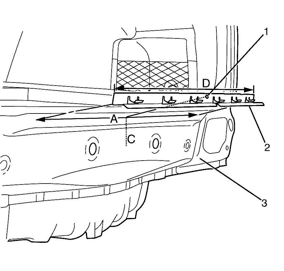
- Measure and mark the centre point on the bumper facia centre support assembly (D).
- Align the centre point mark on the rear bumper facia centre support assembly (1) with the centre line mark on the rear end panel assembly (C).
- Align the lower edge of the rear bumper facia centre support assembly (2) with the alignment marks (A) on the rear end panel assembly (3).
- Weld the centre support assembly (2) to the rear end panel assembly (3).
- Apply the sealers and anti-corrosion materials to the repair area, as necessary. Refer to Anti-Corrosion Treatment and Repair.
- Paint the repaired area. Refer to Basecoat/Clearcoat Paint Systems.
- Install the rear bumper impact bar. Refer to Rear Bumper Impact Bar Replacement.
- Install the rear bumper fascia. Refer to Rear Bumper Fascia Replacement.
- Lower the vehicle.
- Install the liftgate weatherstrip. Refer to Liftgate Weatherstrip Replacement.
- Install the rear end trim finish panel. Refer to Rear End Trim Finish Panel Replacement
- Install the rear compartment floor panel carpet. Refer to Rear Compartment Floor Panel Carpet Replacement
- Connect the negative battery cable. Refer to Battery Negative Cable Disconnection and Connection.
- Enable the SIR system. Refer to SIR Disabling and Enabling.
Important: Spot welding is the preferred method for attaching panels and should be used whenever possible. A plug weld should only be performed where spot welding is not possible.
Important: If the location of the original spot weld holes cannot be determined, or if structural weld-thru adhesive is present, space the puddle weld holes every 32 mm (1¼ in).
Important: Follow the adhesive manufacturer's instructions during the assembly process. Heat must be applied as per the manufacturer's specifications to cure the adhesives and to expand the sealing baffles.


Important: Secondary sealer must be applied to the perimeter of all flanges. Secondary sealer must be applied to all welds/joints that were originally covered by secondary sealer.
