Exhaust Manifold Replacement 2.4L
Removal Procedure
- Disconnect the negative battery cable.
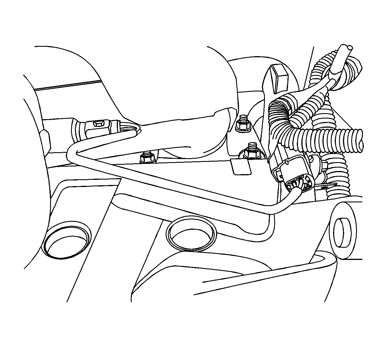
- Disconnect the front heated oxygen sensor connector.
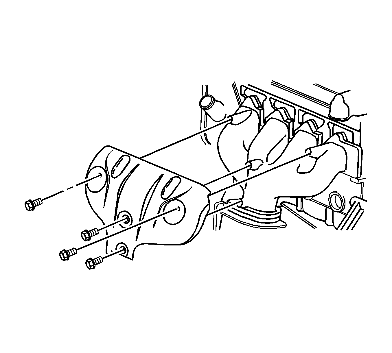
- Remove the exhaust manifold heat shield retaining bolts.
- Remove the exhaust manifold heat shield retaining bolts.
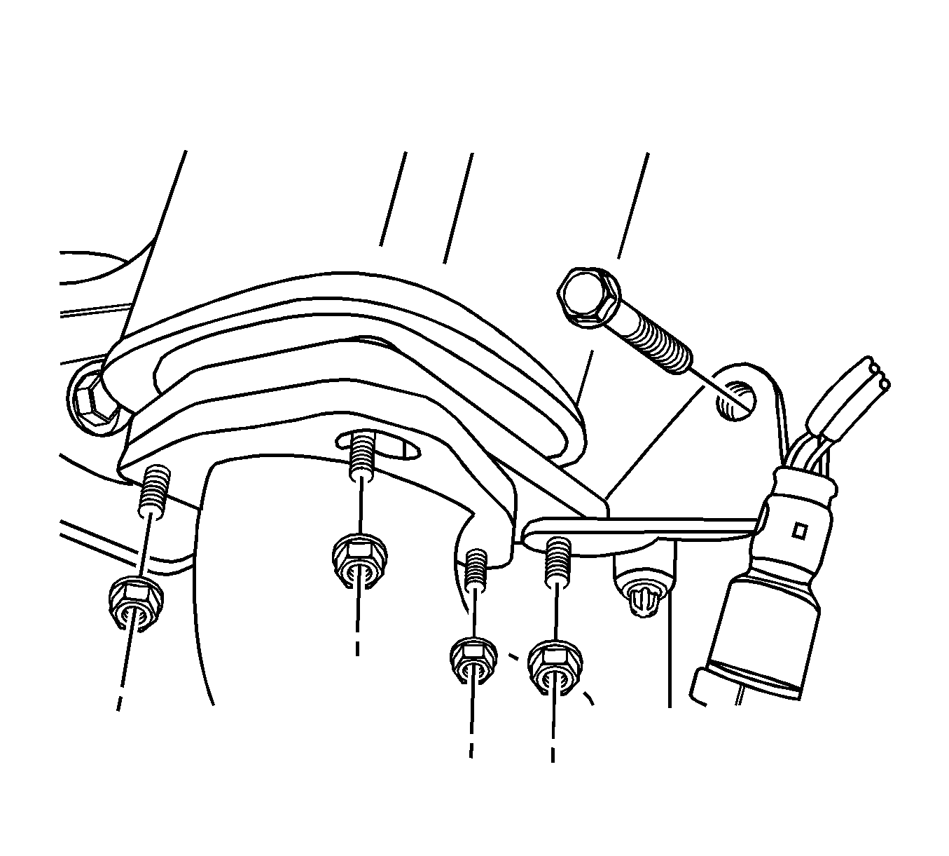
- Remove the pup converter-to-exhaust front pipe retaining nuts.
- Remove the exhaust front pipe mounting bracket bolt and nut.
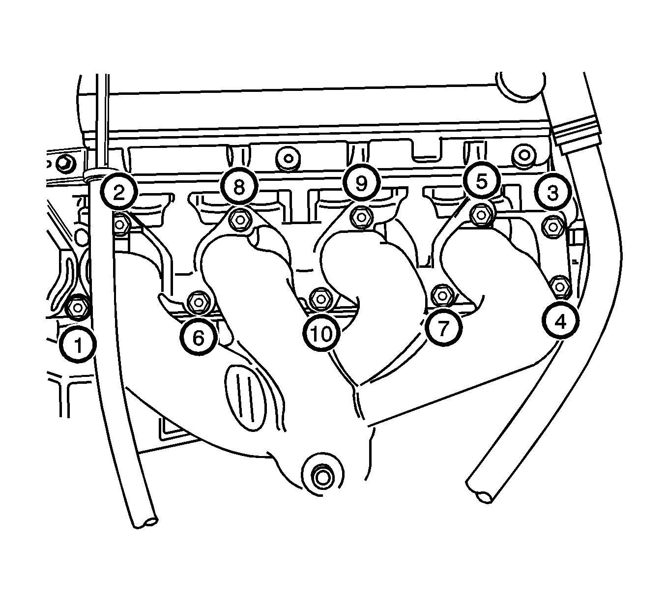
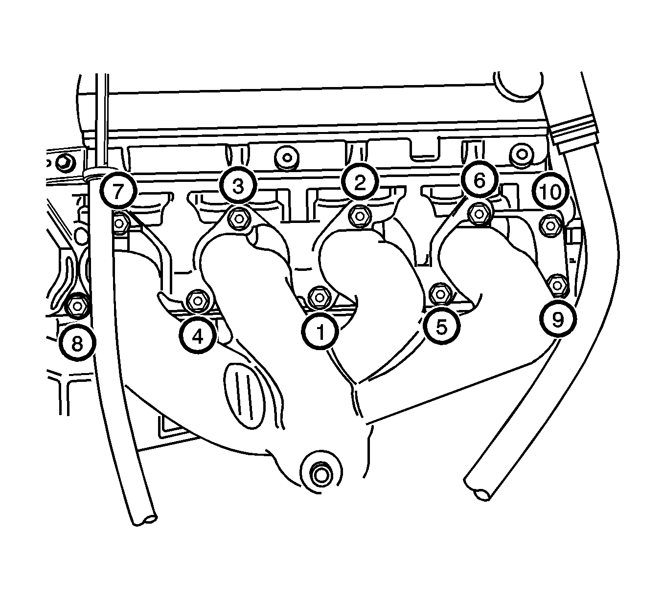
- Remove the exhaust manifold retaining nuts in the sequence shown.
- Remove the exhaust manifold.
- Remove the exhaust manifold gasket.
- Clean the sealing surfaces of the exhaust manifold and the cylinder head.
Caution: Refer to Battery Disconnect Caution in the Preface section.
Installation Procedure
- Install a new exhaust manifold gasket.
- Install the exhaust manifold.
- Install the exhaust manifold retaining nuts and tighten in the sequence shown.
- Install the exhaust front pipe-to-pup converter. Refer to Front Pipe Replacement .
- Install the exhaust manifold heat shield.
- Connect the front heated oxygen sensor connector.
- Connect the negative battery cable.
Notice: Refer to Fastener Notice in the Preface section.
Tighten
Tighten the exhaust manifold retaining nuts to 22 N·m (16 lb ft).

Tighten
| • | Tighten the pup converter-to-exhaust front pipe retaining nuts to 40 N·m (30 lb ft). |
| • | Tighten the exhaust front pipe mounting bracket bolt and nut to 40 N·m (30 lb ft). |

Tighten
Tighten the exhaust manifold heat shield bolts to 15 N·m (11 lb ft).

Exhaust Manifold Replacement 2.0L Diesel
Removal Procedure
- Disconnect the negative battery cable
- Remove the engine cover. Refer to Engine Cover Replacement .
- Remove the charge air system hoses and ducts. Refer to Charge Air Cooler Inlet Pipe and Outlet Pipe Replacement .
- Remove the PCV valve and adapter. Refer to Positive Crankcase Ventilation Valve Replacement and Positive Crankcase Ventilation Hose/Pipe/Tube Replacement .
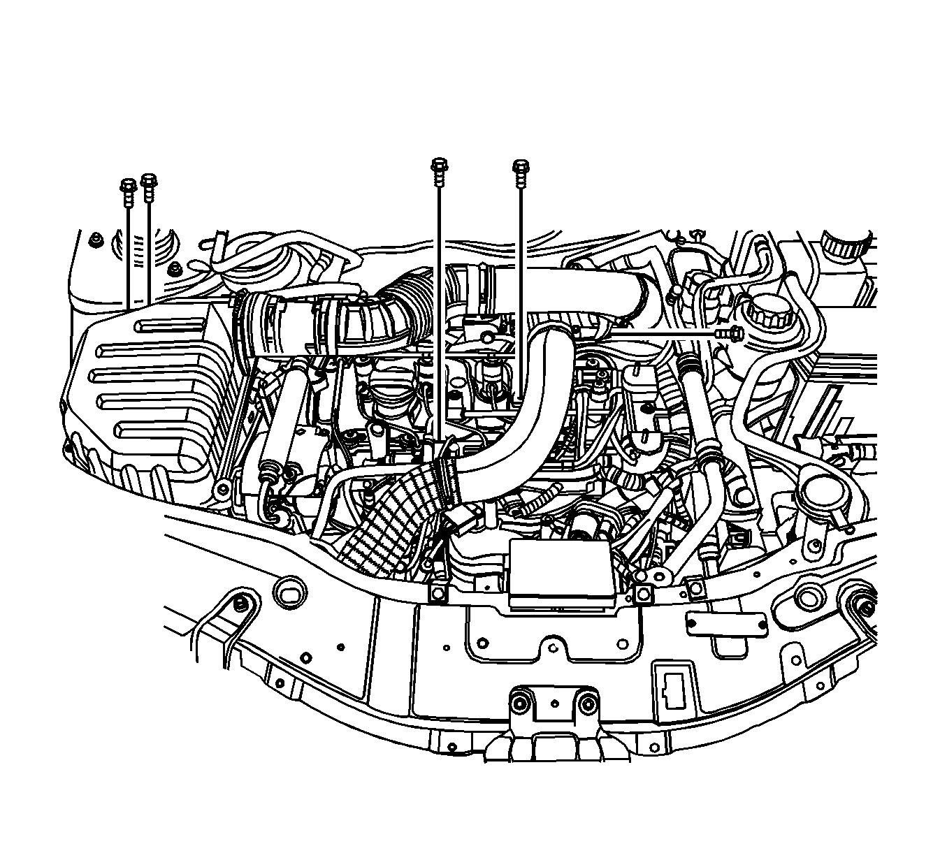
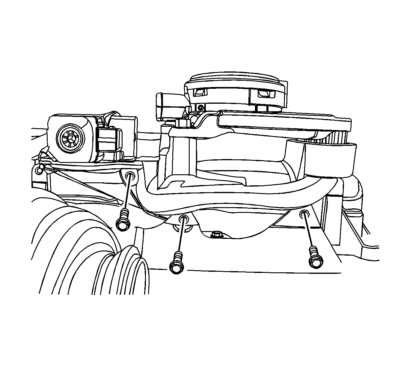
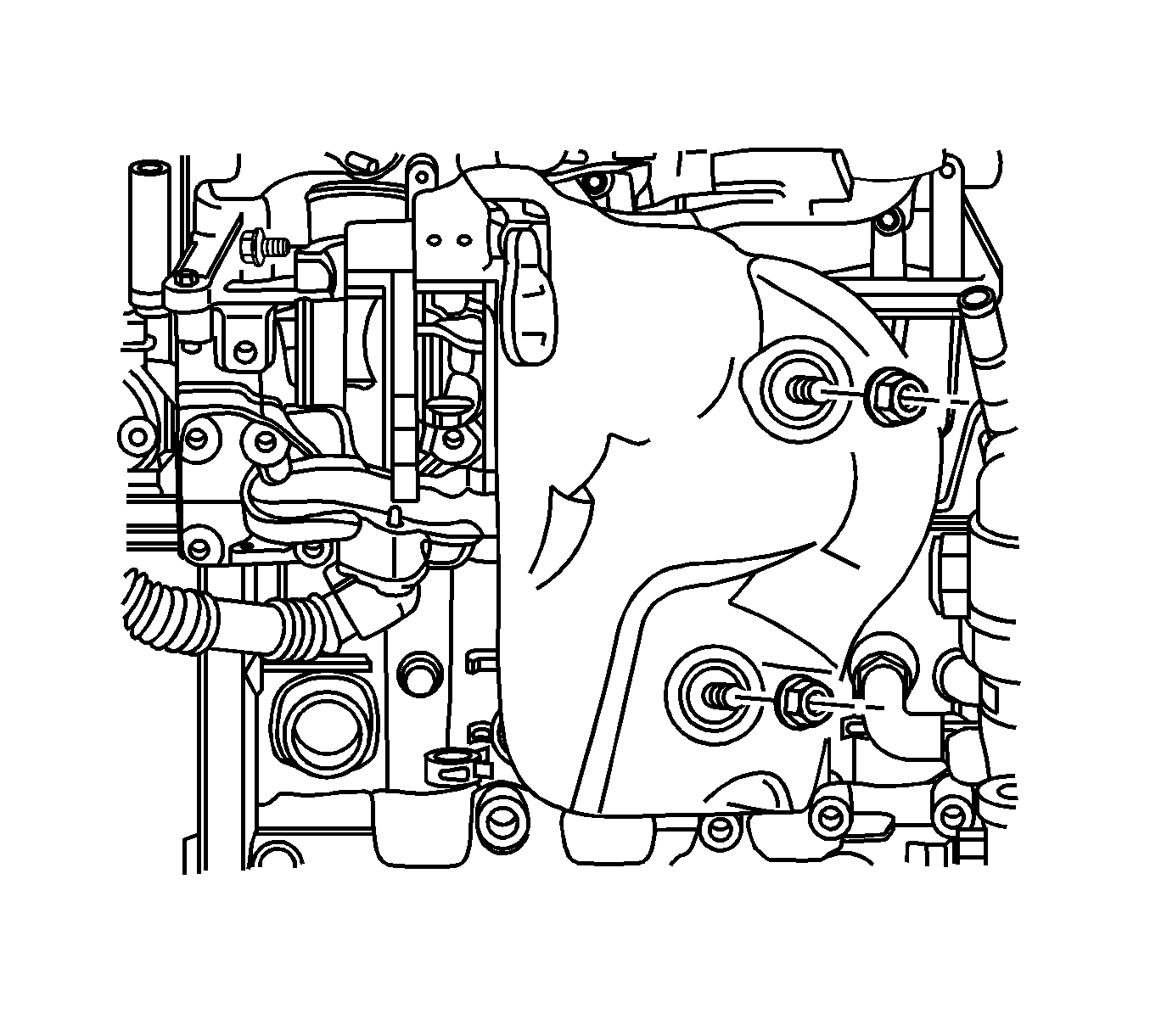
- Remove the exhaust heat shield.
- Remove the pre-catalyst. Refer to Catalytic Converter Replacement .
- Remove the turbocharger from the exhaust manifold. Refer to Turbocharger Replacement .
- Remove the EGR cooler inlet pipe from the EGR valve with the gasket.
- Remove the exhaust manifold with the EGR cooler inlet pipe.
- Remove the EGR cooler inlet pipe from the exhaust manifold.
Caution: Refer to Battery Disconnect Caution in the Preface section.
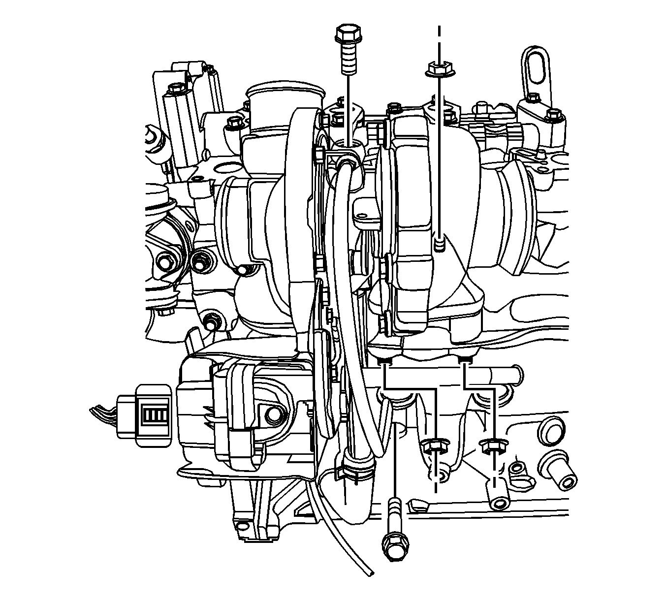
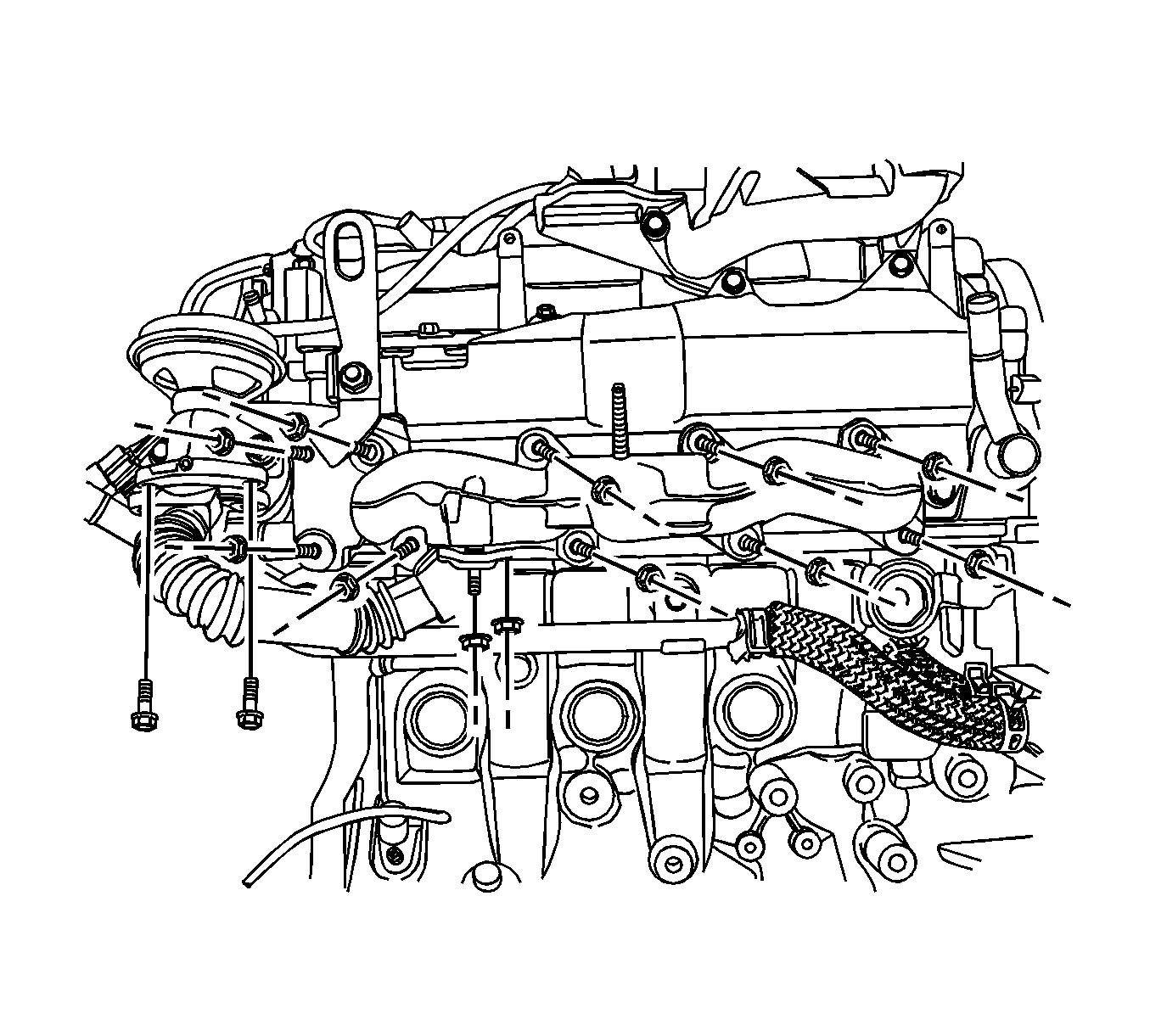
Installation Procedure
- Install the EGR cooler inlet pipe to the exhaust manifold.
- Install the exhaust manifold to the cylinder head with a new gasket.
- Install the EGR cooler inlet pipe to the EGR valve with a new gasket.
- Install the exhaust manifold heat shield.

Notice: Refer to Fastener Notice in the Preface section.
Tighten
| • | Tighten the EGR cooler inlet pipe nuts (to exhaust manifold) to 33 N·m (24.3 lb ft). |
| • | Tighten the exhaust manifold nuts to 33 N·m (24.3 lb ft). |
| • | Tighten the EGR cooler inlet pipe bolts (to EGR valve) to 20 N·m (14.8 lb ft). |

Tighten
Tighten the exhaust manifold heat shield nuts and bolt to 20 N·m (14.8 lb ft).
Exhaust Manifold Replacement 3.2L
Removal Procedure
- Disconnect the negative battery cable.
- Remove the exhaust front pipe. Refer to Front Pipe Replacement.
- Remove the pup converter. Refer to Catalytic Converter Replacement.
- For the bank 1 exhaust manifold, remove the transfer case. Refer to Transfer Case Assembly Replacement.
- For the bank 1 exhaust manifold, remove the transaxle rear mount assembly. Refer to Engine Mount Replacement - Left Side.
- Disconnect the upper heated oxygen sensor connector.
- Remove the three bolts (1) attaching the exhaust manifold outer heat shield (2) to the exhaust manifold.
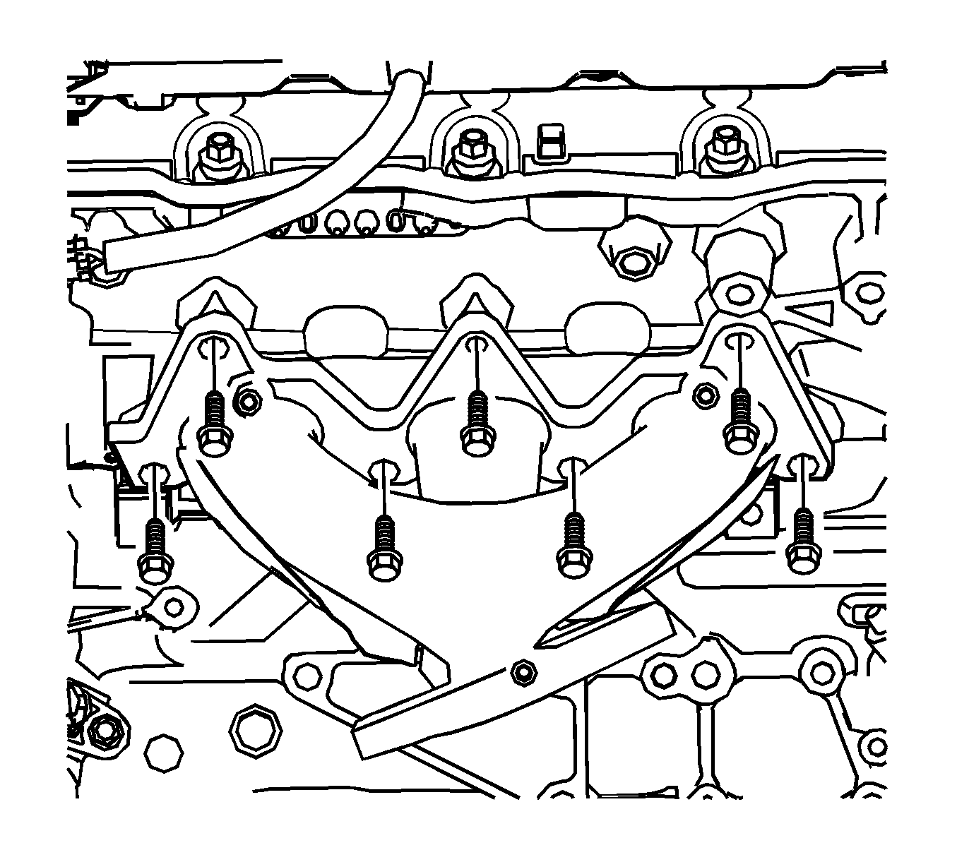
- Progressively loosen the seven exhaust manifold attaching bolts, working from the outside to the center and then remove the bolts.
- Remove and discard the exhaust manifold to cylinder head gasket.
- Remove the three bolts attaching the exhaust manifold inner heat shield from the exhaust manifold, if necessary.
Caution: Refer to Battery Disconnect Caution in the Preface section.
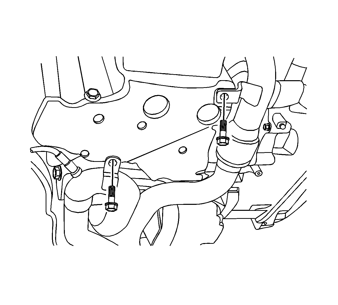
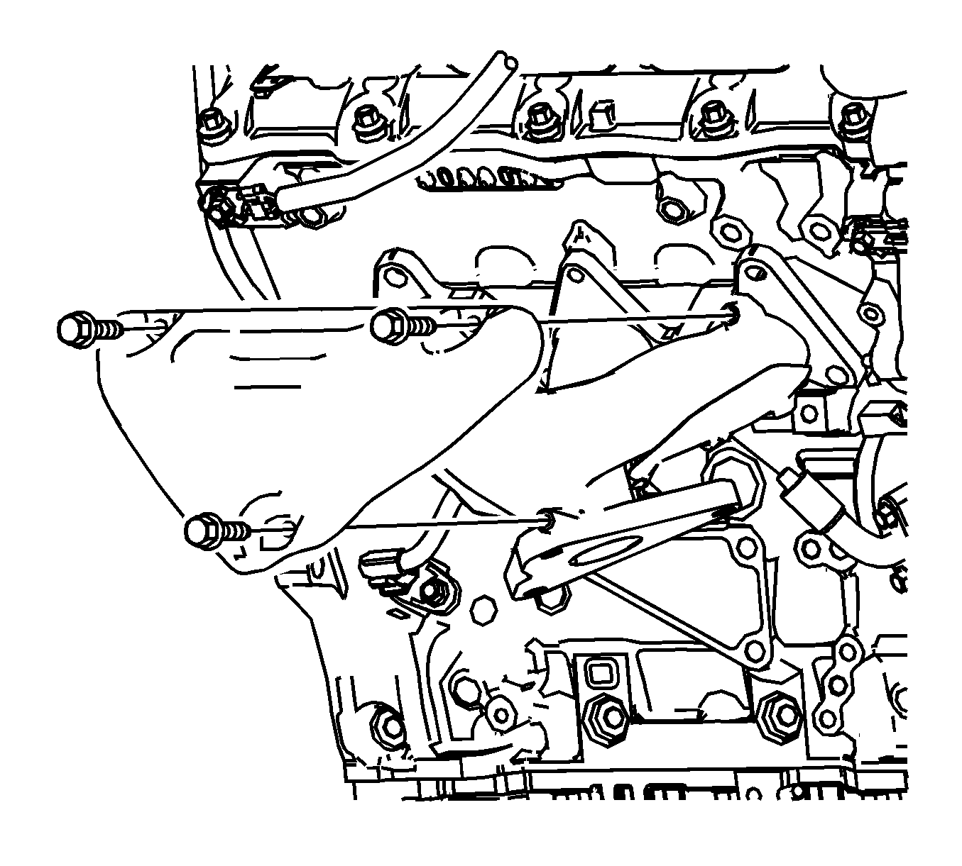
Cleaning Procedure
- Using a suitable commercially available non-corrosive cleaning solvent and a soft bristled parts cleaning brush, thoroughly clean the exhaust manifold.
- Dry the exhaust manifold using compressed air.
Inspection Procedure
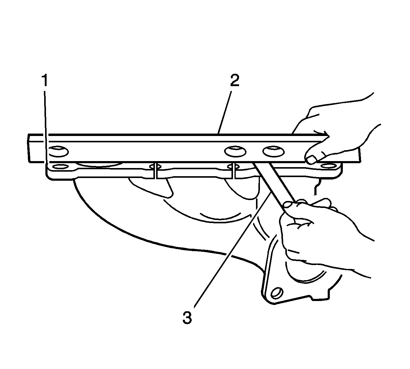
- Inspect the exhaust manifold (1) for the following:
- Using a straight (2) and feeler gages (3), check the cylinder head mounting face of the exhaust manifold does not exceed the maximum distortion specification of 0.25 mm.
| • | Damage to the threaded holes for the heat shield mounting. |
| • | Damage to the exhaust manifold mounting holes. |
| • | Damage to the threads of the exhaust manifold to exhaust pipe flange studs. |
| • | Damage to the gasket sealing surfaces. |
Important: If the surface flatness is not within specifications, the exhaust manifold is warped and must be replaced.
Installation Procedure
- Install the exhaust manifold inner heat shield to the exhaust manifold, if necessary.
- Position a new exhaust manifold gasket onto the exhaust manifold.
- Apply Loctite 272 thread sealant (or equivalent) to the threads of the exhaust manifold attaching bolts.
- Maneuver the exhaust manifold into position and install the exhaust manifold attaching bolts
- Install the exhaust manifold heat shield.
- Install the other parts that were previously removed.
Notice: Refer to Fastener Notice in the Preface section.

Tighten
Tighten the exhaust manifold inner heat shield attaching bolt to 10 N·m (89 lb in).
Important: When tightening the exhaust manifold to cylinder head attaching bolts, begin with the center bolts, then alternate from side to side to the outer bolts.
Tighten
Tighten the exhaust manifold-to-cylinder head attaching bolts to 20 N·m (15 lb ft).

Tighten
Tighten the exhaust manifold outer heat shield attaching bolts to 10 N·m (89 lb in).
