Tools Required
| • | OTC 1726 Engine Overhaul Stand |
| • | KM-470-B Angular Torque Gauge |
Disassembly Procedure
- Remove the engine. Refer to Engine Replacement
- Remove the flywheel or flexible plate bolts.
- Remove the flywheel or flexible plate.
- Remove the crankshaft rear oil seal.
- Mount the engine assembly using the OTC 1726 .
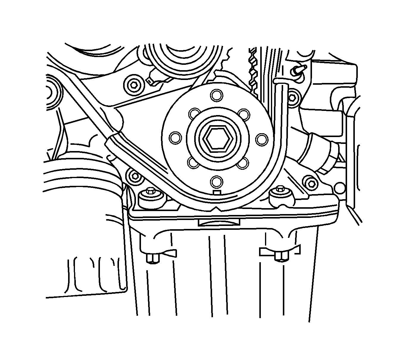
- Remove the crankshaft pulley bolts.
- Remove the crankshaft pulley.
- Remove the front timing belt cover bolts.
- Remove the front timing belt cover.
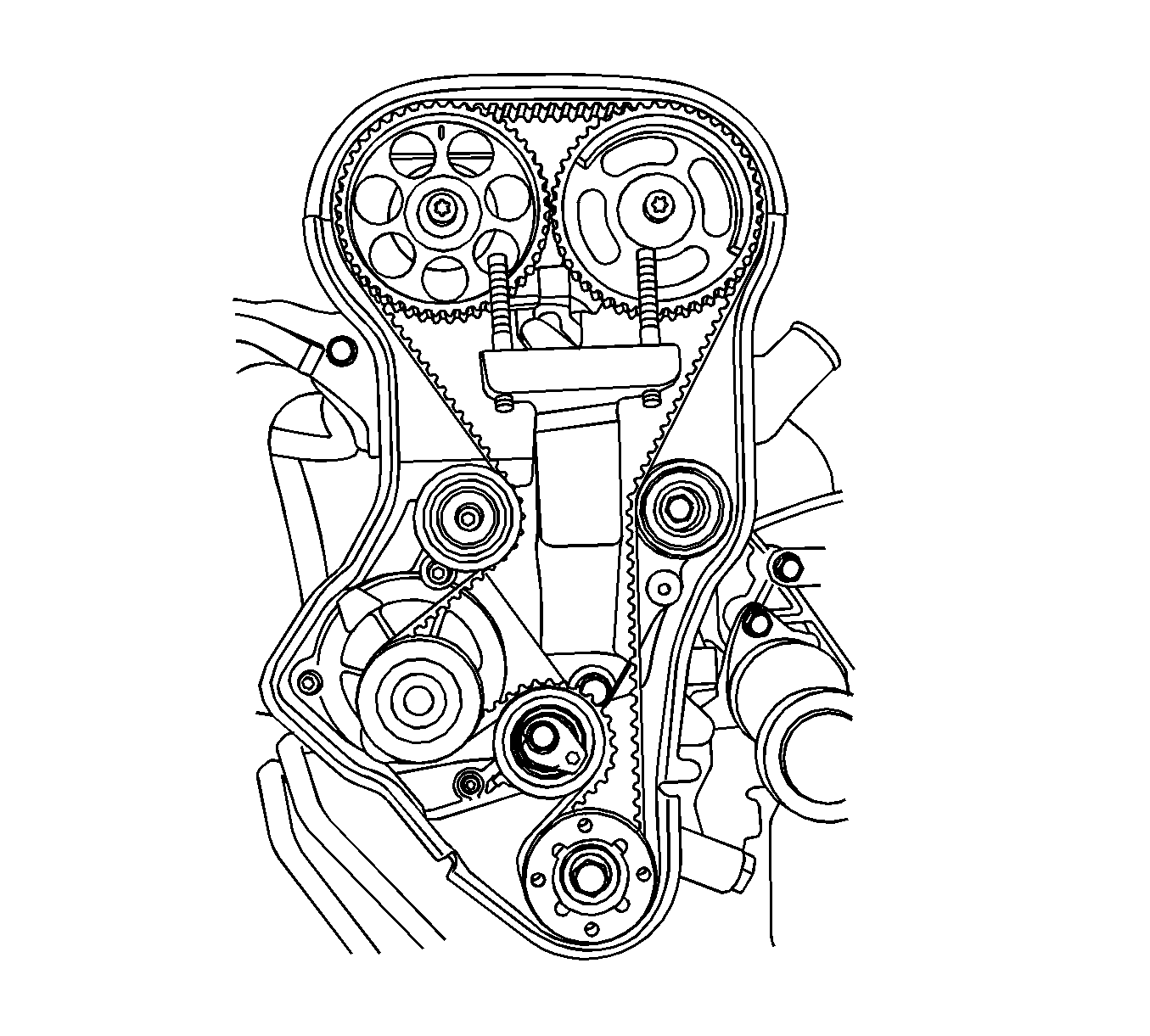
- Loosen the timing belt automatic tensioner bolt.
- Rotate the timing belt automatic tensioner hex-key clockwise to release the tension.
- Remove the timing belt idler pulley bolt and nut.
- Remove the timing belt idler pulleys.
- Remove the timing belt.
- Remove the engine mount adapter support bracket bolts.
- Remove the engine mount adapter support bracket.
- Remove the ignition wires from the spark plugs.
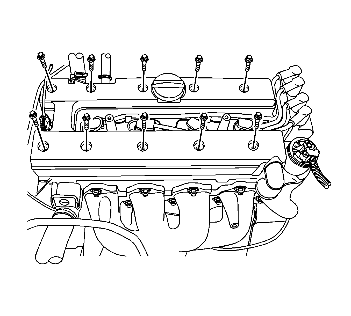
- Remove the cylinder head cover and gasket. Refer to Camshaft Cover Replacement .
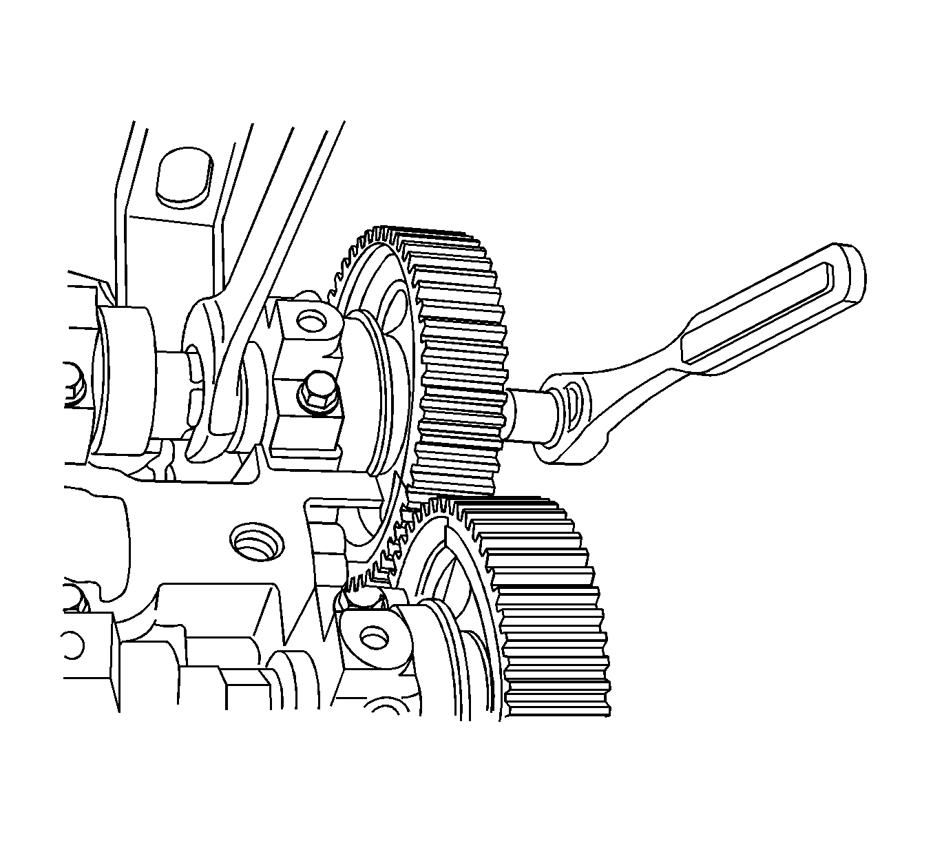
- While holding the intake camshaft firmly in place, remove the intake camshaft gear bolt.
- Remove the intake camshaft gear.
- While holding the exhaust camshaft firmly in place, remove the exhaust camshaft gear bolt.
- Remove the exhaust camshaft gear.
- Remove the crankshaft gear.
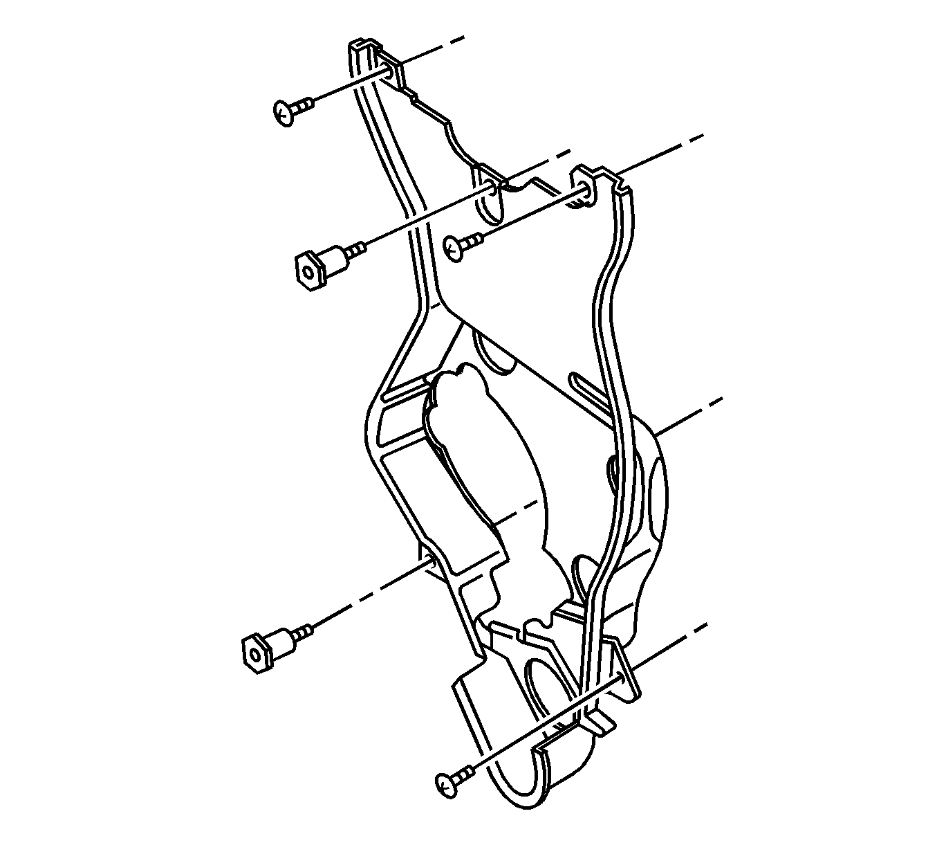
- Remove the rear timing belt cover bolts and the cover.
- Rotate the engine on the OTC 1726 .
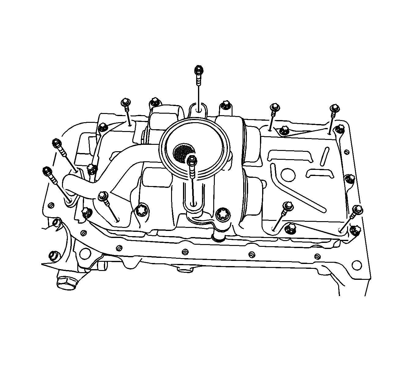
- Remove the oil pan retaining bolts.
- Remove the oil pan.
- Remove the oil suction pipe bolts.
- Remove the oil suction pipe with O-ring.
- Remove the oil pan scraper bolts.
- Remove the oil pan scrapers.
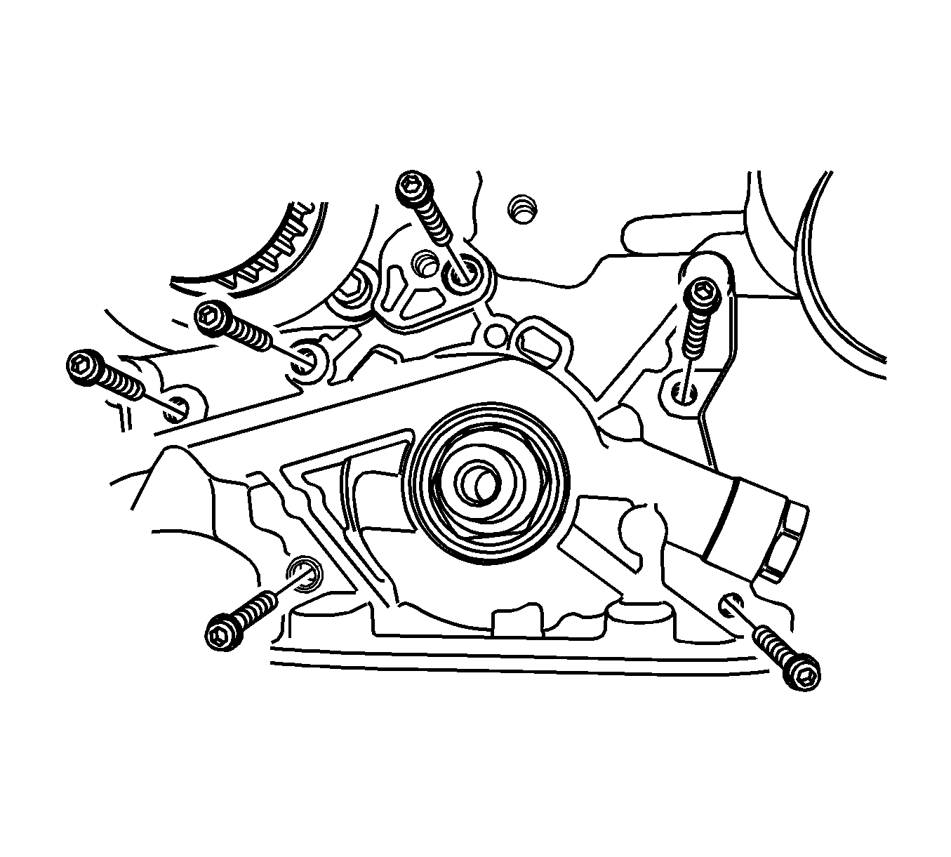
- Remove the oil pump retaining bolts.
- Remove the oil pump.
- Mark the order of the connecting rod bearing caps for installation.
- Remove the connecting rod bearing cap bolts for all of the pistons.
- Remove the connecting rod bearing caps and the lower connecting rod bearings.
- Mark the order of the crankshaft bearing caps for installation.
- Remove the crankshaft bearing cap bolts.
- Remove the crankshaft bearing caps and the lower crankshaft bearings.
- Remove the crankshaft.
- Clean the parts if needed.
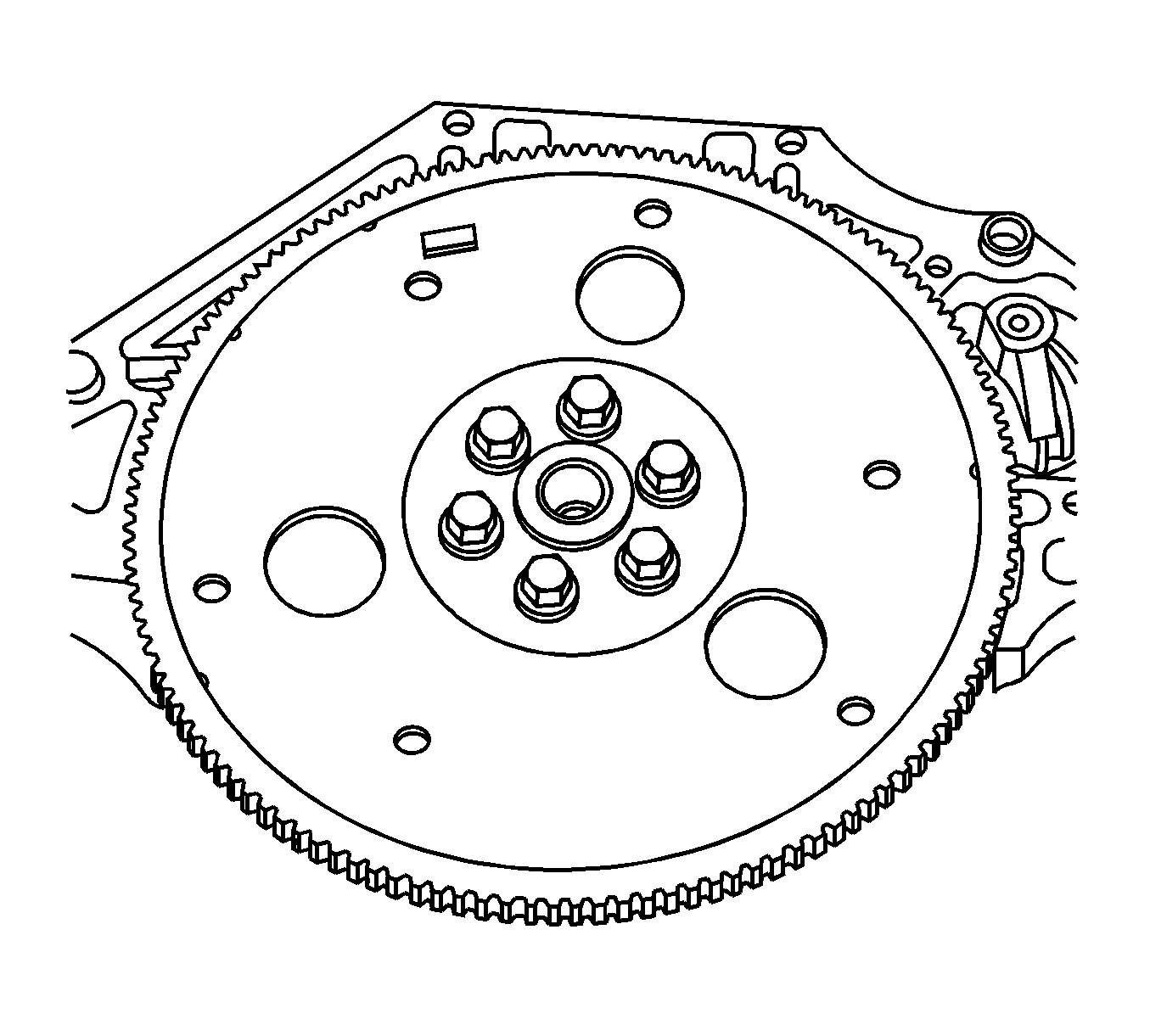
Important: Take extreme care to prevent any scratches, nicks or damage to the camshafts.
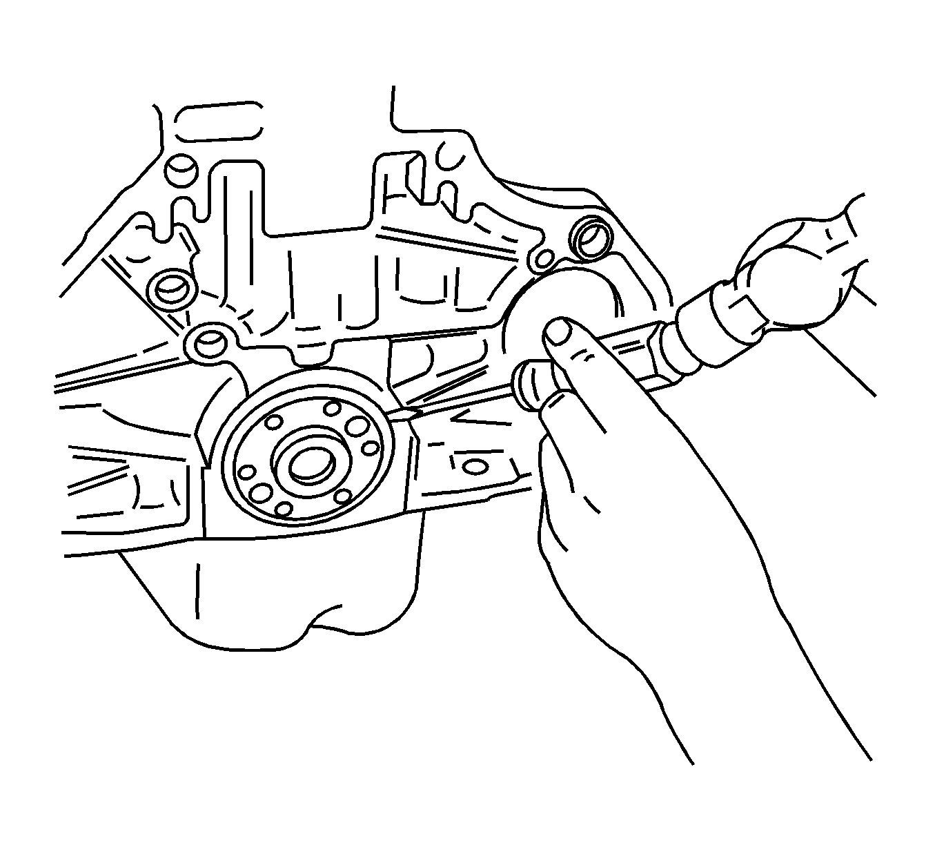
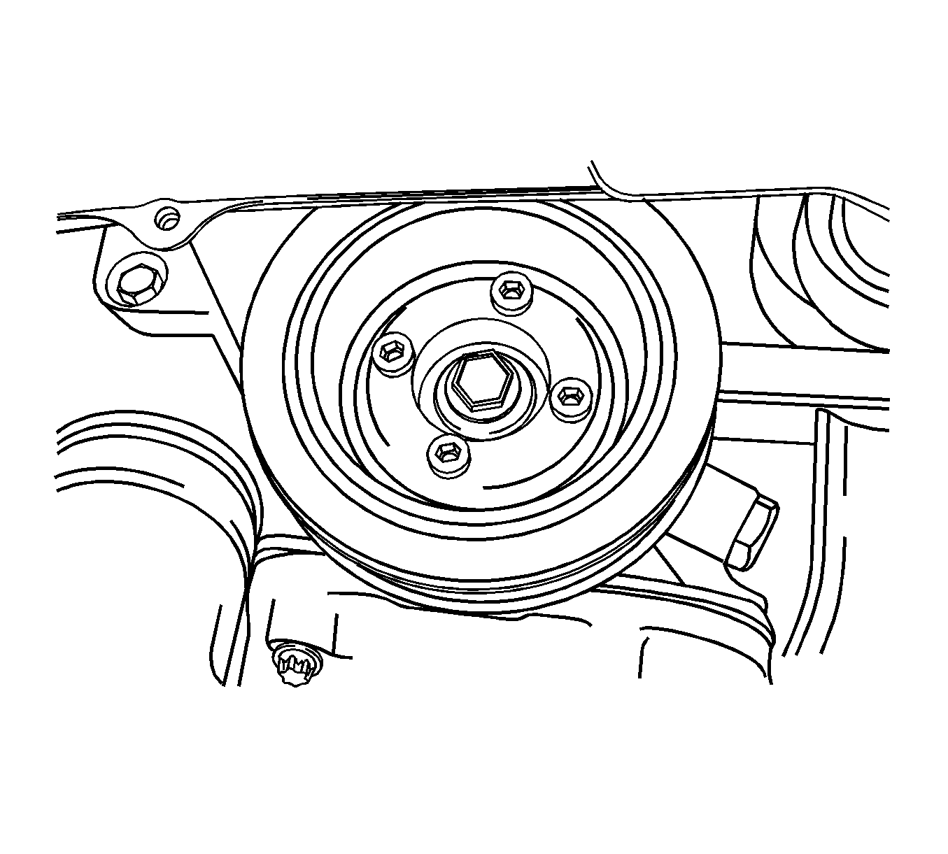
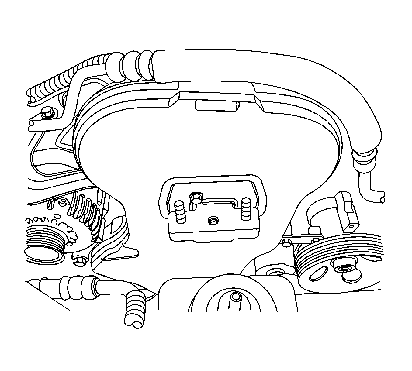
Important: Take extreme care to prevent any scratches, nicks or damage to the camshafts.
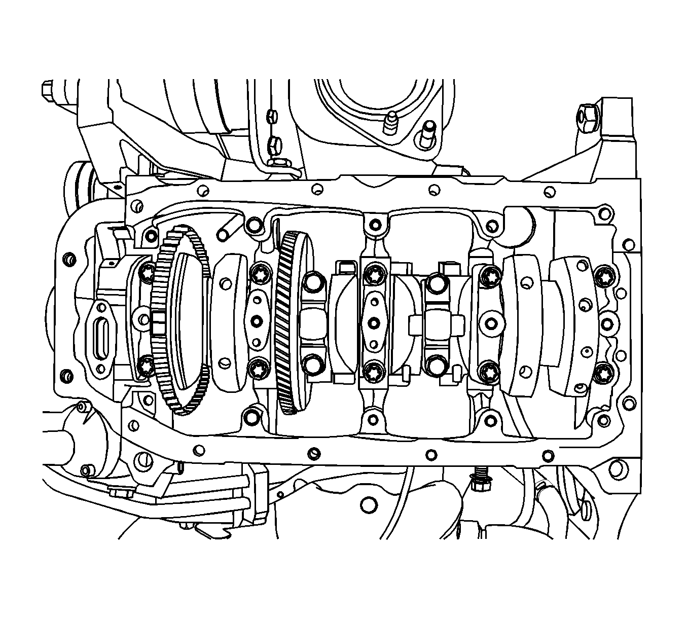

Assembly Procedure
- Coat the crankshaft bearings with engine oil.
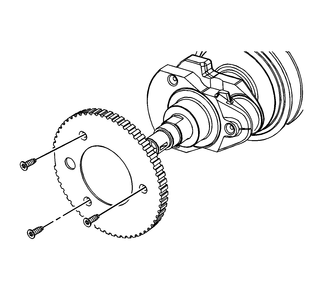
- If replacing the crankshaft, transfer the reluctor wheel to the new crankshaft.
- Install the crankshaft.
- Install the lower crankshaft bearings in the bearing caps.
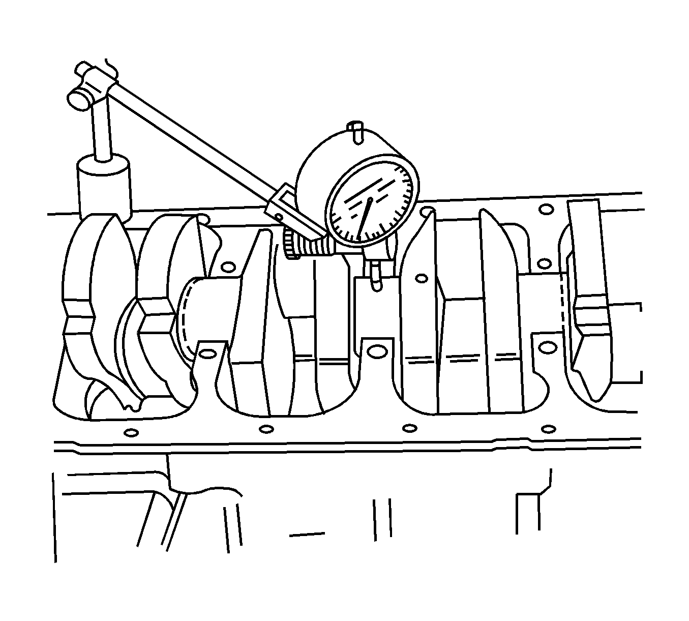
- Inspect the crankshaft end play with the crankshaft bearings installed.
- Check for permissible crankshaft end play. Refer to Engine Mechanical Specifications .
- With the crankshaft mounted on the front and rear crankshaft bearings, check the middle crankshaft journal for permissible out-of-round (runout). Refer to Engine Mechanical Specifications .
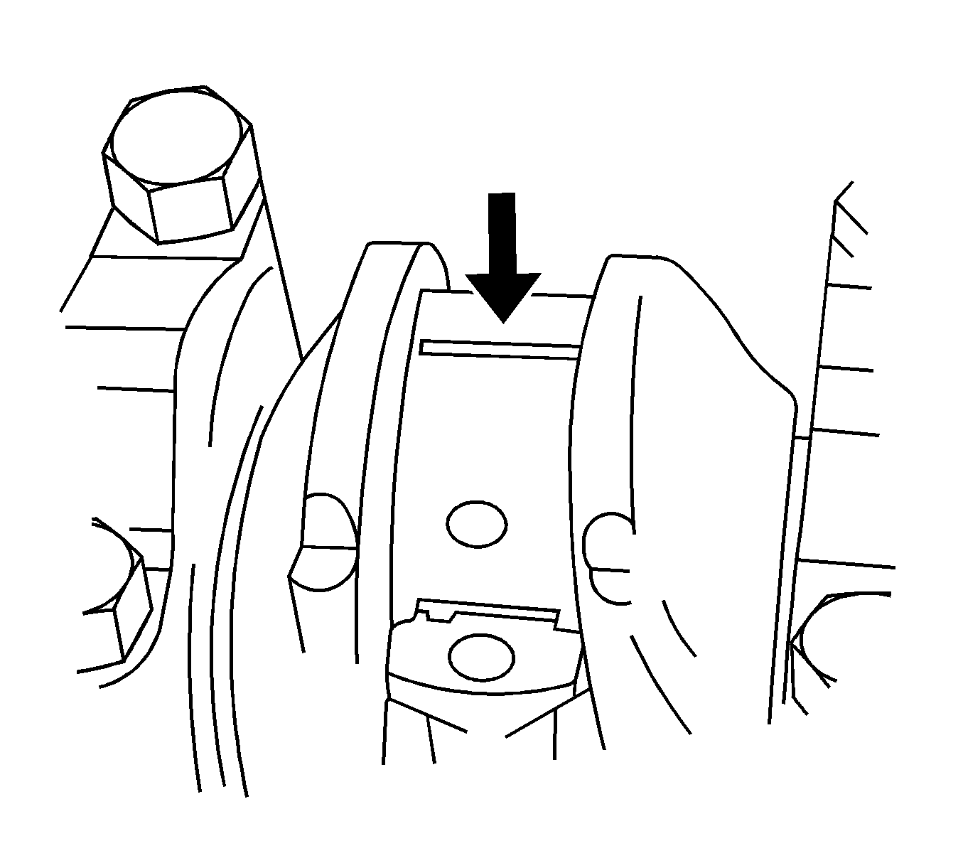
- Inspect all crankshaft bearing clearances using a commercially available plastic gaging (ductile plastic threads).
- Cut the plastic gaging threads to the length of the bearing width. Lay them axially between the crankshaft journals and the crankshaft bearings.
- Install the crankshaft bearing caps and the bolts.
- Remove the crankshaft bearing cap bolts and the caps.
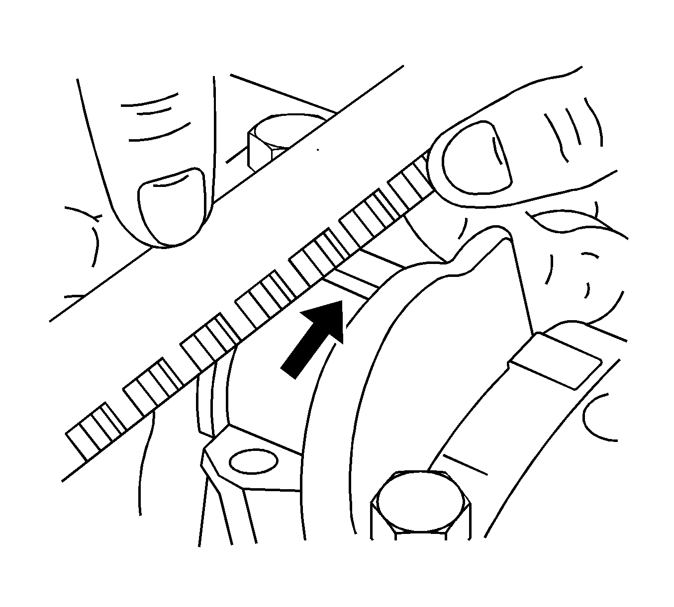
- Measure the width of the flattened plastic thread of the plastic gaging using a ruler. (Plastic gauging is available for different tolerance ranges.)
- Inspect the bearing clearance for permissible tolerance ranges. Refer to Engine Mechanical Specifications .
- Apply a bead of adhesive sealing compound to the grooves of the crankshaft bearing caps.
- Install the crankshaft bearing caps to the engine block.
- Tighten the crankshaft bearing caps using new bolts.
- Inspect all of the connecting rod bearing clearances using a commercially available plastic gaging (ductile plastic threads).
- Cut the plastic gaging threads to the length of the connecting rod bearing width. Lay them axially between the connecting rod journals and the connecting rod bearings.
- Install the connecting rod bearing caps.
- Remove the connecting rod bearing caps.
- Measure the width of the flattened plastic thread of the plastic gaging using a ruler. (Plastic gaging is available for different tolerance ranges.)
- Inspect the bearing clearance for permissible tolerance ranges. Refer to Engine Mechanical Specifications .
- Install the connecting rod bearing caps to the connecting rods.
- Tighten the connecting rod bearing caps using new bolts.
- Install the oil pump.
- Install the oil pump retaining bolts.
- Install the crankshaft balancer unit assembly.
- Install the crankshaft balancer unit assembly retaining bolts.
- Install the oil pan scrapers.
- Install the oil pan scraper retaining bolts.
- Install the oil suction pipe with the new O-ring.
- Install the oil suction pipe retaining bolts.
- Coat the sealant on the oil pan mating surface.
- Install the oil pan.
- Install the oil pan retaining bolts.
- Rotate the engine OTC 1726 .
- Install the rear timing belt cover.
- Install the rear timing belt cover bolts.
- Install the crankshaft gear and the bolt.
- Install the engine mount adapter support bracket and the bolts.
- Install the timing belt idler pulley.
- Install the timing belt idler pulley bolt and nut.
- Install the intake camshaft gear.
- Install the intake camshaft gear bolt while holding the intake camshaft firmly in place.
- Install the exhaust camshaft gear.
- Install the exhaust camshaft gear bolt while holding the exhaust camshaft firmly in place.
- Install the timing belt automatic tensioner.
- Install the timing belt. Refer to Timing Belt Replacement .
- Adjust the timing belt tension. Refer to Timing Belt Inspection and Adjustment .
- Apply a small amount of gasket sealant to the corners of the front camshaft caps and to the top of the rear cylinder head cover to cylinder head seal.
- Install the cylinder head cover and the cylinder head cover gasket. Refer to Camshaft Cover Replacement .
- Connect the ignition wires to the spark plugs.
- Connect the breather hose and PCV hose to the cylinder head cover.
- Install the front timing belt cover.
- Install the front timing belt cover bolts.
- Install the hoist to the engine support bracket and lift the engine assembly far enough to take the weight off OTC 1726 .
- Remove the engine from the OTC 1726 .
- Install a new crankshaft rear oil seal using J 36972 .
- Install the flywheel or flexible plate.
- Install the flywheel or flexible plate bolts.
- Install the engine. Refer to Engine Replacement .
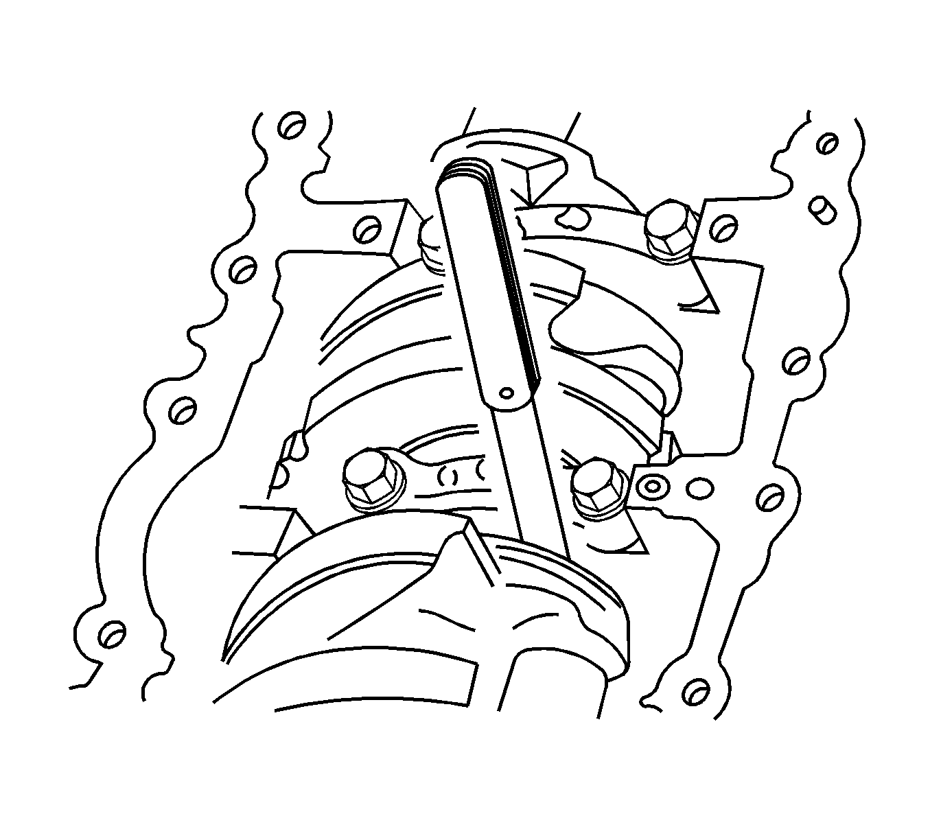
Important: Grease the crankshaft journals and lubricate the crankshaft bearings slightly so that the plastic gaging thread does not tear when the crankshaft bearing caps are removed.
Notice: Refer to Fastener Notice in the Preface section.
Tighten
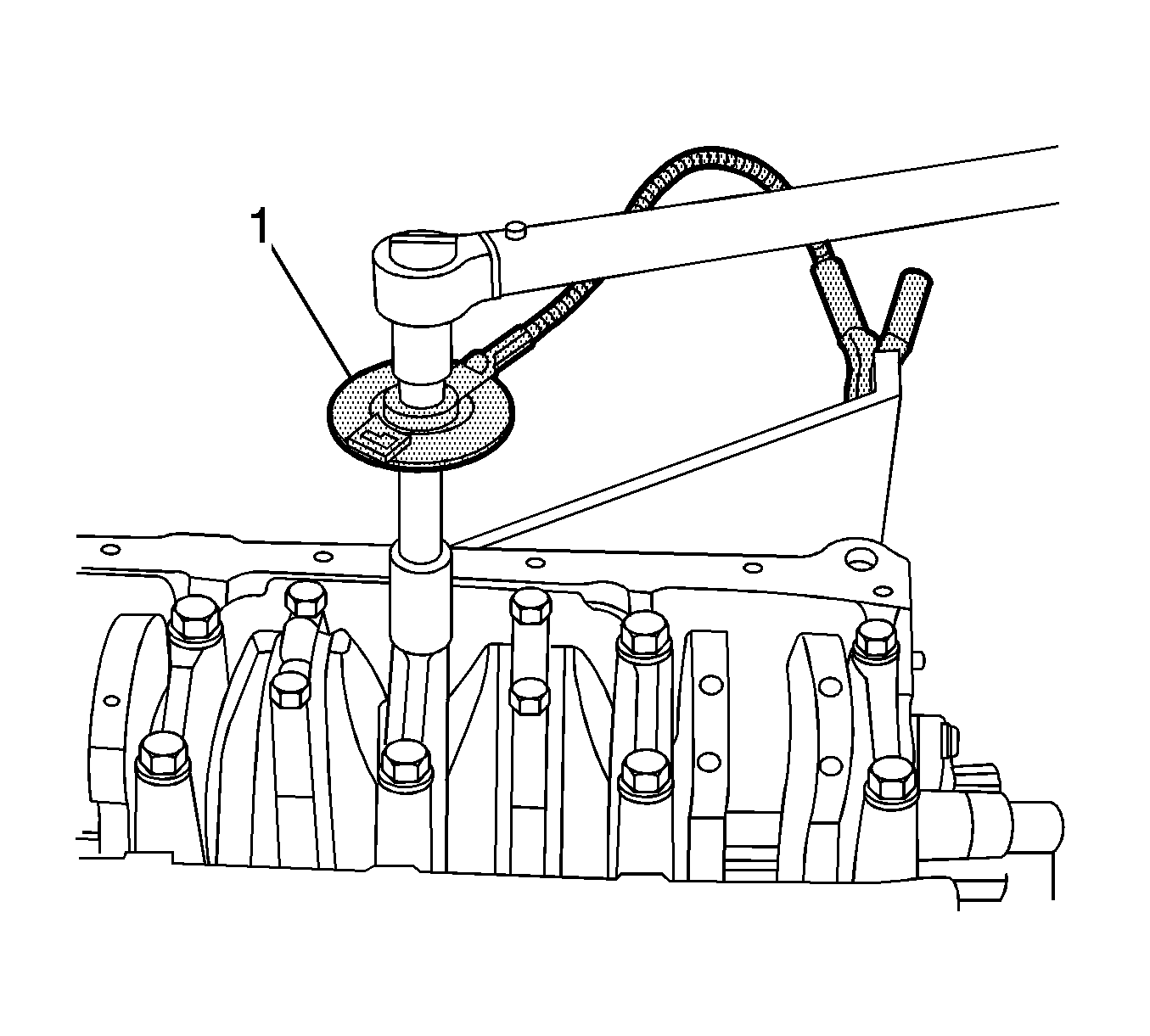
Tighten the crankshaft bearing cap bolts to 50 N·m (37 lb ft) plus 45 degrees and 15 degrees
Important: Grease the connecting rod journals and lubricate the connecting rod bearings slightly so that the plastic gaging thread does not tear when the connecting rod bearing caps are removed.
Tighten
Tighten the crankshaft bearing cap bolts to 50 N·m (37 lb ft) using a torque wrench. Use the
KM-470-B
to tighten the crankshaft bearings another
45 degrees and 15 degrees.

Tighten
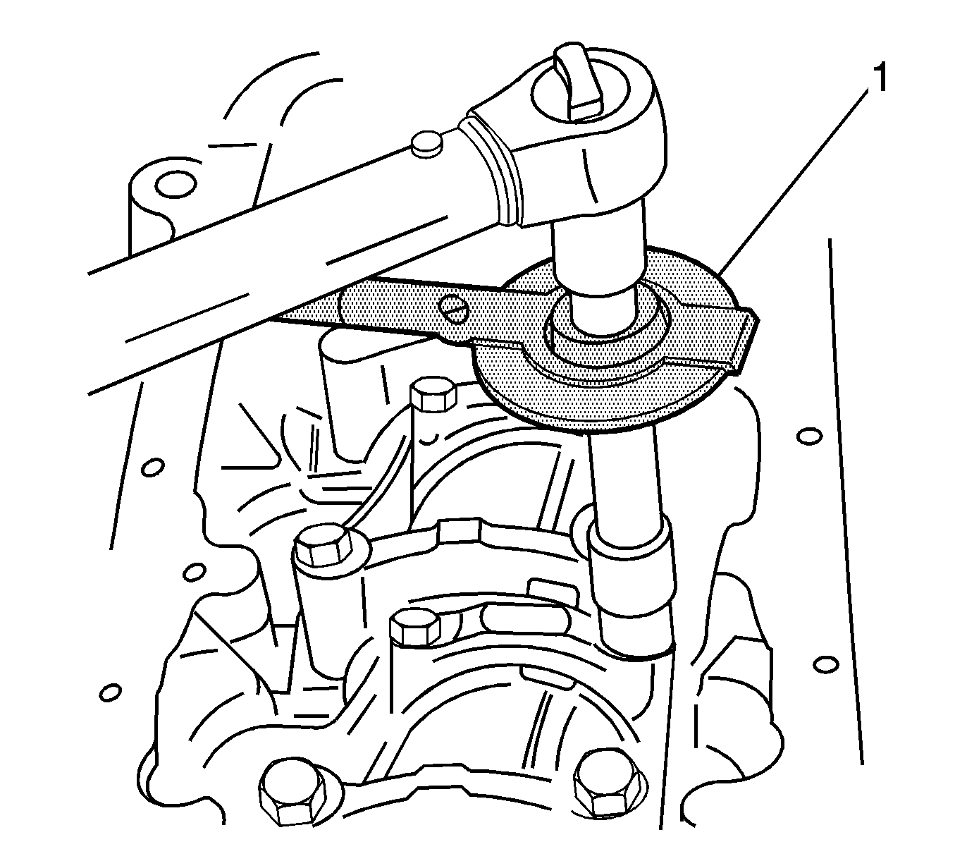
Tighten the connecting rod bearing cap bolts to 35 N·m (26 lb ft) using a torque wrench. Use the
KM-470-B
to tighten the connecting rod bearing
cap bolts another 45 degrees plus 15 degrees.


Tighten
Tighten the oil pump retaining bolts to 10 N·m (89 lb in).
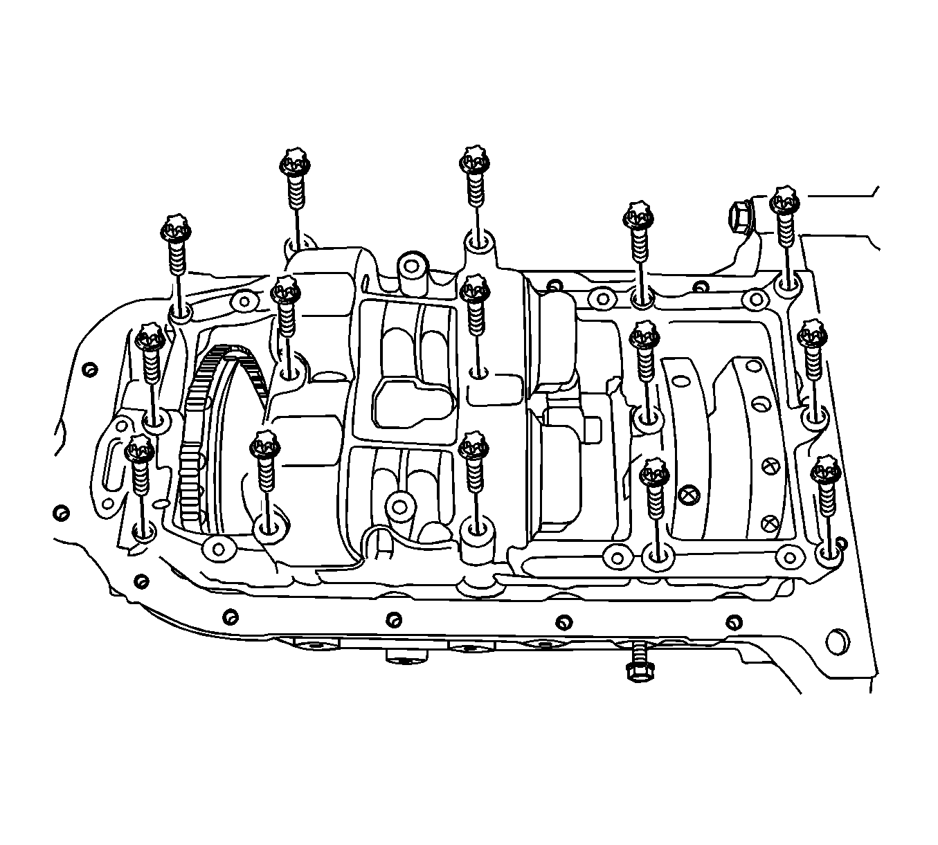
Tighten
Tighten the crankshaft balancer unit assembly retaining bolts to 20 N·m (15 lb ft) and turn the bolts another 45 degrees using
KM-470-B
.
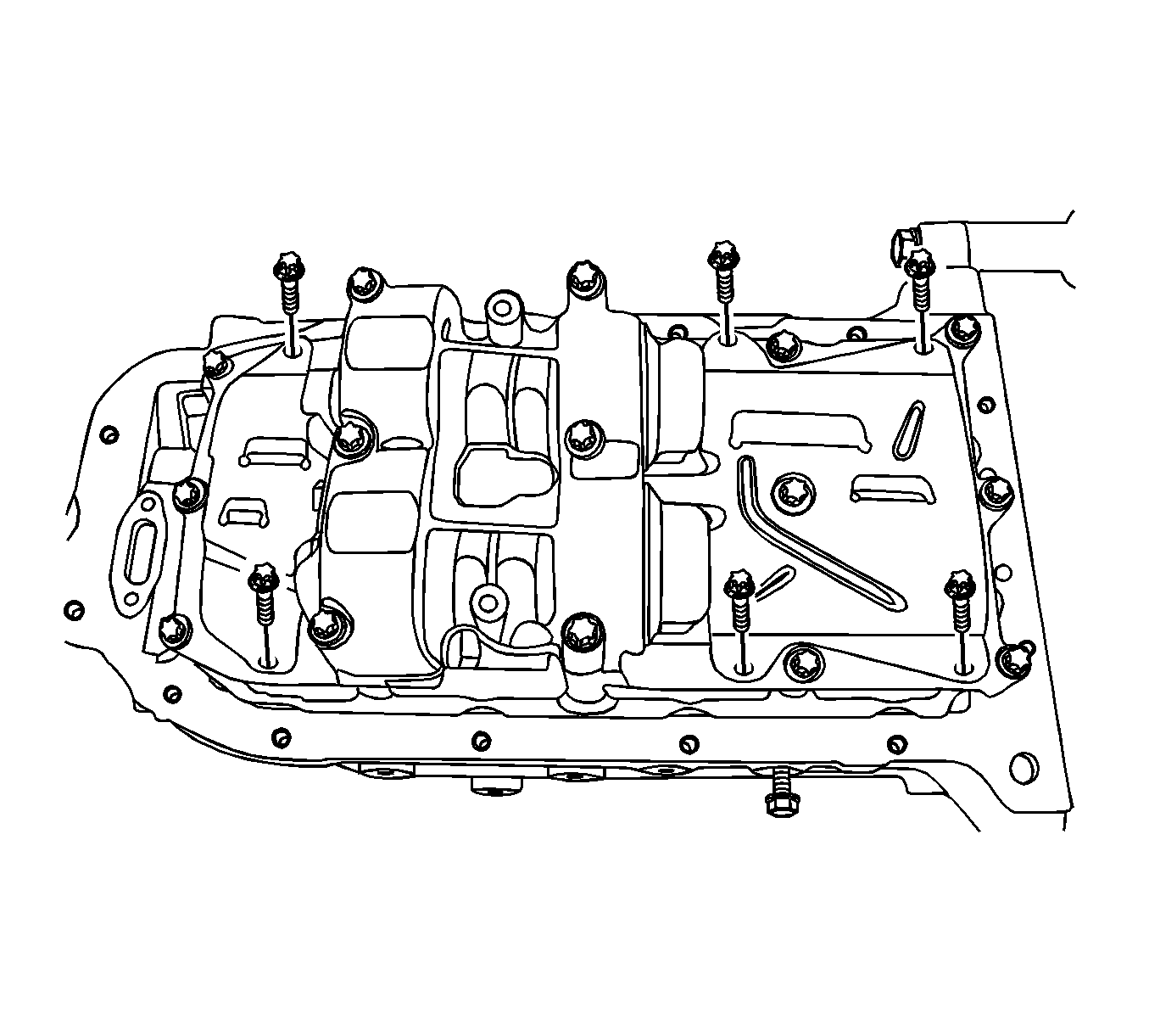
Tighten
Tighten the oil pan scraper retaining bolts to 8 N·m (71 lb in).
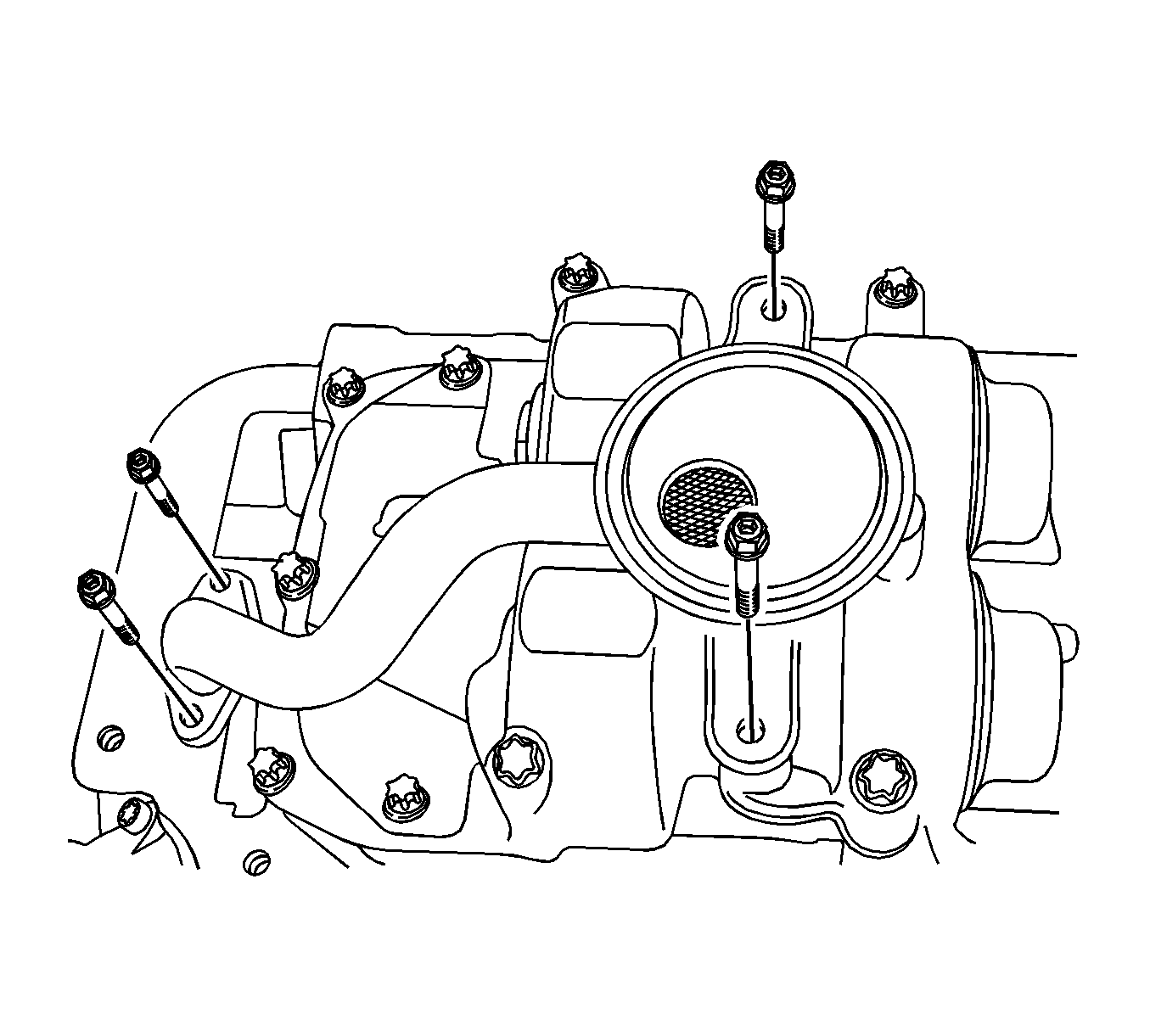
Tighten
Tighten the oil pan scraper retaining bolts to 8 N·m (71 lb in).
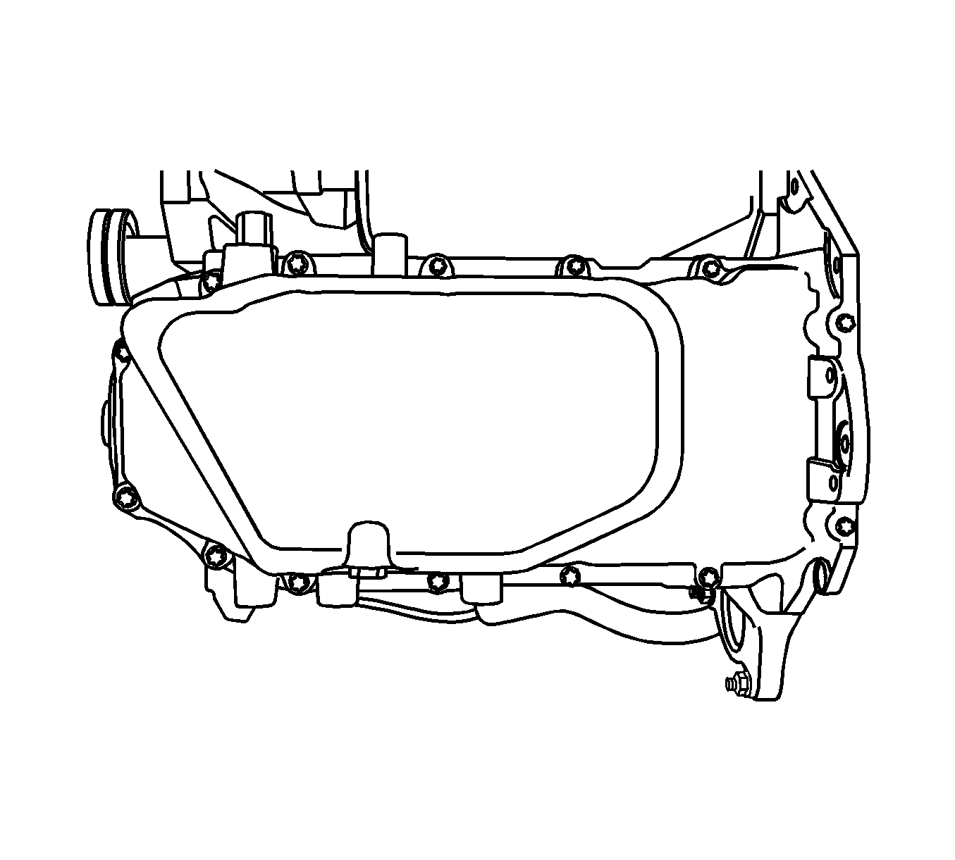
Tighten
Tighten the oil pan retaining bolts to 10 N·m (89 lb in).

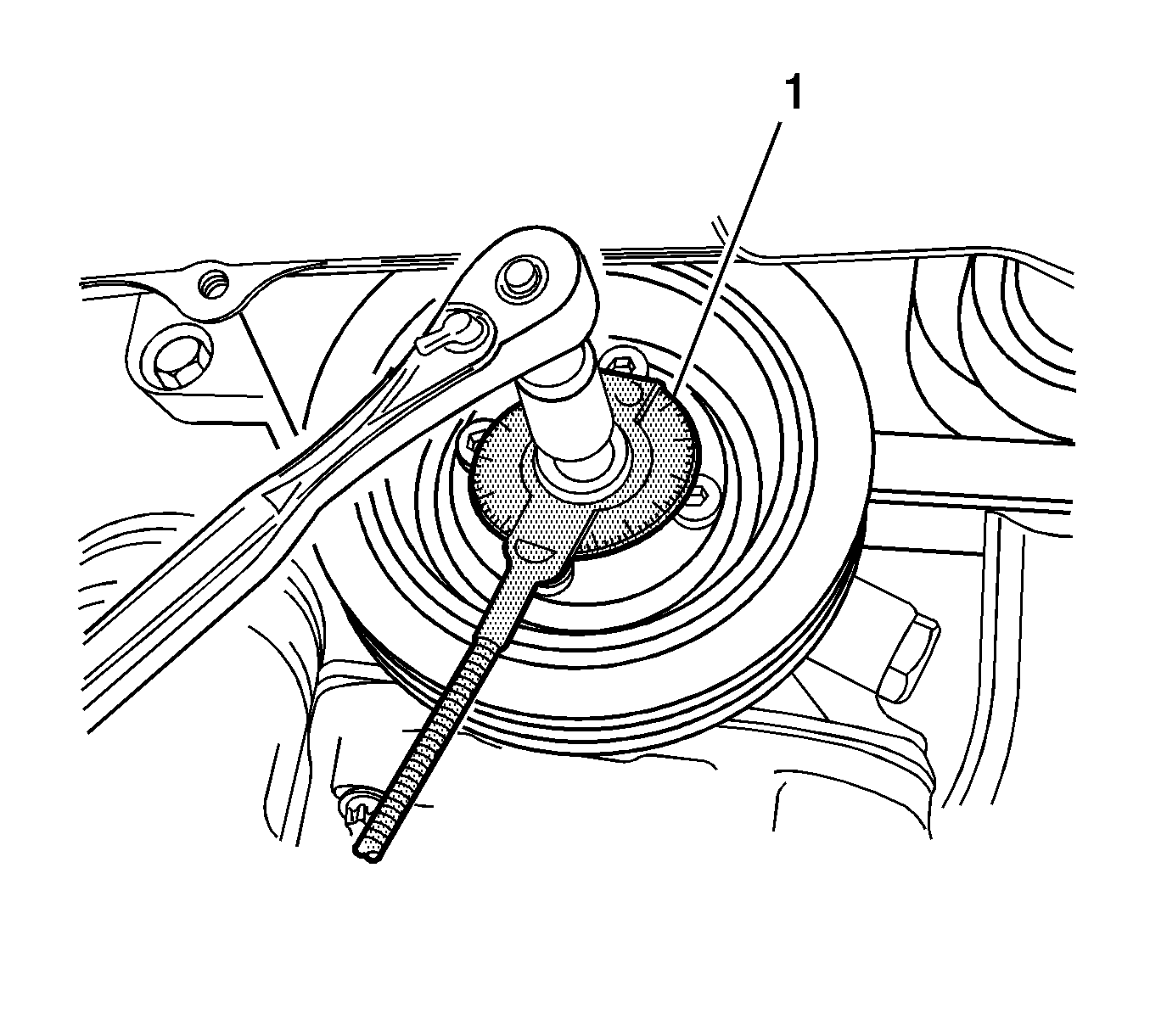
Tighten
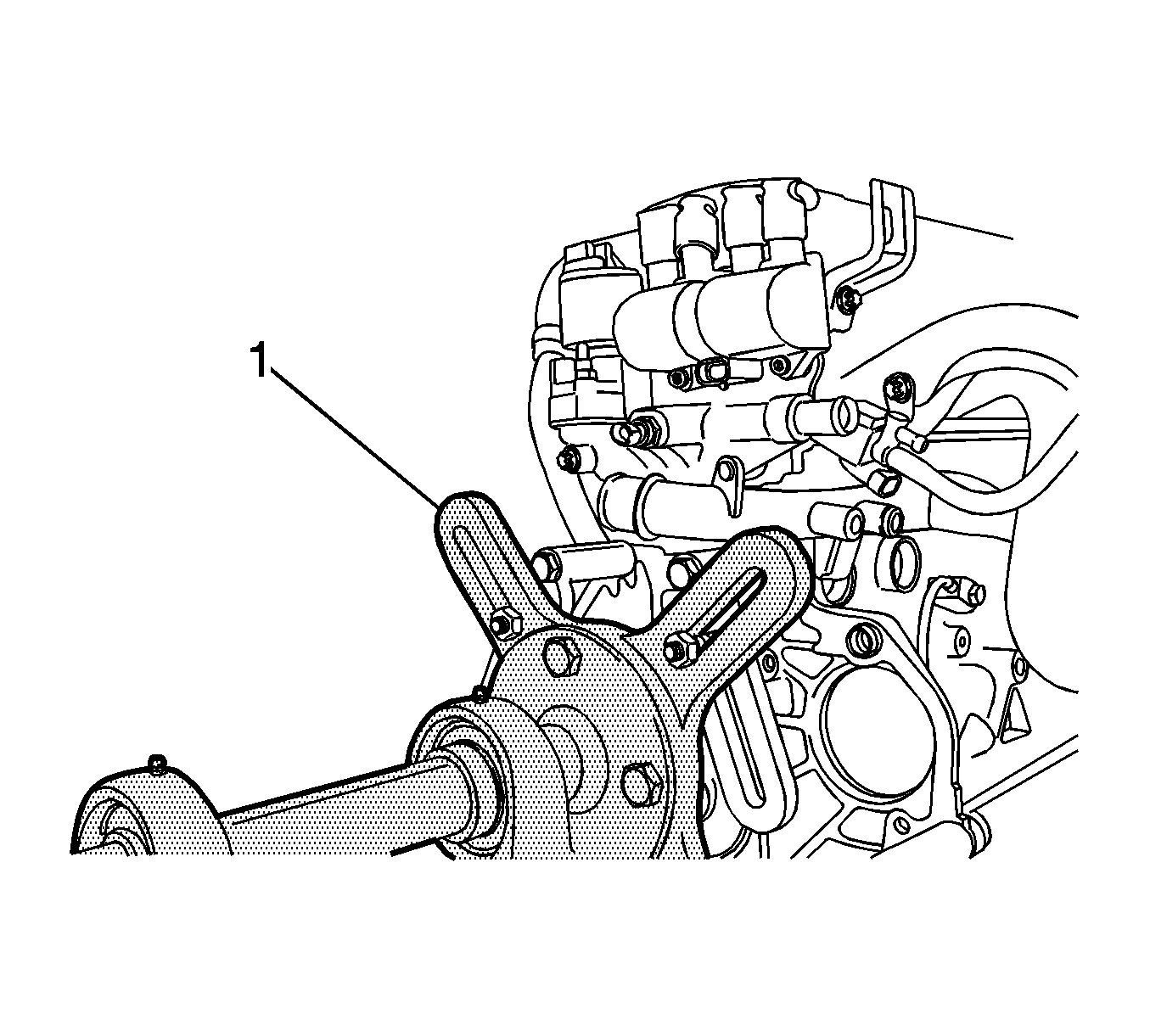
Tighten the crankshaft gear bolt to 135 N·m (100 lb ft) plus 30 degrees plus 10 degrees using
KM-470-B
(1).
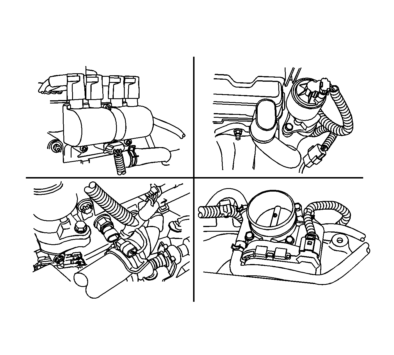
Tighten
Tighten the engine mount adapter support bracket retaining bolts to 45 N·m (33 lb ft).
Tighten
Tighten the timing belt idler pulley bolt and nut to 25 N·m (18 lb ft).
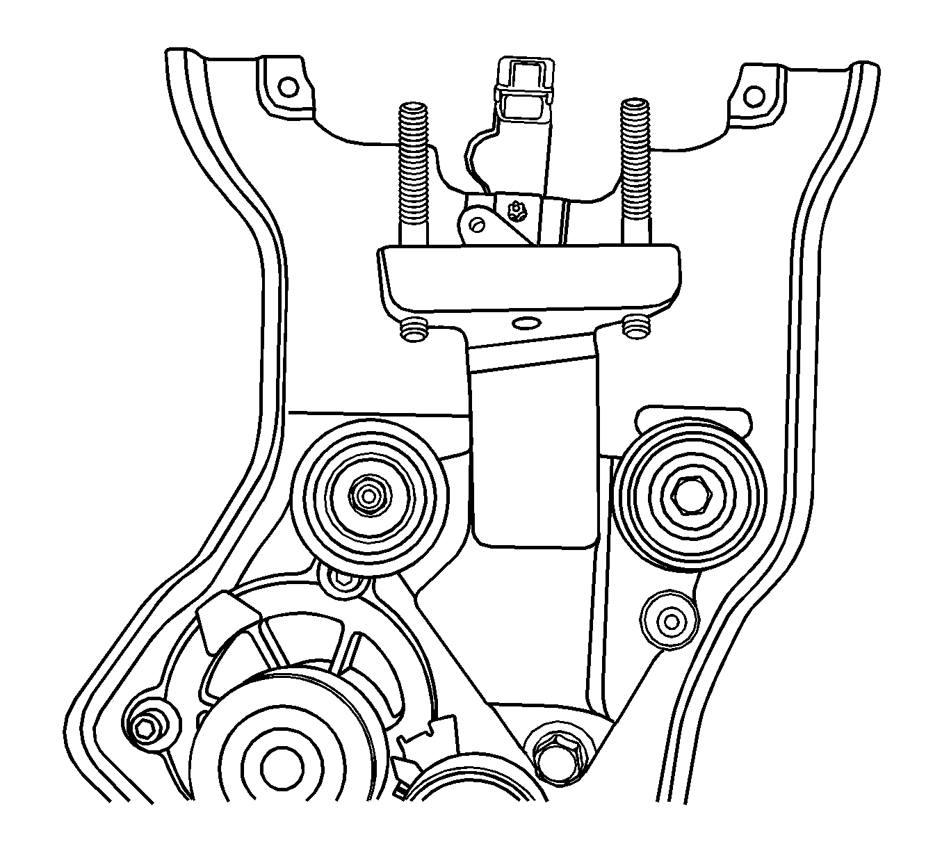
Important: Take extreme care to prevent any scratches, nicks or damage to the camshafts.
Tighten
Tighten the intake camshaft gear bolt to 50 N·m (37 lb ft) plus 60 degrees and 15 degrees using
KM-470-B
.
Tighten
Tighten the exhaust camshaft gear bolts to 50 N·m (37 lb ft) plus 60 degrees and 15 degrees using
KM-470-B
.

Tighten
Tighten the timing belt automatic tensioner bolts to 25 N·m (18 lb ft).

Tighten
Tighten the cylinder head cover bolts to 8 N·m (71 lb in).

Tighten
Tighten the front timing belt cover bolts to 6 N·m (53 lb in).
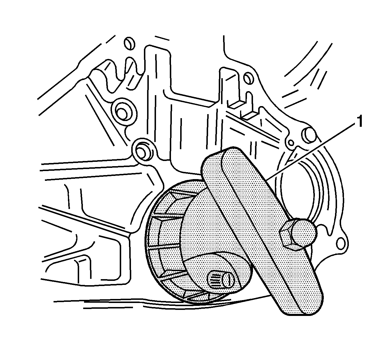
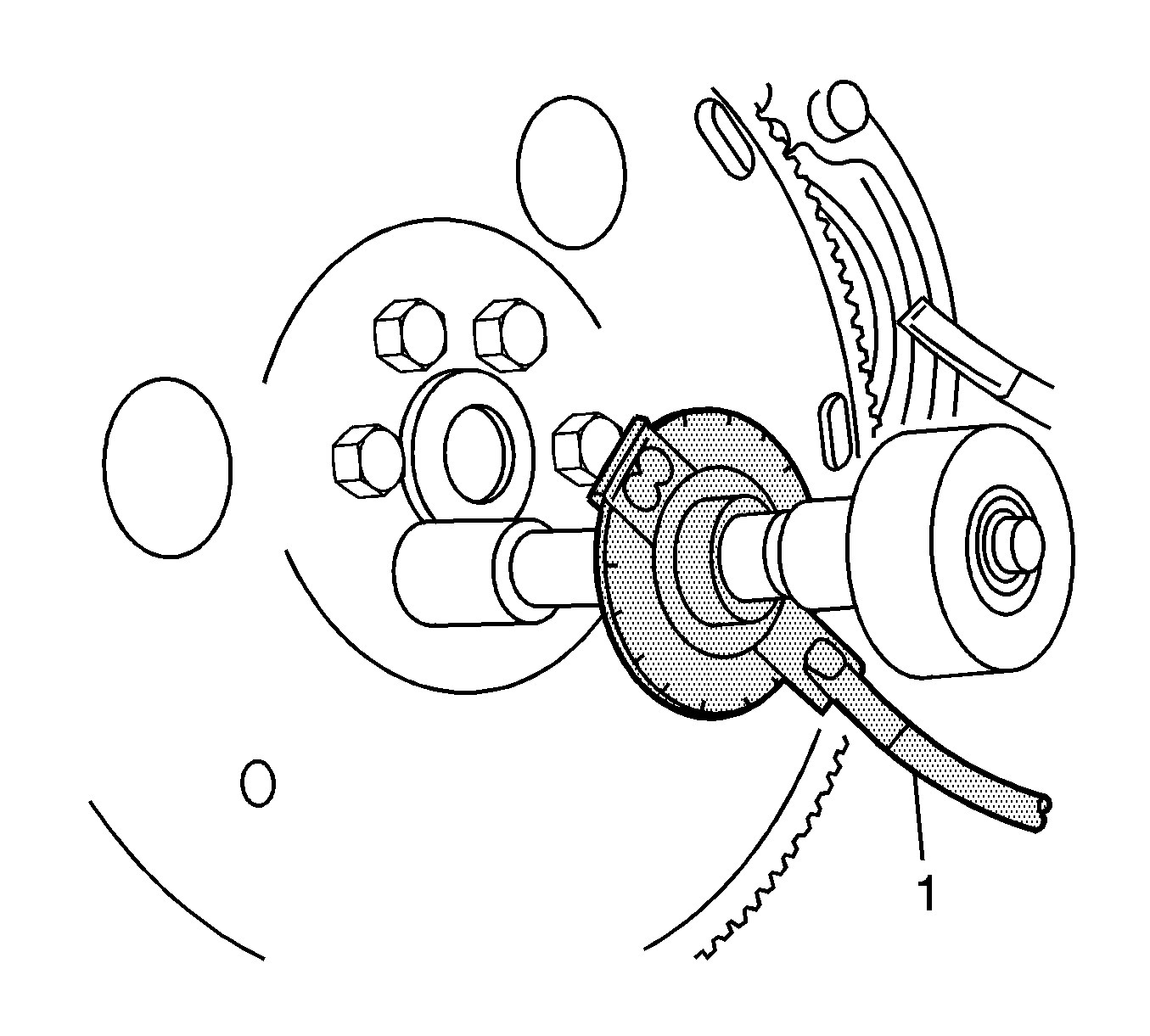
Tighten
Tighten the flywheel bolts to 65 N·m (48 lb ft) . Use
KM-470-B
(1) to tighten the flywheel bolts another 30 degrees plus 15 degrees
. For the automatic transaxle, tighten the flexible plate bolts to 45 N·m (33 lb ft) .
