Special Tools
KM-470-B
Angular Torque Gage
Removal Procedure
Caution: Refer to Battery Disconnect Caution in the Preface section.
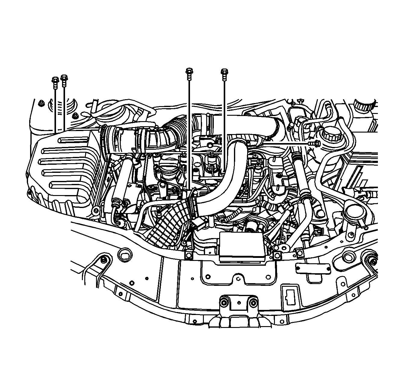
- Disconnect the negative battery cable.
- Remove the engine cover. Refer to
Engine Cover Replacement
.
- Remove the charge air system hoses and ducts. Refer to
Charge Air Cooler Inlet Pipe and Outlet Pipe Replacement
.
- Remove the accessory belt. Refer to
Drive Belt Replacement
.
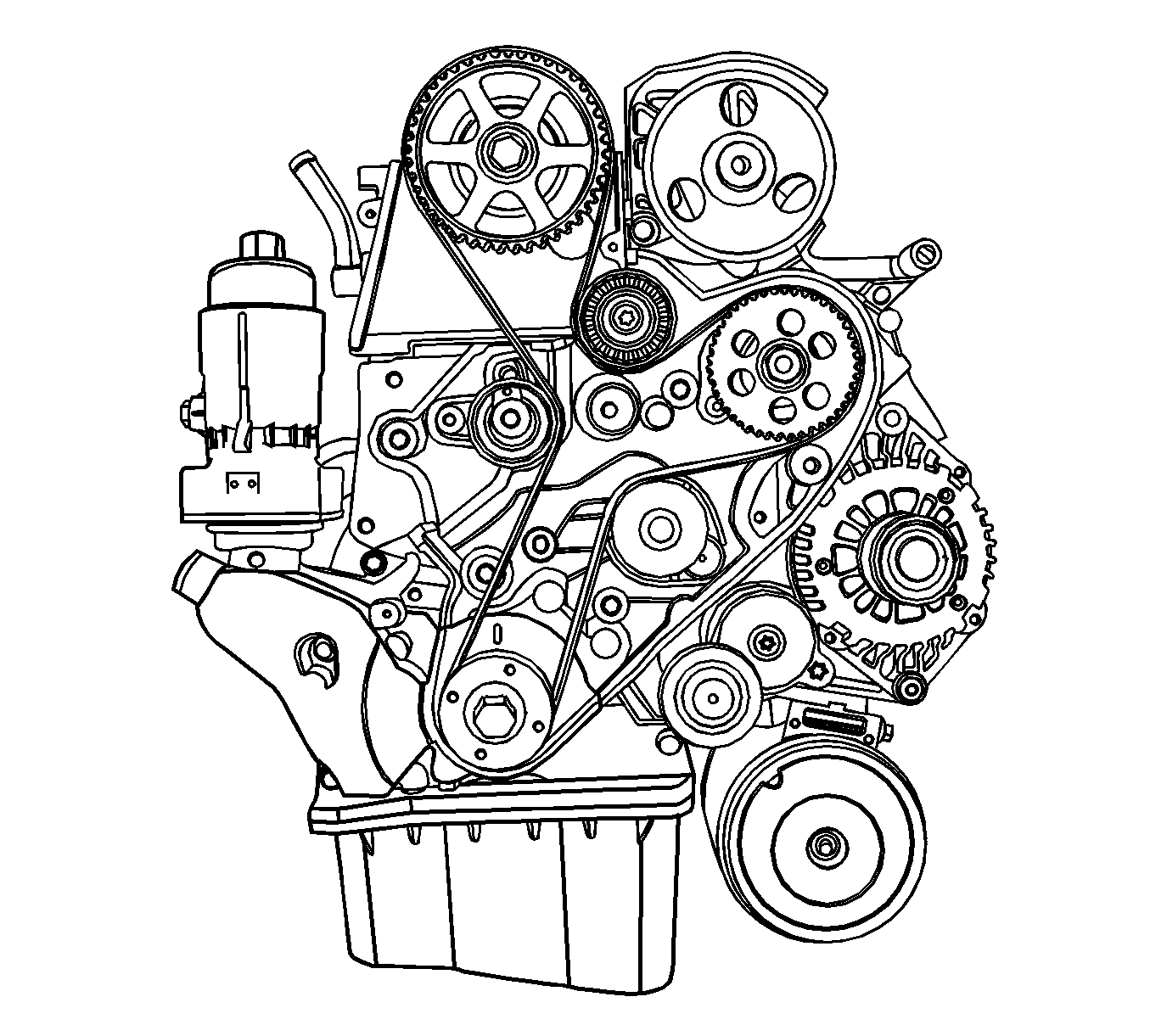
- Remove the valve rocker arm cover. Refer to
Valve Rocker Arm Cover Replacement
.
- Remove the timing belt. Refer to
Timing Belt Replacement
.
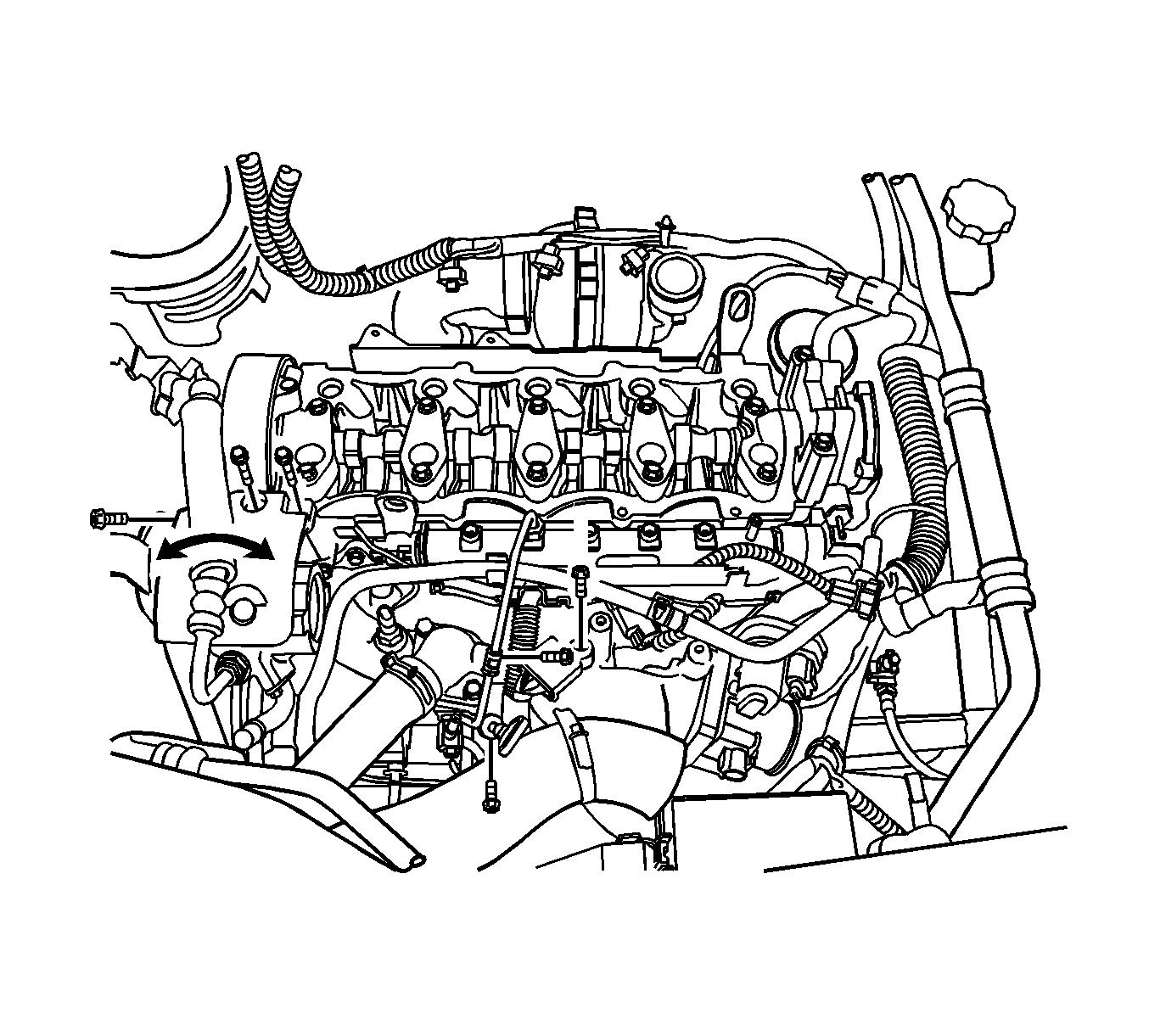
- Remove the fuel pipe-to-common rail between common rail and fuel injection pump. Refer to
Fuel Injector Fuel Feed Pipe Replacement
.
- Remove the power steering pump fastener and pull it left side.
- Remove the engine wiring splice pack tightening bolt.
- Remove the oil level indicator tube.
- Remove the radiator upper hose from the thermostat housing.
- Remove the engine wiring connectors.
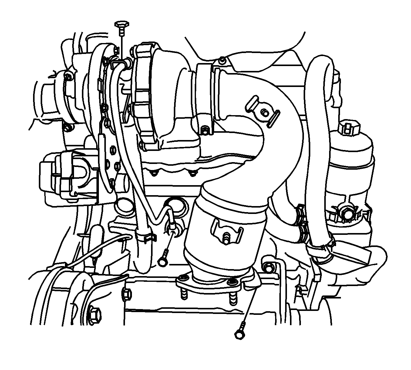
- Remove the turbocharger wheel bearing oil inlet pipe.
- Remove the turbocharger wheel bearing oil outlet hose.
- Remove the pre-catalyst tightening clamp from the turbocharger.
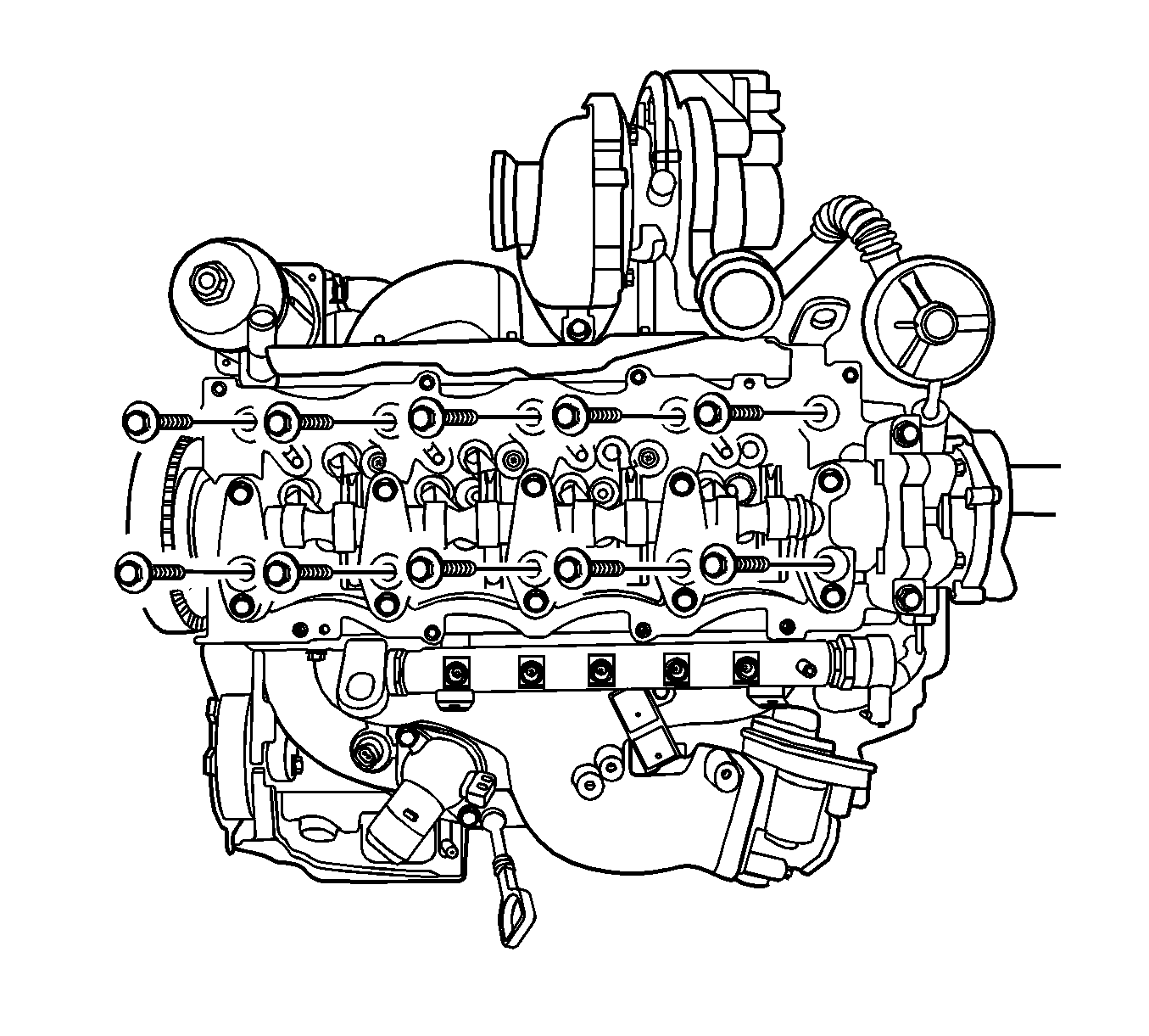
- Remove the cylinder head bolts.
- Remove the cylinder head assembly with the gasket.
- Remove the intake manifold and exhaust manifold from cylinder head assembly.
Cleaning Procedure
- Clean the cylinder head surface.
- Clean the engine block surface.
- Clean the cylinder head bolts.
- Clean the engine block bolt holes.
Gasket Selection Procedure
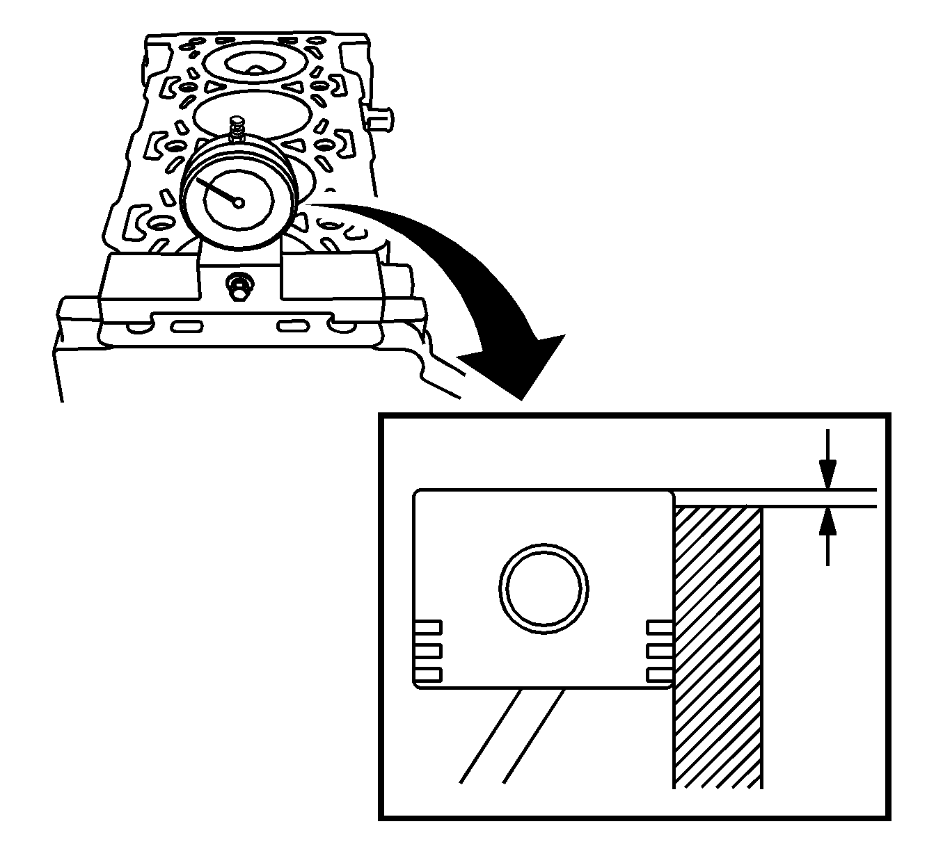
- Align the TDC of the piston.
- Clean the cylinder block sealing surface and piston.
- Measure the piston projection thickness using by dial gage.
- Repeat the measuring process on the other cylinders and average the measured piston projection values.
- Choose the cylinder head gasket specifications.
Specification
| • | Piston Protrusion 0.194-0.337 mm |
| • | Piston Protrusion 0.337-0.440 mm |
| • | Piston Protrusion 0.440-0.542 mm |
Installation Procedure

- Install the cylinder head assembly with a new gasket.
Notice: Refer to Fastener Notice in the Preface section.
- Install the cylinder head tightening bolts.
Tighten
Tighten the cylinder head bolts to 65 N·m (47.9 lb ft). Using
KM-470-B
, tighten the cylinder head bolts another 120 degrees plus 120 degrees.

- Install the pre-catalyst tightening clamp to the turbocharger.
- Install the turbocharger wheel bearing oil inlet pipe.
Tighten
Tighten the turbocharger wheel bearing oil inlet pipe bolts to 23 N·m (17 lb ft).

- Install the engine wiring splice pack tightening bolt.
- Install the power steering pump fastener.
- Install the fuel pipe-to-common rail between common rail and fuel injection pump.
- Install the oil level indicator tube.
Tighten
| • | Tighten the engine wiring splice pack tightening bolt to 15 N·m (11.1 lb ft). |
| • | Tighten the power steering pump bolts to 25 N·m (18.4 lb ft). |
| • | Tighten the fuel pipe-to-common rail retaining to 20 N·m (14.8 lb in). |
| • | Tighten the fuel pipe-to-common rail retaining bolt to 10 N·m (88.5 lb in). |
| • | Tighten the oil level indicator tube bolts to 11 N·m (97.4 lb in). |
- Install the timing belt. Refer to
Timing Belt Replacement
.
- Install the valve rocker arm cover. Refer to
Valve Rocker Arm Cover Replacement
.
- Install the accessory belt. Refer to
Drive Belt Replacement
.
- Install the charge air hoses and ducts. Refer to
Charge Air Cooler Inlet Pipe and Outlet Pipe Replacement
.
- Install the engine cover. Refer to
Engine Cover Replacement
.
- Connect the negative battery cable.


