Tools Required
| • | EN-48243 Engine Assembly Remove/Install Pallet |
| • | EN-48244 Engine Assembly Remove/Install Pallet Supporter |
Removal Procedure
- Discharge the air conditioning (A/C) system, if equipped.
- Drain the power steering oil, if equipped.
- Disconnect the negative battery cable.
- Remove the engine cover. Refer to Engine Cover Replacement .
- Remove the charge air system hoses and ducts. Refer to Charge Air Cooler Inlet Pipe and Outlet Pipe Replacement .
- Drain the engine coolant. Refer to Cooling System Draining and Filling .
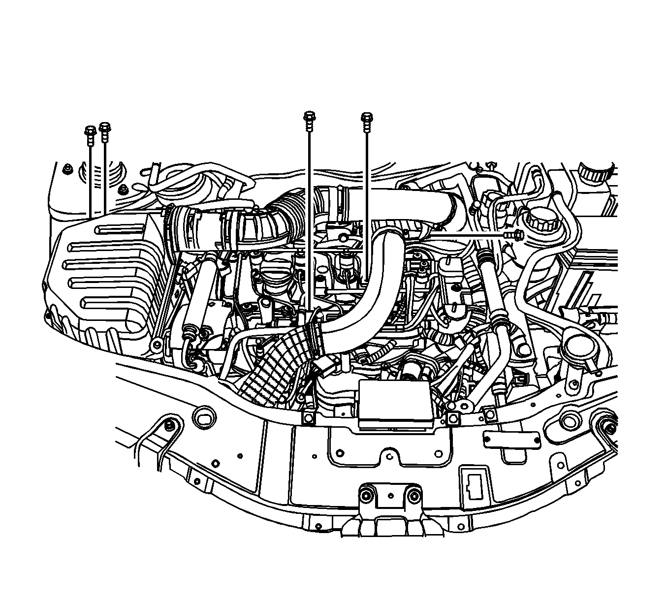
- Disconnect the fuel feeding pipe connector (a).
- Disconnect the coolant hose from the surge tank (b, c).
- Disconnect the fuel return hose from the junction block (d).
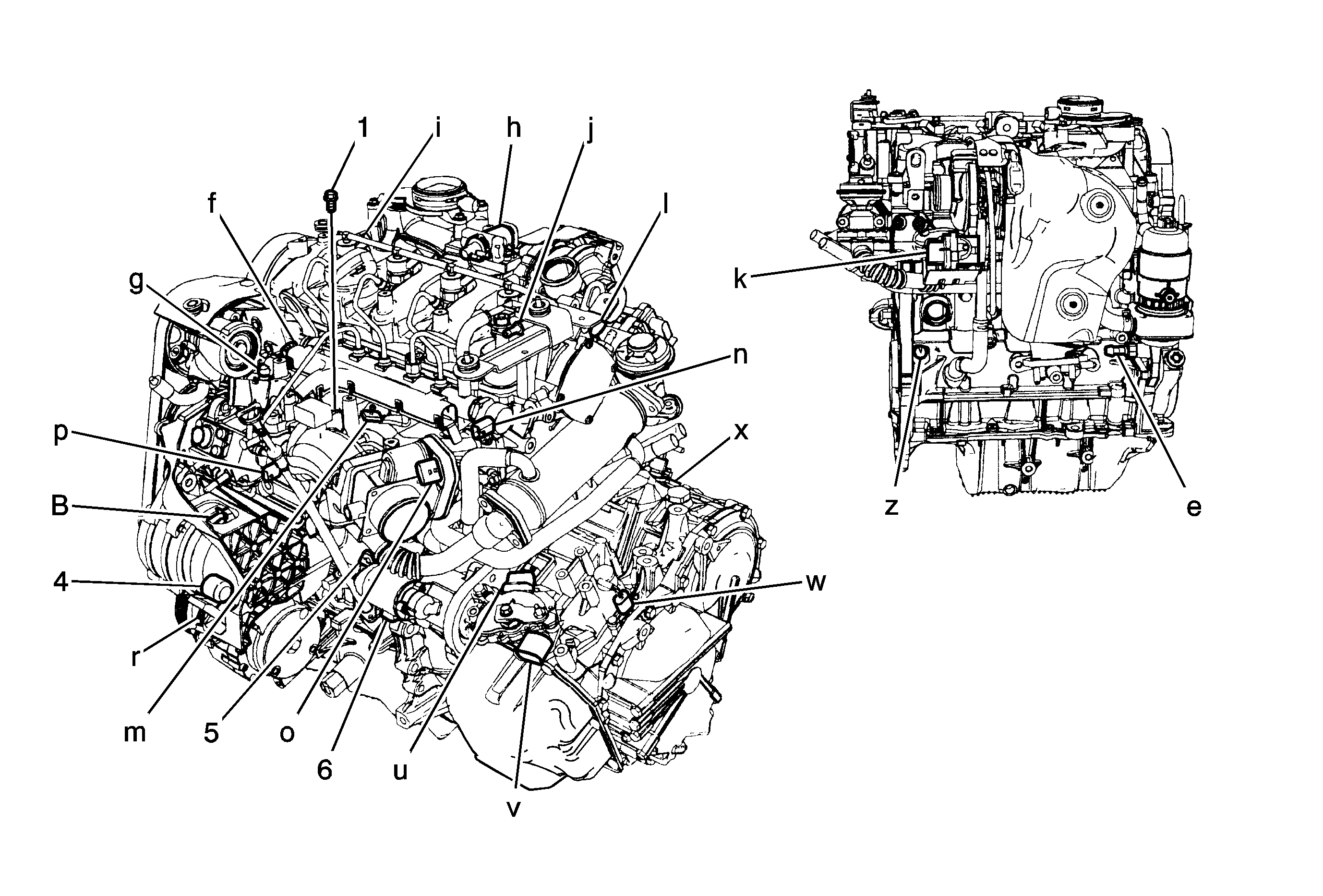
- Disconnect the engine wiring harness as follows:
- Remove the engine hardware and components as follows:
- Remove the surge tank. Refer to Radiator Surge Tank Replacement .
- Remove the power steering pump pipes from the power steering pump.
- Remove the front drive axle shafts. Refer to Front Wheel Drive Shaft Replacement .
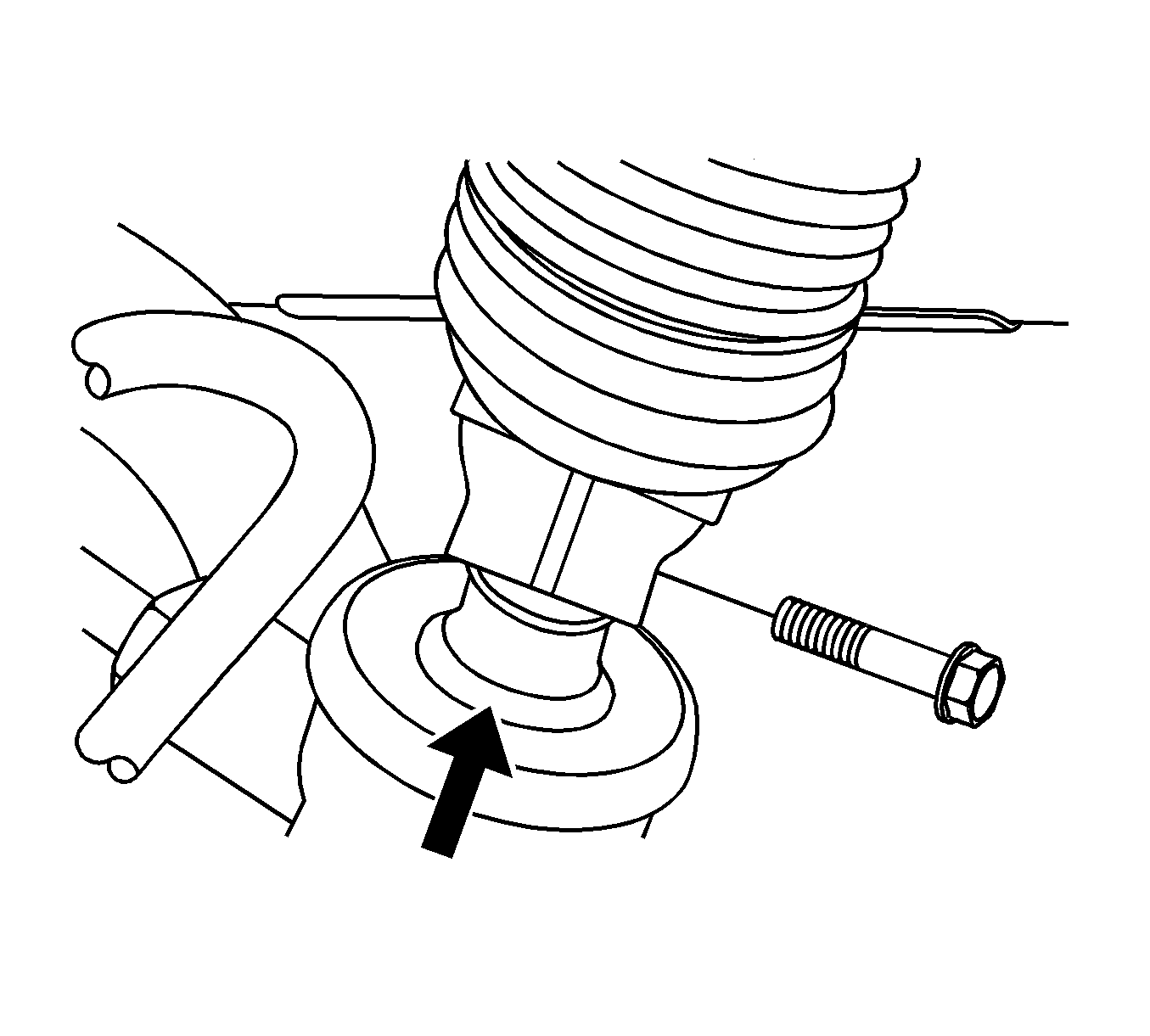
- Remove the steering intermediate shaft lower pinch bolt.
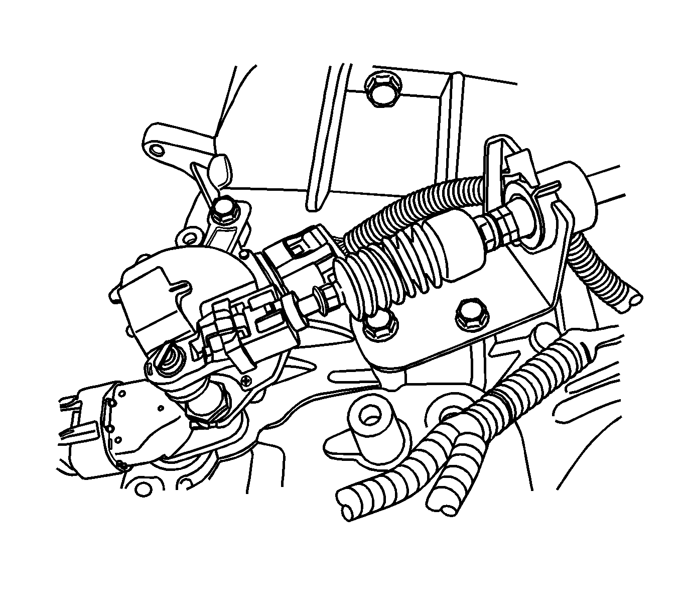
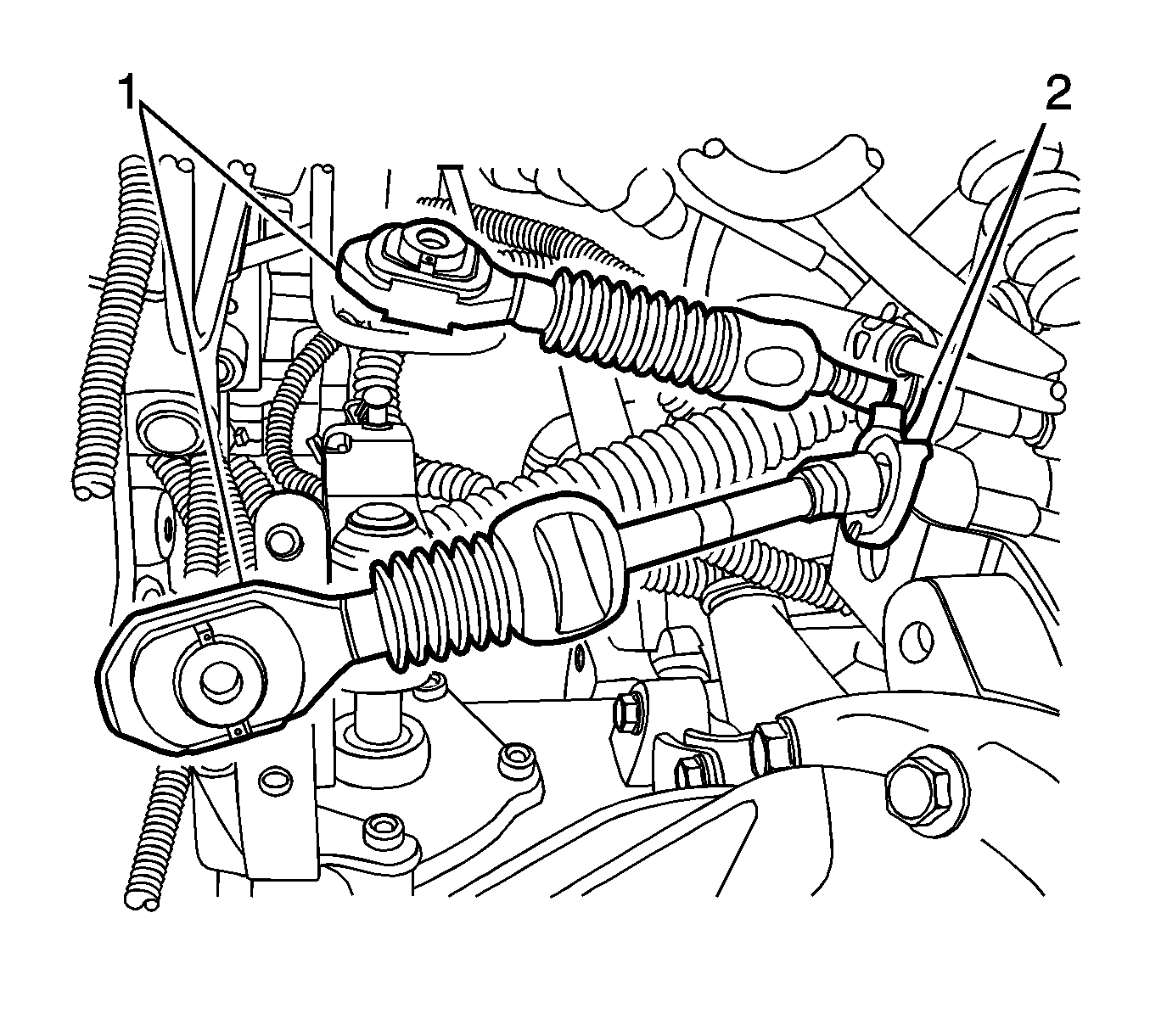
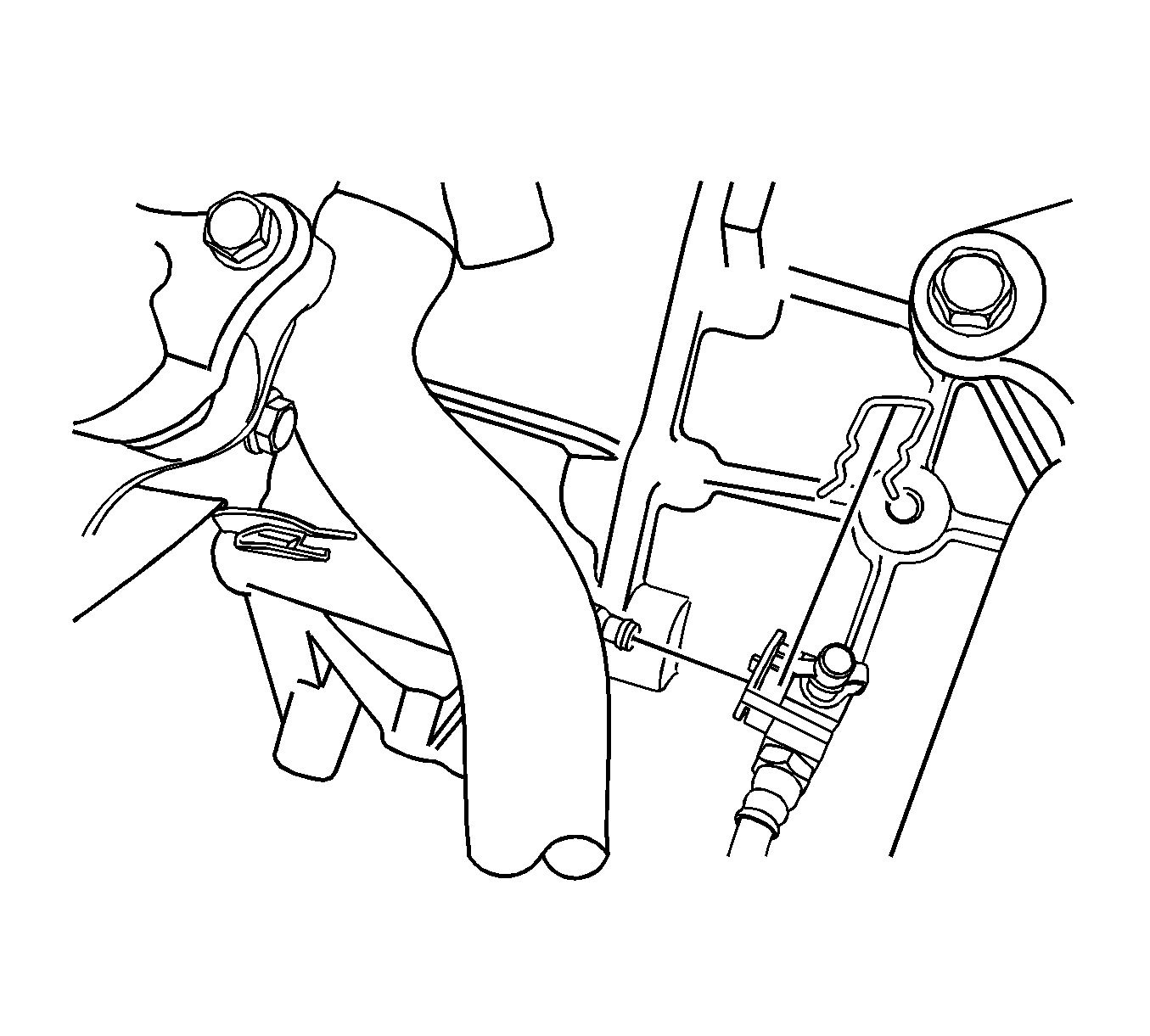
- For automatic transaxle, remove the shift control cable from the automatic transaxle. Refer to Shift Control Cable Replacement .
- For manual transaxle, remove the select cable from the transaxle. Refer to Transmission Control Replacement .
- For automatic transaxle, remove the transaxle oil cooler hoses from the auto-transaxle.
- For manual transaxle, remove the clutch actuator cylinder pipe from the transaxle. Refer to Clutch Concentric Actuator Cylinder Replacement .
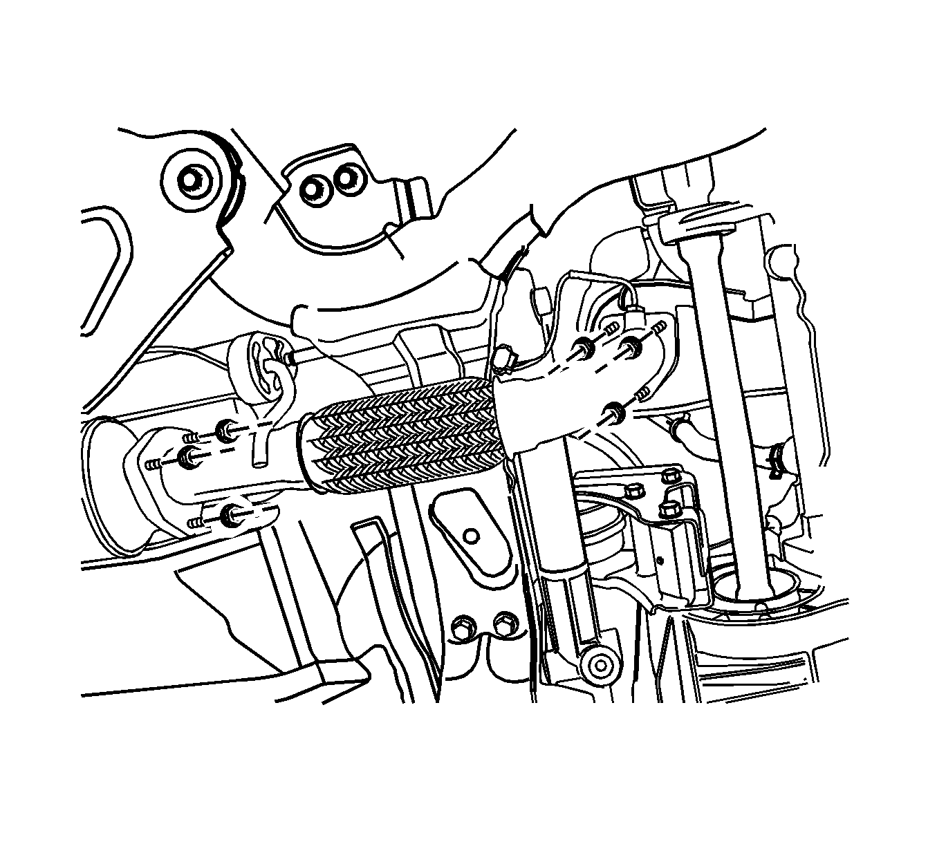
- Remove the front exhaust pipe between the pre-catalyst and the diesel particulate filter pipe.
- Remove the A/C compressor pipe from the compressor.
- Remove the power steering return cooling pipe.
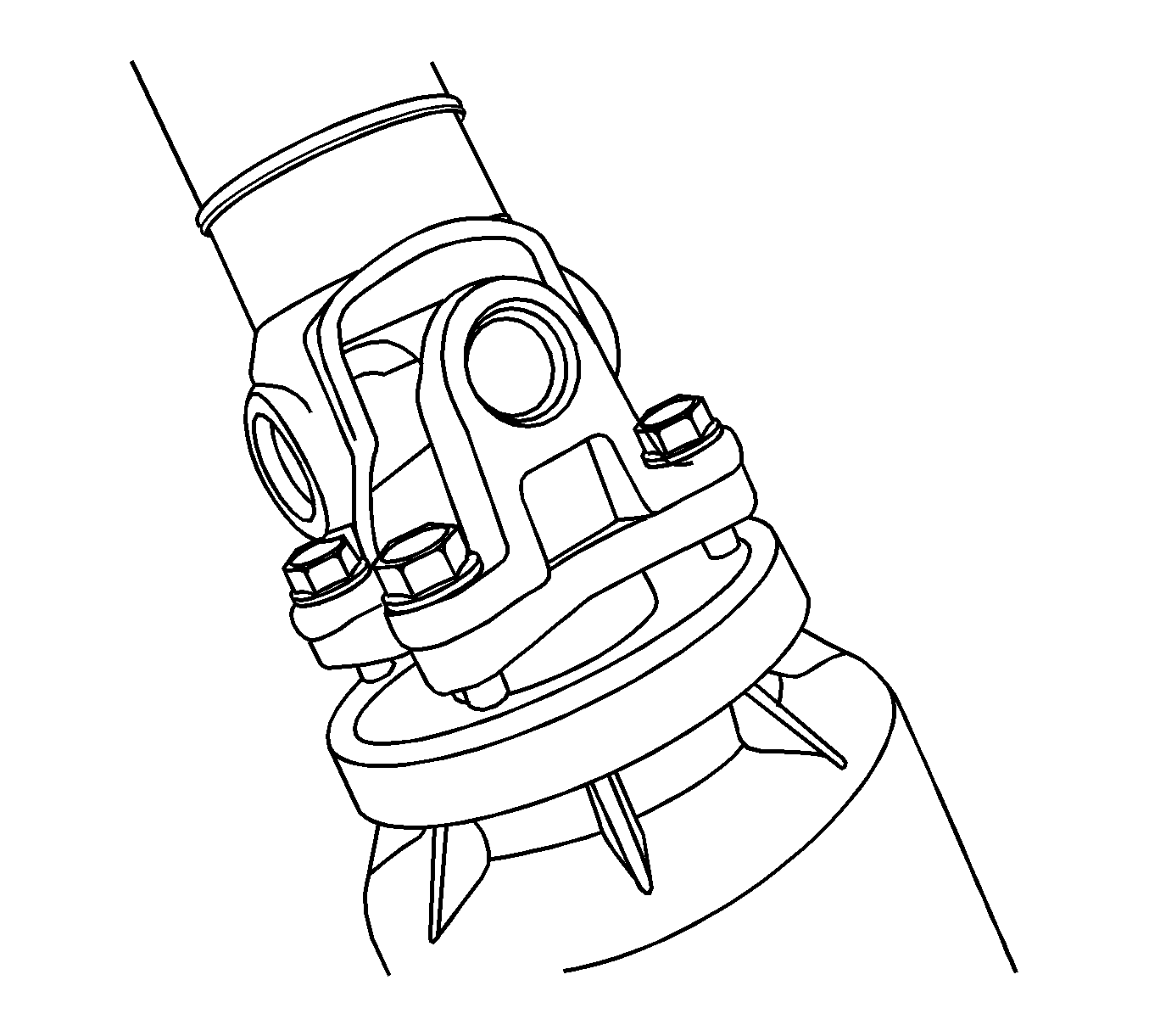
- Remove the propeller shaft assembly from the transfer case, if equipped. Refer to Propeller Shaft Replacement .
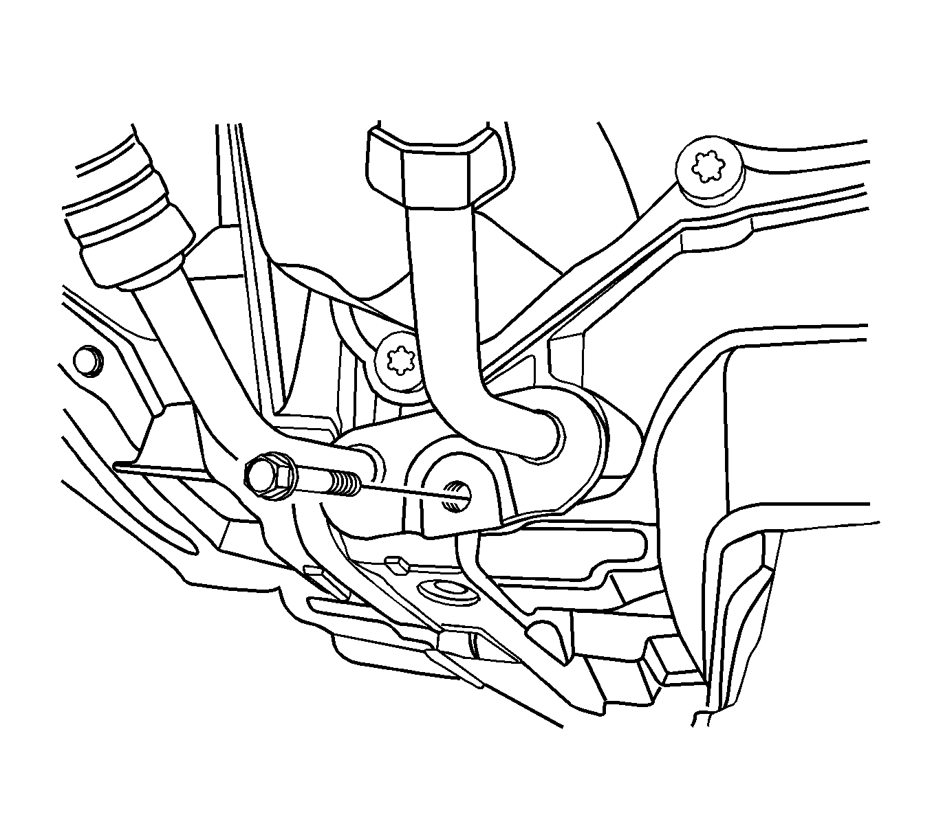
- Remove the cradle supporter bracket.
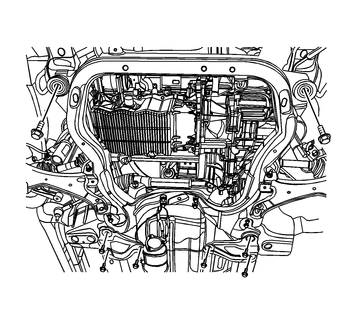
- Remove the cradle tightening bolts.
- Lower the vehicle and position the engine assembly on to the EN-48243 with the EN-48244 to the cradle.
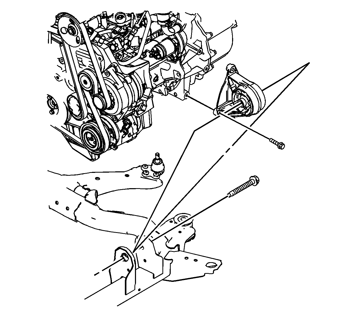
- Remove the engine mount bolt from the engine mount bracket.
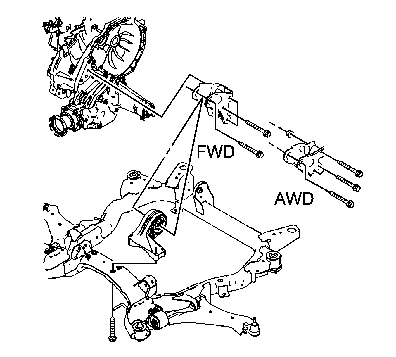
- Remove the transaxle mount bolt from the transaxle.
- Tighten the engine assembly using by hoist, etc.
- Remove the transaxle front mount.
- Remove the transaxle rear mount.
- Remove the engine and transaxle.
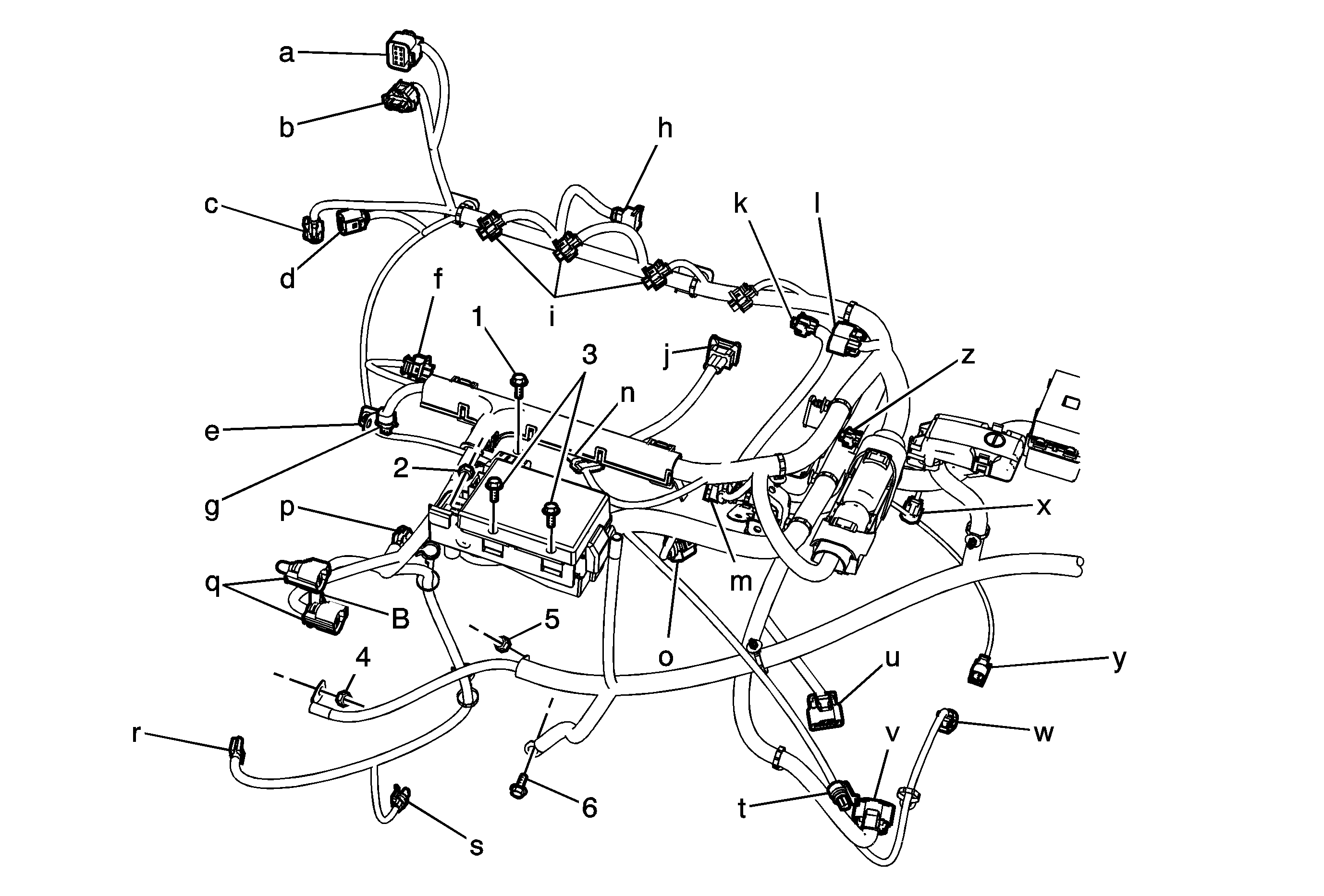
| • | Disconnect the fuel heater wiring connector (a). |
| • | Disconnect the mass air flow sensor (MAF) connector (b). |
| • | Disconnect the exhaust temperature sensor wiring connector (c). |
| • | Disconnect the DPF pressure sensor connector (d). |
| • | Disconnect the engine oil pressure switch connector (e). |
| • | Disconnect the common rail pressure sensor connector (f). |
| • | Disconnect the coolant temperature sensor connector (g). |
| • | Disconnect the EGR vacuum solenoid connector (h). |
| • | Disconnect the fuel injector connector (i). |
| • | Disconnect the camshaft position sensor (CMP) connector (j). |
| • | Disconnect the turbocharger actuator connector (k). |
| • | Disconnect the glow plug wire connector (l). |
| • | Disconnect the booster pressure (T-MAP) sensor connector (m) |
| • | Disconnect the common rail regulator connector (n). |
| • | Disconnect the ETC body connector (o). |
| • | Disconnect the fuel injection pump connector (p). |
| • | Disconnect the cooling fan connectors (q). |
| • | Disconnect the A/C compressor connector (r). |
| • | Disconnect the starter solenoid wiring connector (s). |
| • | Disconnect the A/C pressure sensor connector (t). |
| • | Disconnect the transaxle range (TR) switch connector, if auto-transaxle (u). |
| • | Disconnect the transaxle wiring electrical connector, if auto-transaxle (v). |
| • | Disconnect the input speed sensor electrical connector, if auto-transaxle (w). |
| • | Disconnect the output speed sensor electrical connector, if auto-transaxle (x). |
| • | Disconnect the speed sensor connector, if manual-transaxle (y). |
| • | Disconnect the crankshaft position sensor (z). |
| • | Disconnect the generator connector (B). |
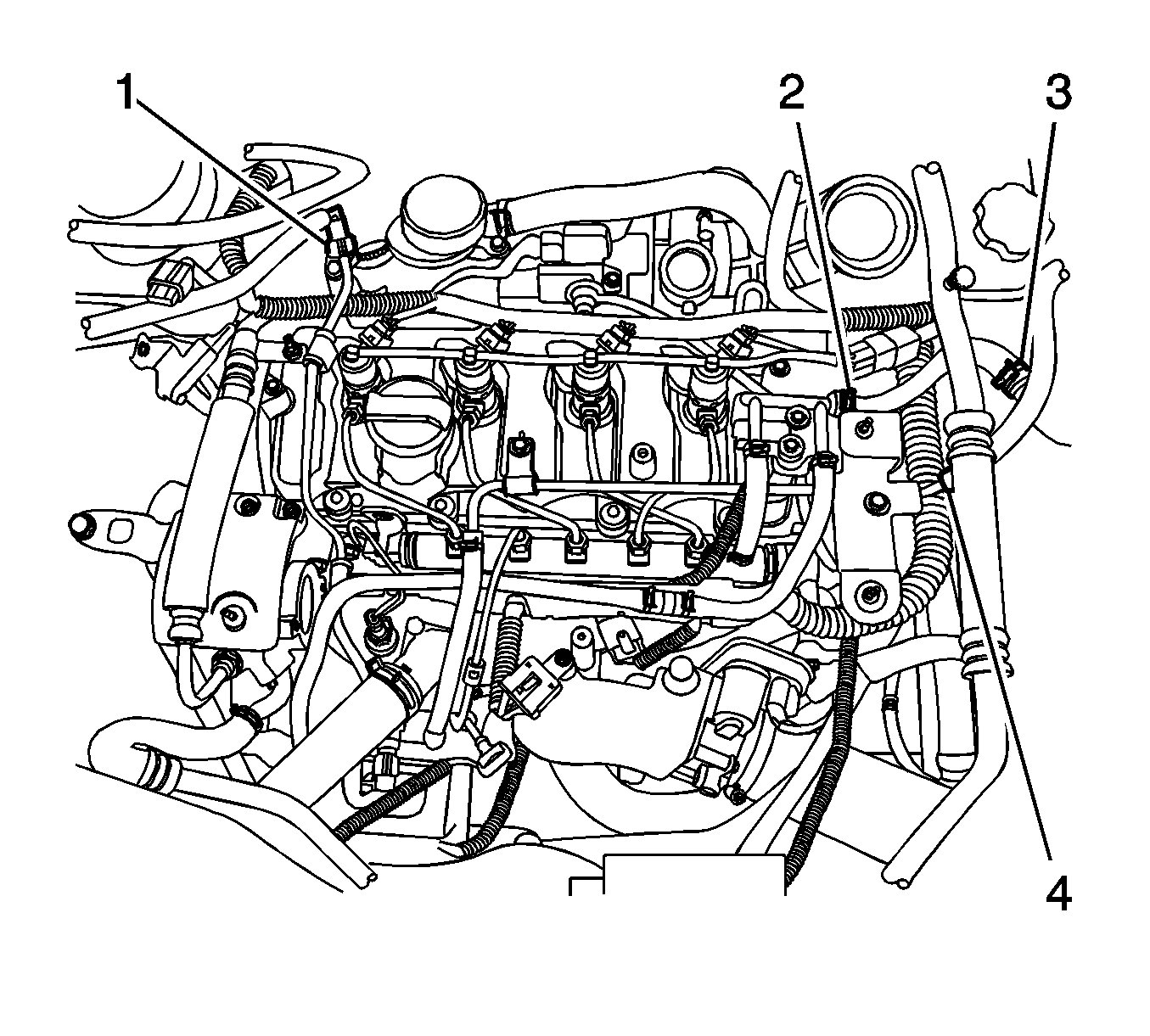
| 11.1. | Remove the engine splice pack tighten bolt from the intake manifold (1). |
| 11.2. | Remove the glow plug module (2). |
| 11.3. | Remove the glow plug fuse box (3). |
| 11.4. | Remove the generator B+ connector nut (4). |
| 11.5. | Remove the starter solenoid connector nut (5). |
| 11.6. | Remove the engine ground bolt (6). |
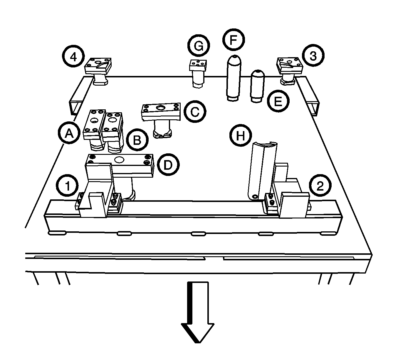
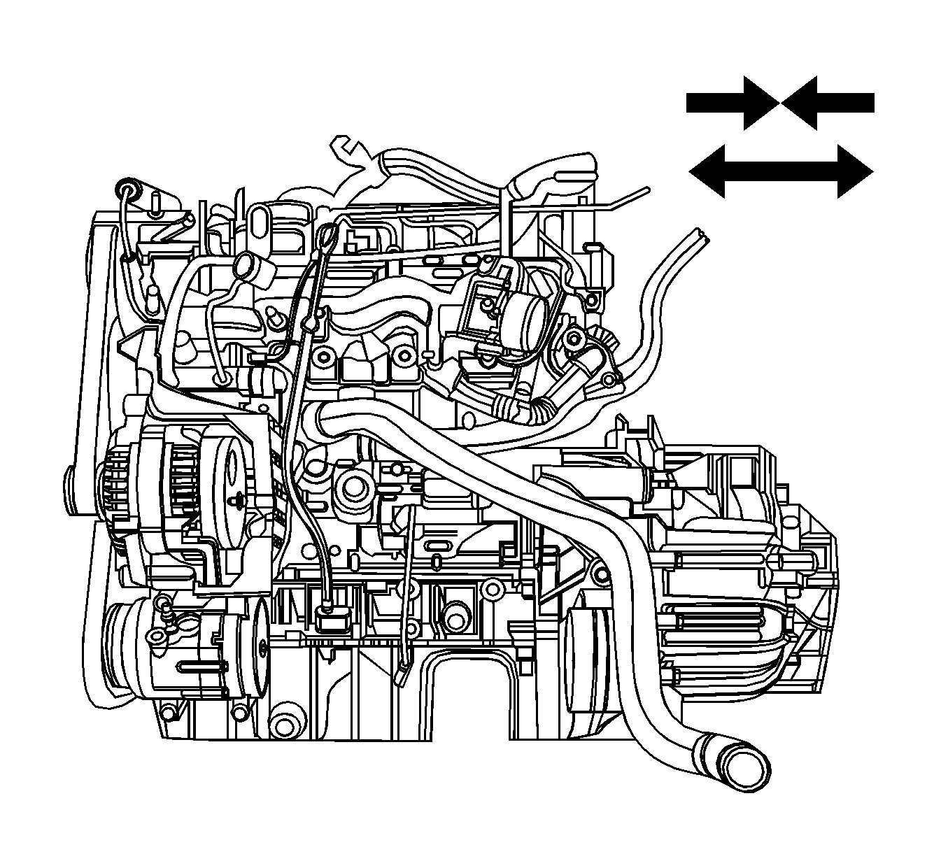
Important: Make sure all components are set on the exact position of the EN-48243 with EN-48244 .
| • | 1-4 : Cradle Supporter |
| • | Diesel Engine Oil Pan Supporter |
| • | FAM II 2.4L Diesel Engine Oil Pan Supporter |
| • | HFV6 3.2L Engine Oil Pan Supporter |
| • | Manual Transaxle Supporter |
| • | Automatic Transaxle Supporter |
| • | Transfer Case Supporter (M/T & A/T) |
| • | Transaxle Mount Supporter (M/T & A/T) |
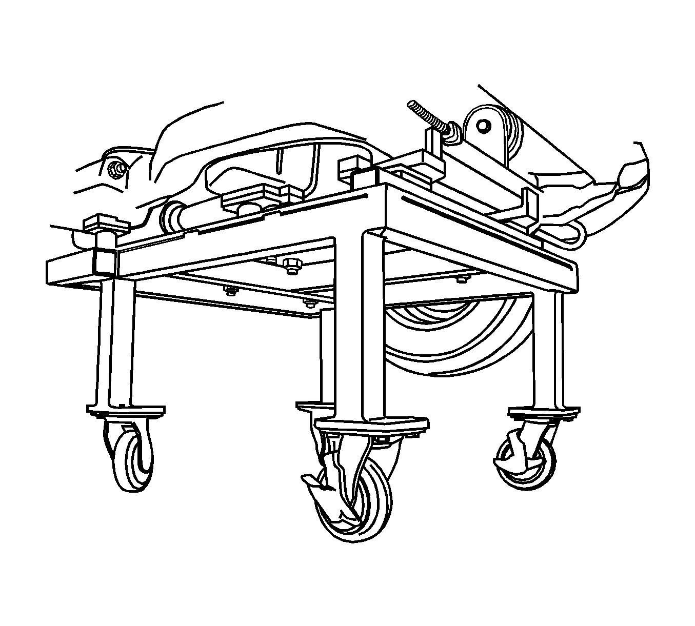
Important: Only lower the vehicle far enough to take the weight off the engine and transaxle mount, or damage to the mount and pallet/pallet supporter failure may occur.
Installation Procedure
- Install the transaxle to engine assembly.
- Install the cradle on the EN-48243 with the EN-48244 and then assemble the engine and the transaxle onto the cradle.
- Lower the vehicle and position the engine and transaxle assembly with the cradle attached on to the EN-48243 with the EN-48244 to the vehicle.
- Install the transaxle rear mount.
- Install the transaxle front mount.
- Install the transaxle mount.
- Install the engine mount bolt.
- Remove the EN-48243 with the EN-48244 from the vehicle.
- Install the cradle to body mounting bolts.
- Install the cradle support bracket retaining bolts.
- Connect the engine wiring harness.
- Install the engine hardware and components as follows:
Notice: Refer to Fastener Notice in the Preface section.

Tighten
| • | Tighten the transaxle tightening bolts to 75 N·m (55.3 lb ft). |
| • | Tighten the oil pan flange-to-transaxle bolts to 50 N·m (36.9 lb ft). |


Tighten
Tighten the transaxle rear mount bolt to 90 N·m (66.4 lb ft).

Tighten
Tighten the transaxle front mount bolt to 90 N·m (66.4 lb ft).

Tighten
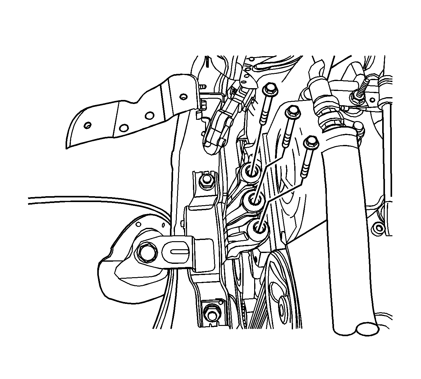
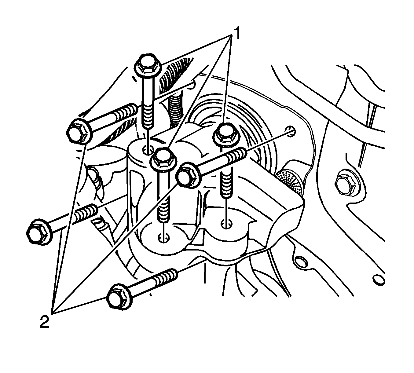
| • | Tighten the transaxle mount assembly retaining bolts (2) to 37 N·m (27 lb ft). |
| • | Tighten the transaxle mount bracket retaining bolts (1) to 50 N·m (37 lb ft). |

Tighten
Tighten the engine mount bracket retaining bolts to 50 N·m (37 lb ft).

Tighten
Tighten the cradle mounting bolts to 155 N·m (114.3 lb ft).
Tighten
Tighten the cradle support bracket bolts to 50 N·m (36.9 lb ft).

| • | Connect the fuel heater wiring connector (a). |
| • | Connect the mass air flow sensor (MAF) connector (b). |
| • | Connect the exhaust temperature sensor wiring connector (c). |
| • | Connect the DPF pressure sensor connector (d). |
| • | Connect the engine oil pressure switch connector (e). |
| • | Connect the common rail pressure sensor connector (f). |
| • | Connect the coolant temperature sensor connector (g). |
| • | Connect the EGR vacuum solenoid connector (h). |
| • | Connect the fuel injector connector (i). |
| • | Connect the camshaft position sensor (CMP) connector (j). |
| • | Connect the turbocharger actuator connector (k). |
| • | Connect the glow plug wire connector (l). |
| • | Connect the booster pressure (T-MAP) sensor connector (m) |
| • | Connect the common rail regulator connector (n). |
| • | Connect the ETC body connector (o). |
| • | Connect the fuel injection pump connector (p). |
| • | Connect the cooling fan connectors (q). |
| • | Connect the A/C compressor connector (r). |
| • | Connect the starter solenoid wiring connector (s). |
| • | Connect the A/C pressure sensor connector (t). |
| • | Connect the transaxle range (TR) switch connector, if auto-transaxle (u). |
| • | Connect the transaxle wiring electrical connector, if auto-transaxle (v). |
| • | Connect the input speed sensor electrical connector, if auto-transaxle (w). |
| • | Connect the output speed sensor electrical connector, if auto-transaxle (x). |
| • | Connect the speed sensor connector, if manual-transaxle (y). |
| • | Connect the crankshaft position sensor (z). |
| • | Connect the generator connector (B). |
| 12.1. | Install the engine splice pack tighten bolt from the intake manifold (1). |
Tighten
Tighten the engine wiring harness splice pack tighten bolt to 15 N·m (11.1 lb ft).
| 12.2. | Install the glow plug module (2). |
Tighten
Tighten the glow plug module retaining nut to 14 N·m (10.3 lb ft).
| 12.3. | Install the glow plug fuse box (3). |
Tighten
Tighten the glow plug fuse box bolts to 10 N·m (88.5 lb in).
| 12.4. | Install the generator B+ connector nut (4). |
Tighten
Tighten the generator B+ connector nut to 25 N·m (18.4 lb ft).
| 12.5. | Install the starter solenoid connector nut (5). |
Tighten
Tighten the starter solenoid connector nut to 15 N·m (11.1 lb ft).
| 12.6. | Install the engine ground bolt (6). |
Tighten
Tighten the engine block ground bolt to 25 N·m (18.4 lb ft).
