Tools Required
| • | J 6125-1B Slide Hammer with Adapter |
| • | J 38868 Output Shaft Assembly Remover and Installer |
Removal Procedure
- Remove the battery tray. Refer to Battery Tray Replacement .
- Remove the shift control cable bracket. Refer to Shift Control Cable Bracket Replacement .
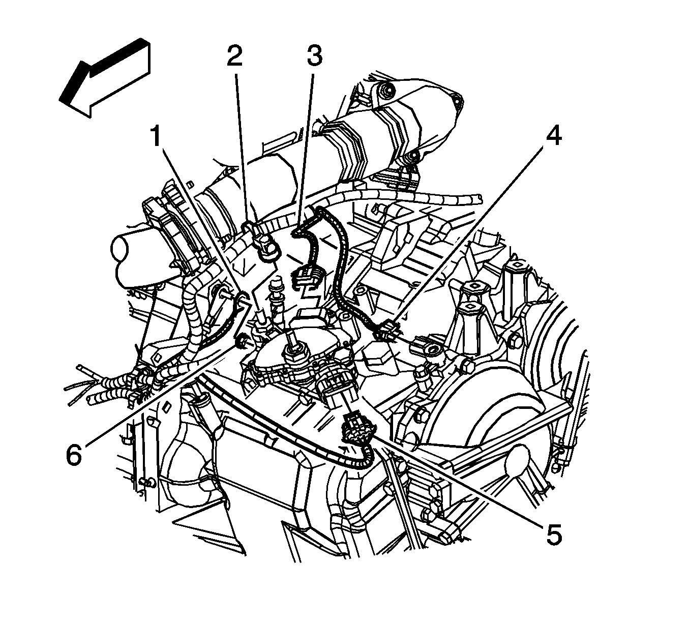
- Disconnect the electrical connector (4) from the input speed sensor.
- Disconnect the electrical connectors (3, 5) from the transaxle range switch.
- Remove the wire harness (2) from the transaxle range switch.
- Remove the nut (6) securing the battery negative cable and wire harness ground to the transaxle stud.
- Remove the battery negative cable and wire harness ground (1) from the transaxle stud.
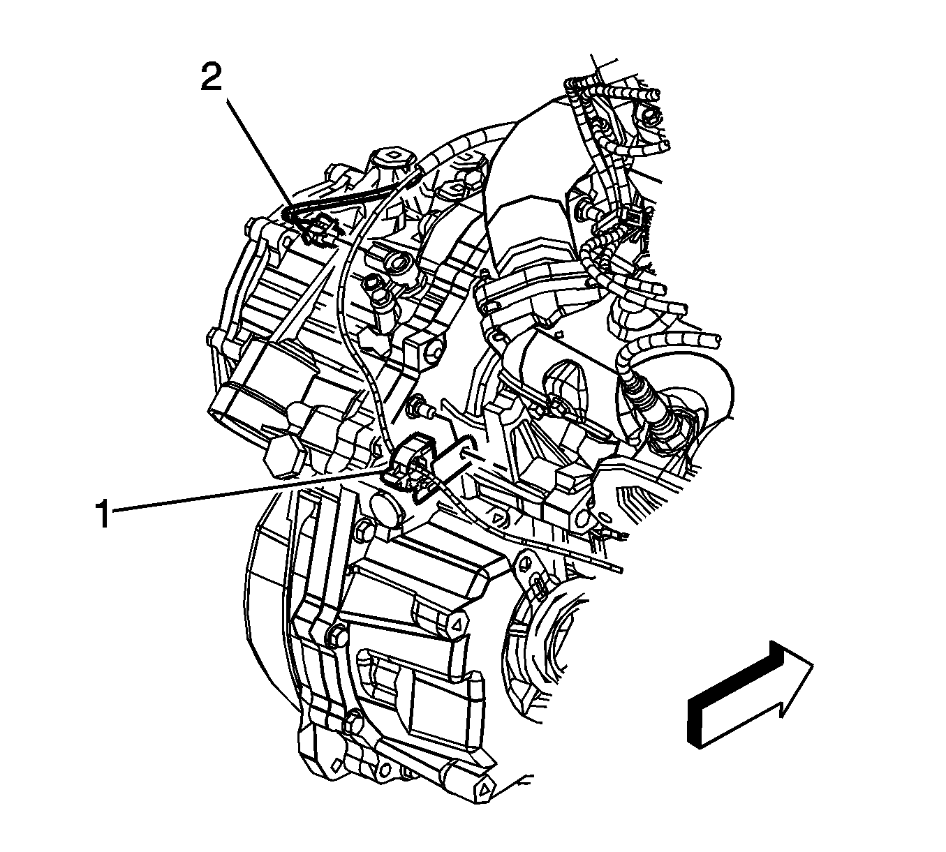
- Disconnect the electrical connector (2) from the output speed sensor.
- Remove the nut and fuel line retaining clip (1) from the transaxle.
- Disconnect the transaxle vent tube.
- Secure the wire harness, vent hose, and shift cable up away from the transaxle.
- Remove the upper 4 transaxle-to-engine bolts.
- Tie the radiator, air conditioning condenser and fan module assembly to the upper radiator support to keep the assembly with the vehicle when the frame and drivetrain are removed.
- Install the engine support fixture.
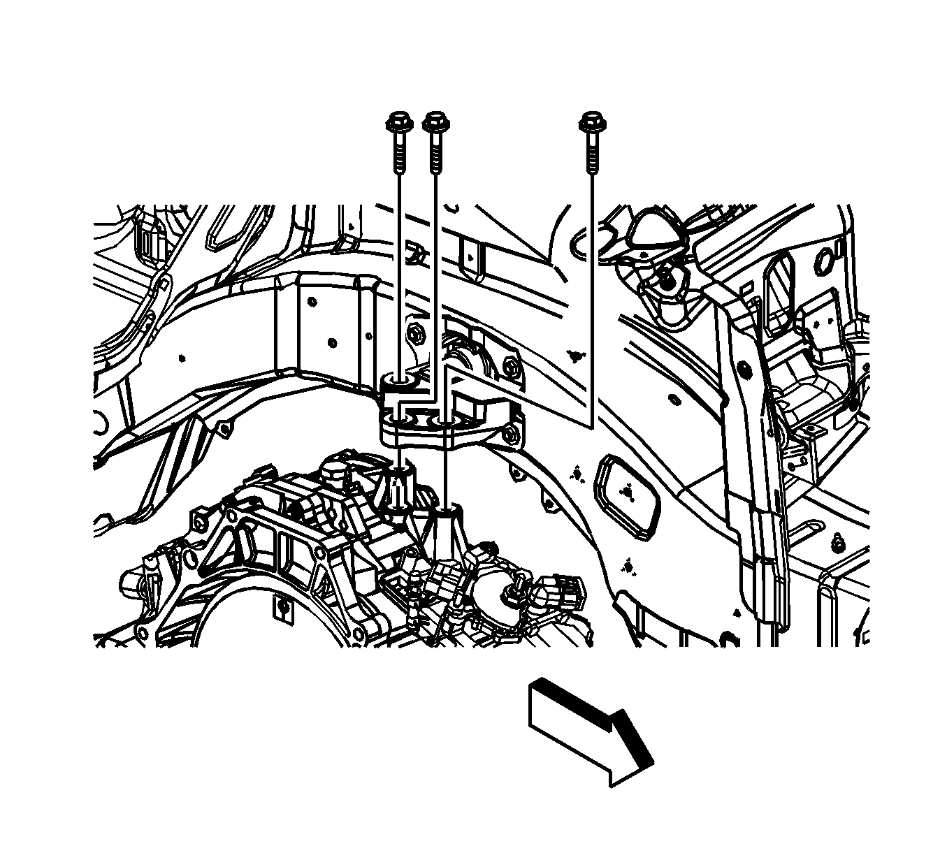
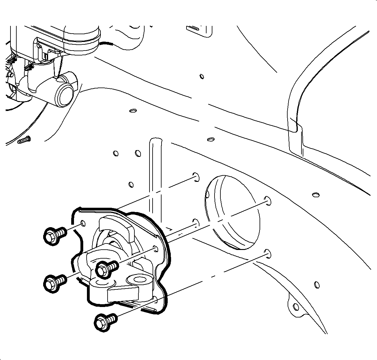
- Remove the left hand transaxle mount-to-transaxle bolts.
- Remove the left hand transaxle mount-to-side rail bolts.
- Remove the left hand transaxle mount from the vehicle.
- Raise and support the vehicle. Refer to Lifting and Jacking the Vehicle .
- Remove both front wheels. Refer to Tire and Wheel Removal and Installation .
- Remove the left and right side engine splash shields.
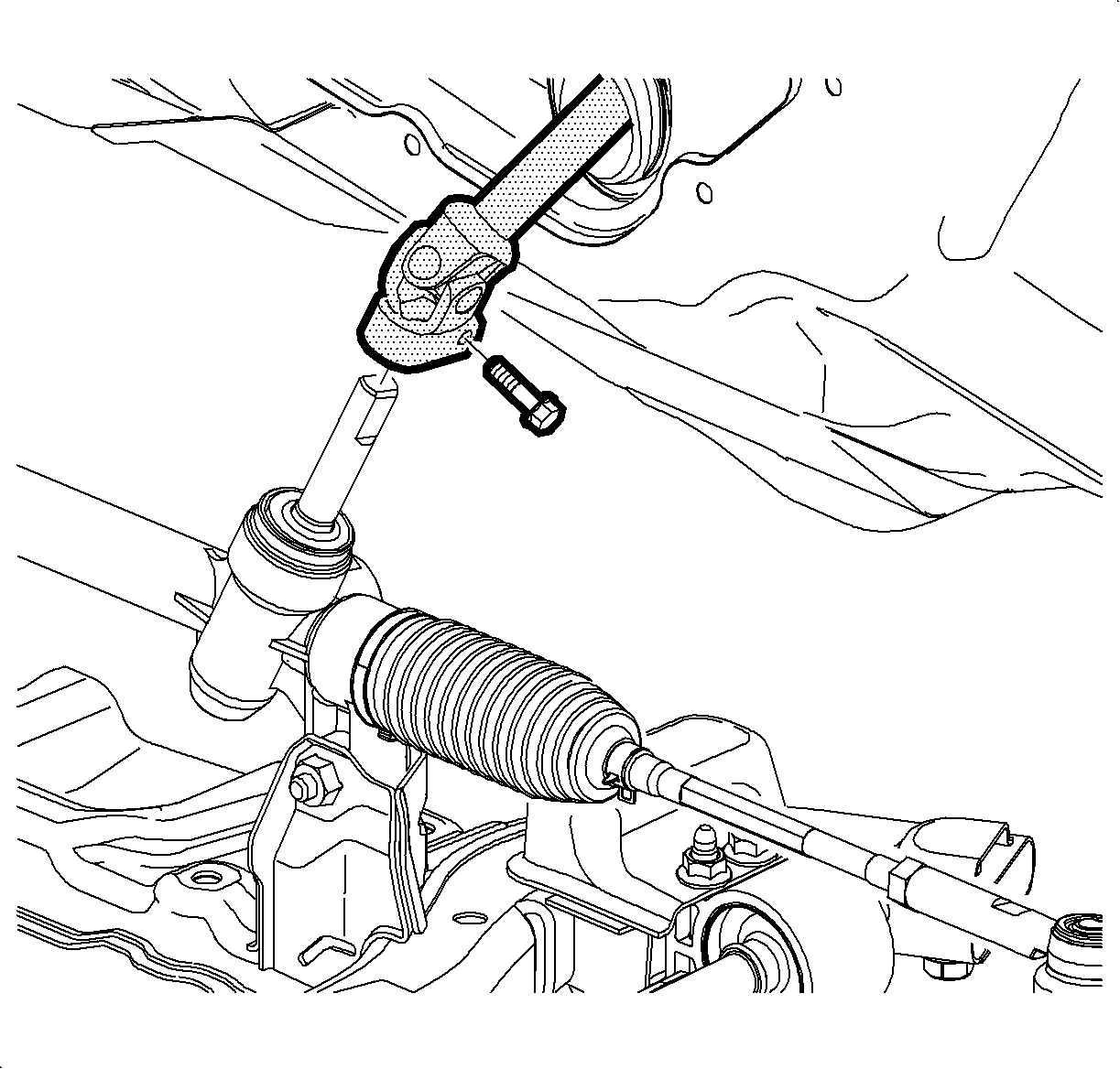
- Remove the steering intermediate shaft pinch bolt and discard the bolt.
- Disconnect the steering intermediate shaft from the steering gear.
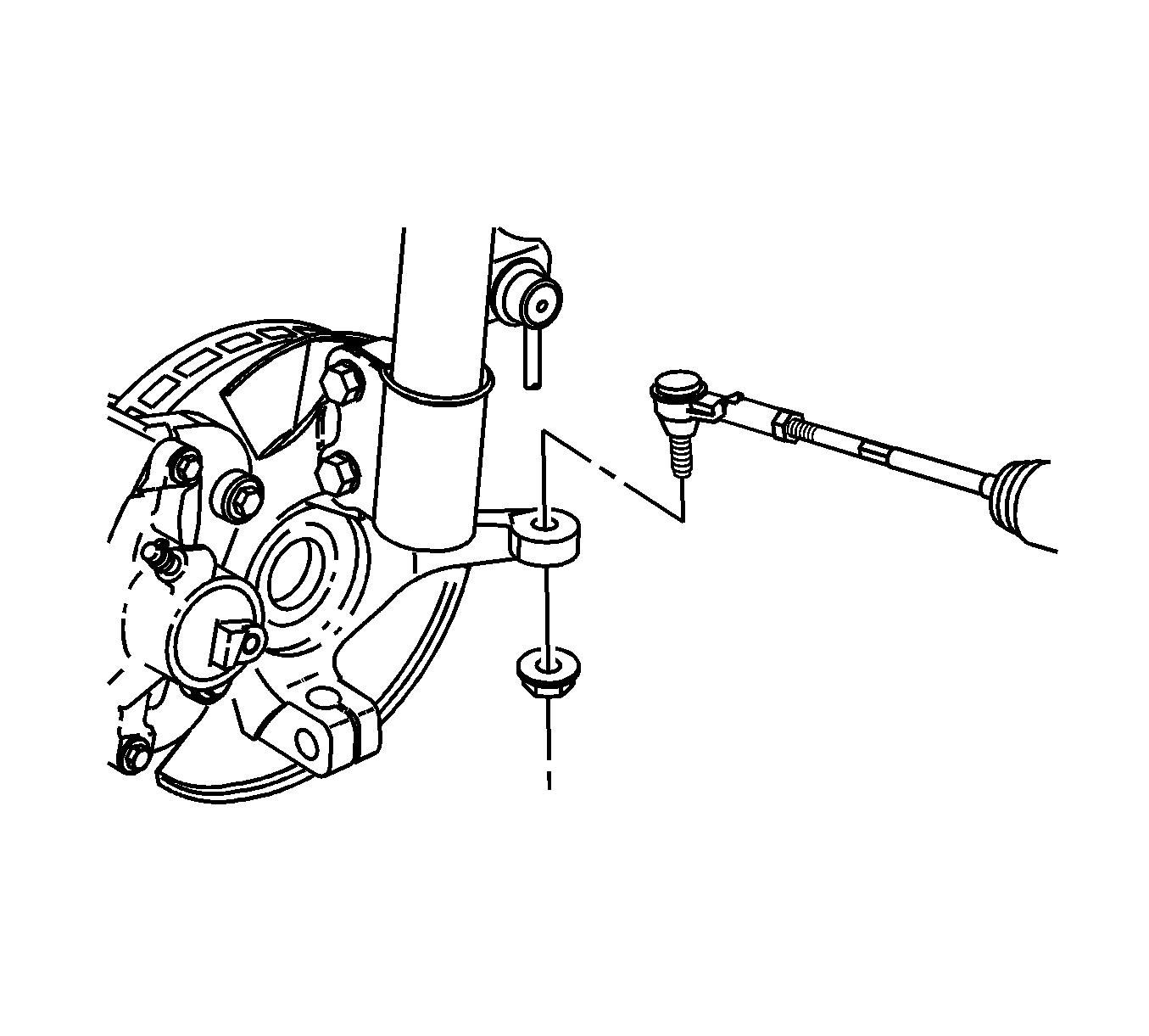
- Remove the right and left outer tie rod ends from the steering knuckles. Refer to Rack and Pinion Outer Tie Rod End Replacement .
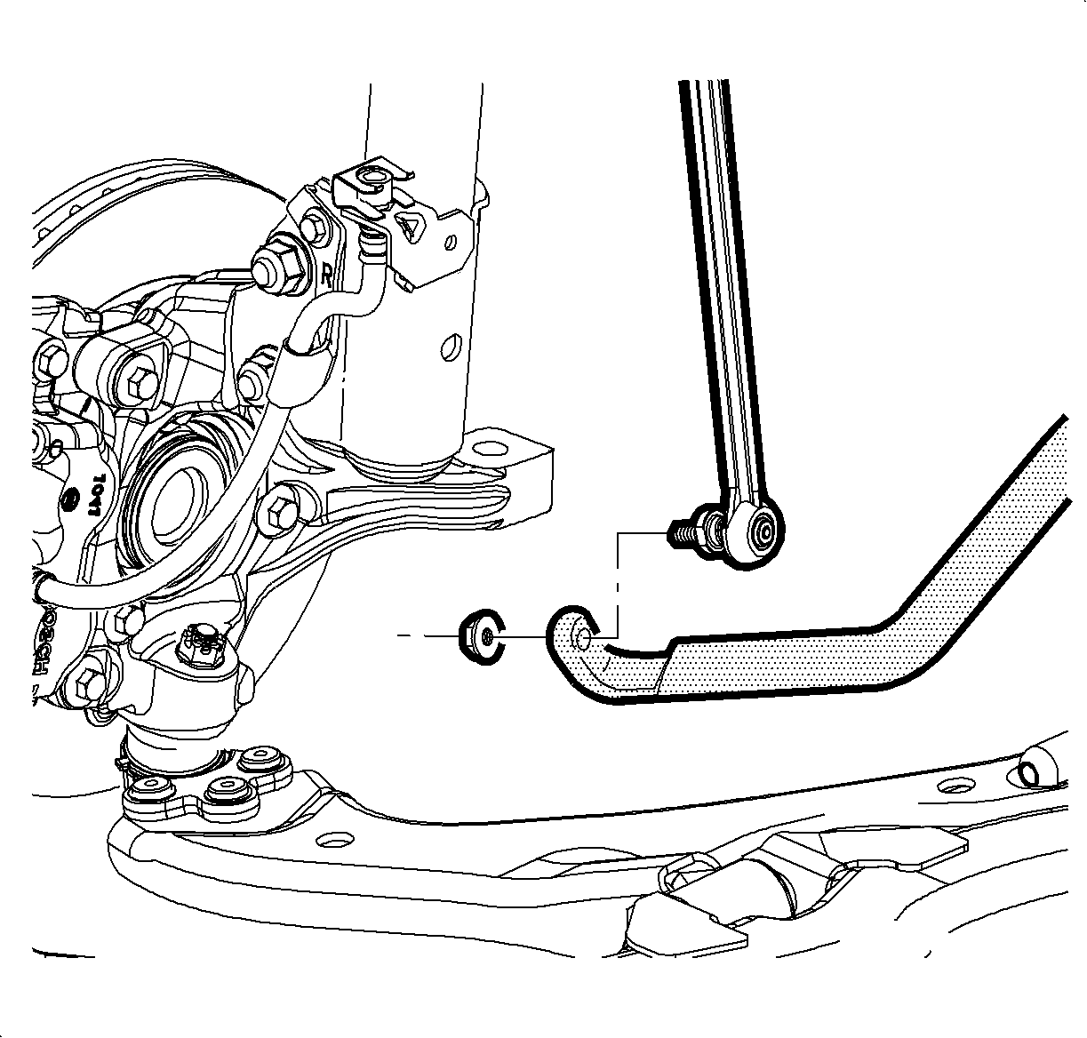
- Remove the right and left stabilizer shaft links from the stabilizer shaft. Refer to Stabilizer Shaft Link Replacement .
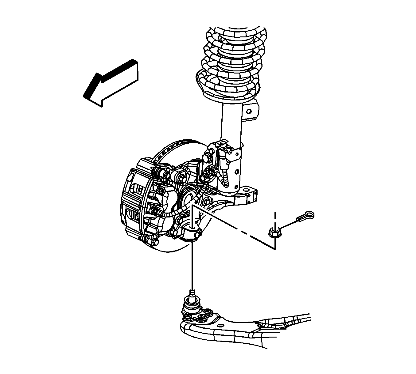
- Remove the right and left lower ball joints from the steering knuckles. Refer to Lower Control Arm Replacement .
- Remove the front bumper fascia air deflector.
- Drain the transaxle fluid. Refer to Transmission Fluid Replacement .
- Remove the transaxle oil cooler lines and seals from the transaxle. Refer to Transmission Fluid Cooler Pipe Seal Replacement .
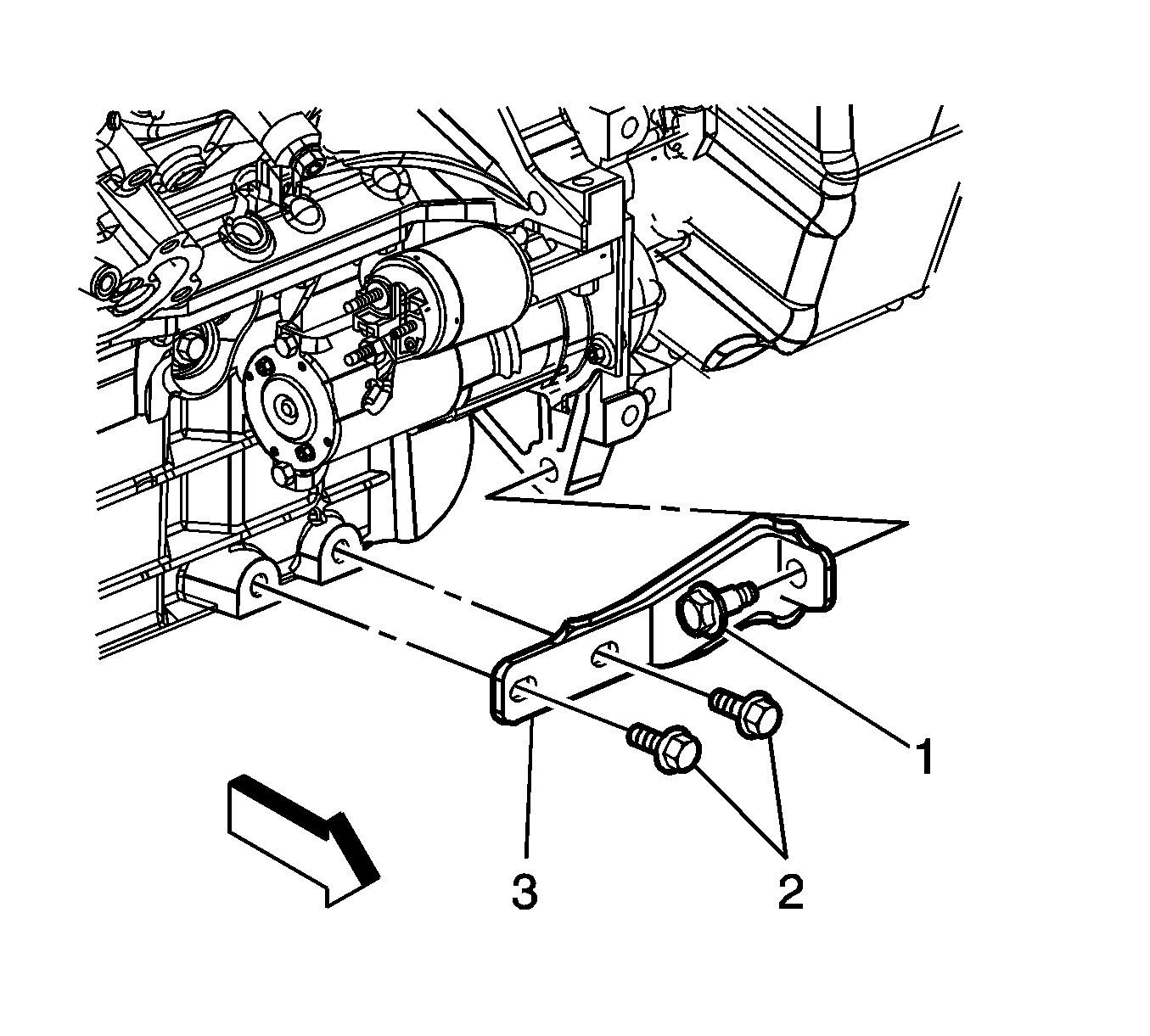
- Remove the engine-to-transaxle brace bolts (1, 2) and brace (3).
- Remove the starter motor.
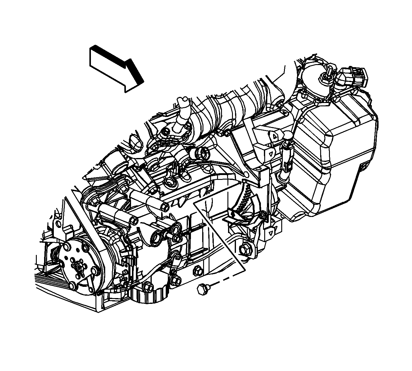
- Turn the crankshaft balancer bolt clockwise to gain access to the torque converter-to-flywheel bolts through the starter motor hole.
- Remove the torque converter-to-flywheel bolts.
- Remove the front engine mount.
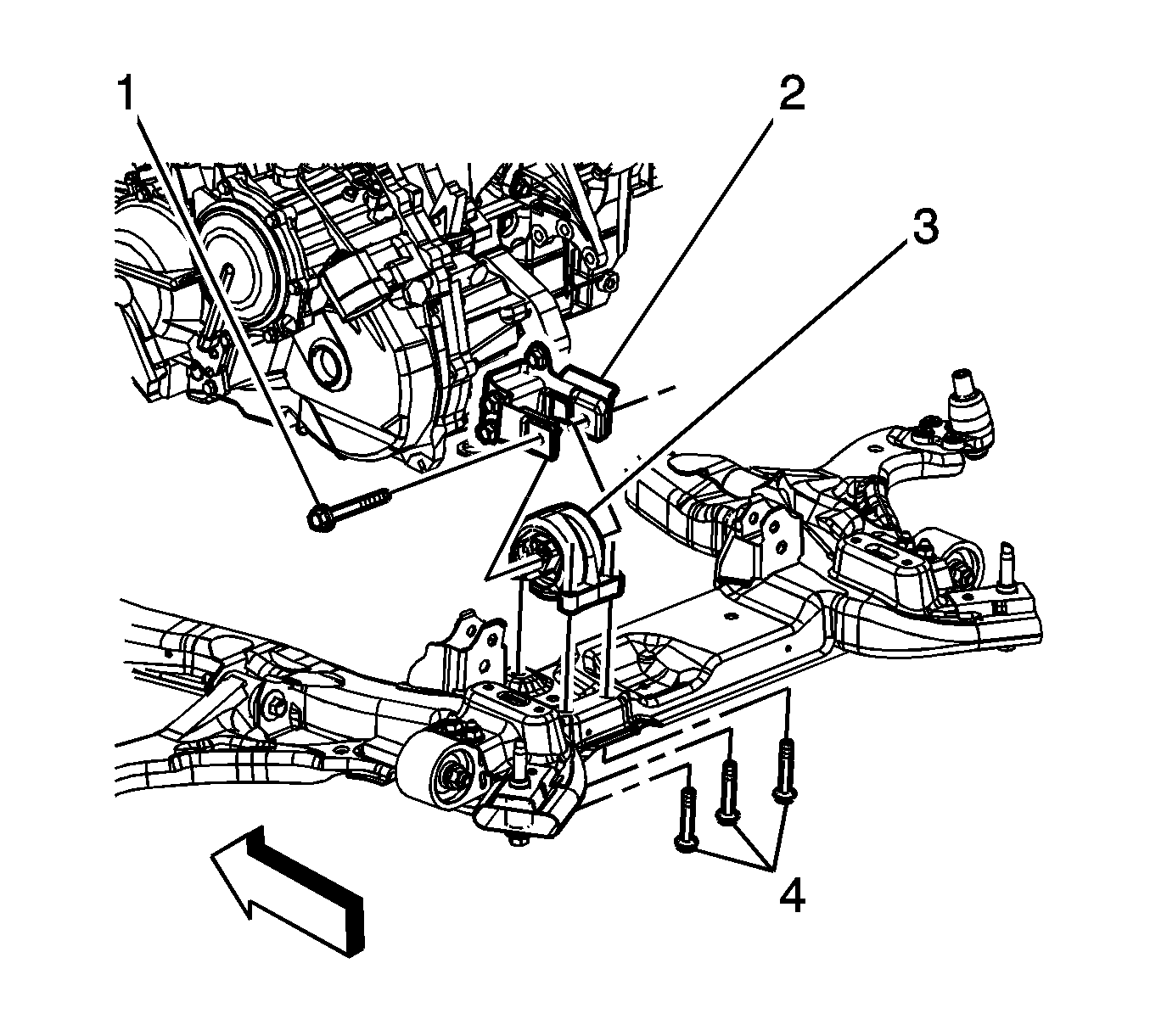
- Remove the through bolt (1) from the rear transaxle mount (3) and bracket (2).
- Place a universal frame support fixture under the frame.
- Lower the vehicle until the frame contacts the frame support fixture.
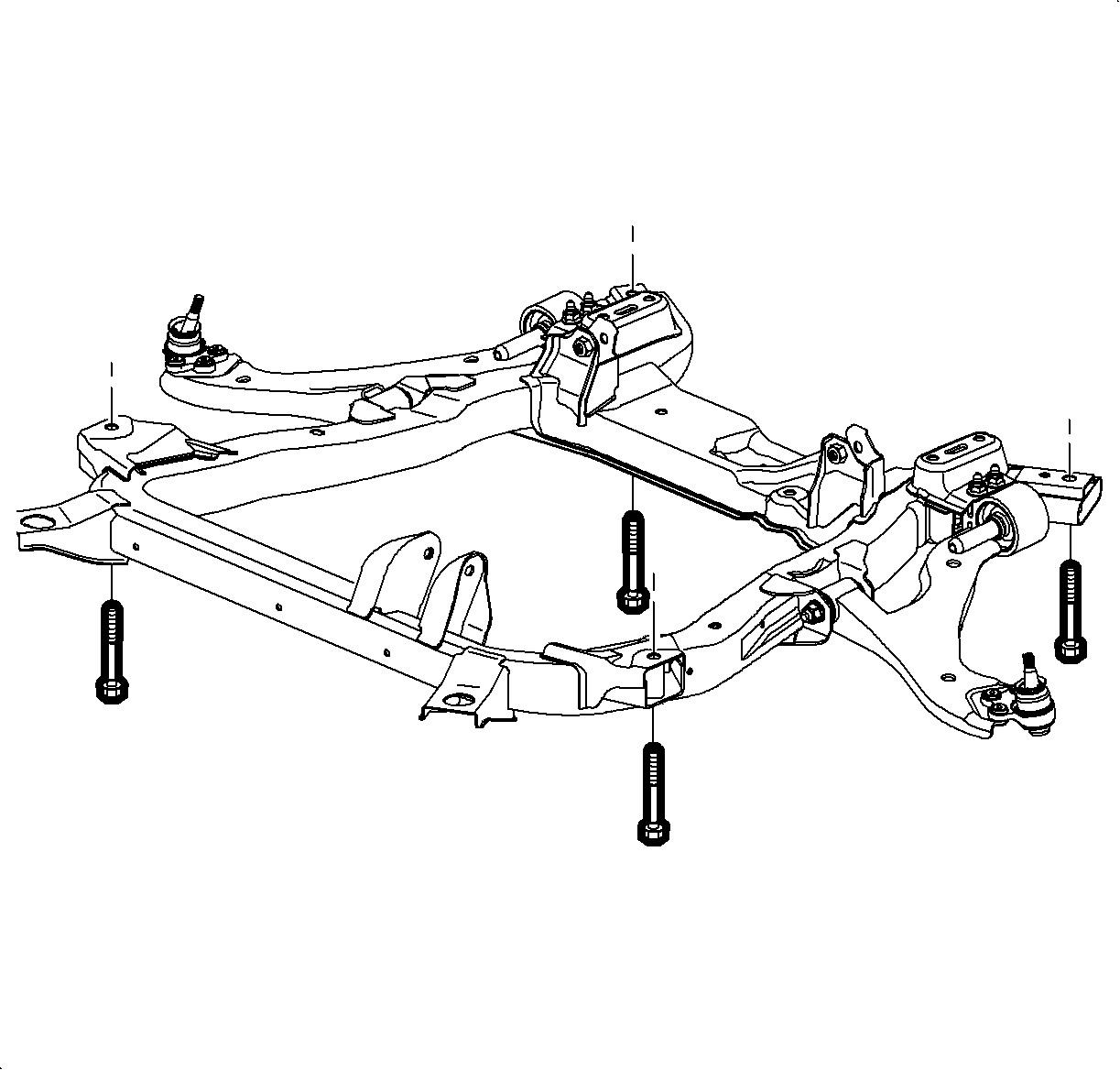
- Remove the frame-to-body bolts. Discard the bolts.
- Raise the vehicle up away from the frame and remove the frame from under the vehicle.
- Disconnect the right and left drive shafts from the transaxle. Refer to Front Wheel Drive Shaft Replacement . Secure both drive shafts out of the way.
- If vehicle is equipped with all wheel drive (AWD) complete the following steps:
- Support the transaxle with a suitable transaxle jack.
- Remove the 4 lower transaxle-to-engine bolts.
- Slide the transaxle away from the engine until the transaxle torque-converter clears the flywheel.
- If equipped with a drive axle seal dust cover, discard it and do not replace it.
- Lower the transaxle away from the vehicle.
- If the vehicle is equipped with AWD complete the following steps:
- If the vehicle is equipped with front wheel drive (FWD) complete the following steps:
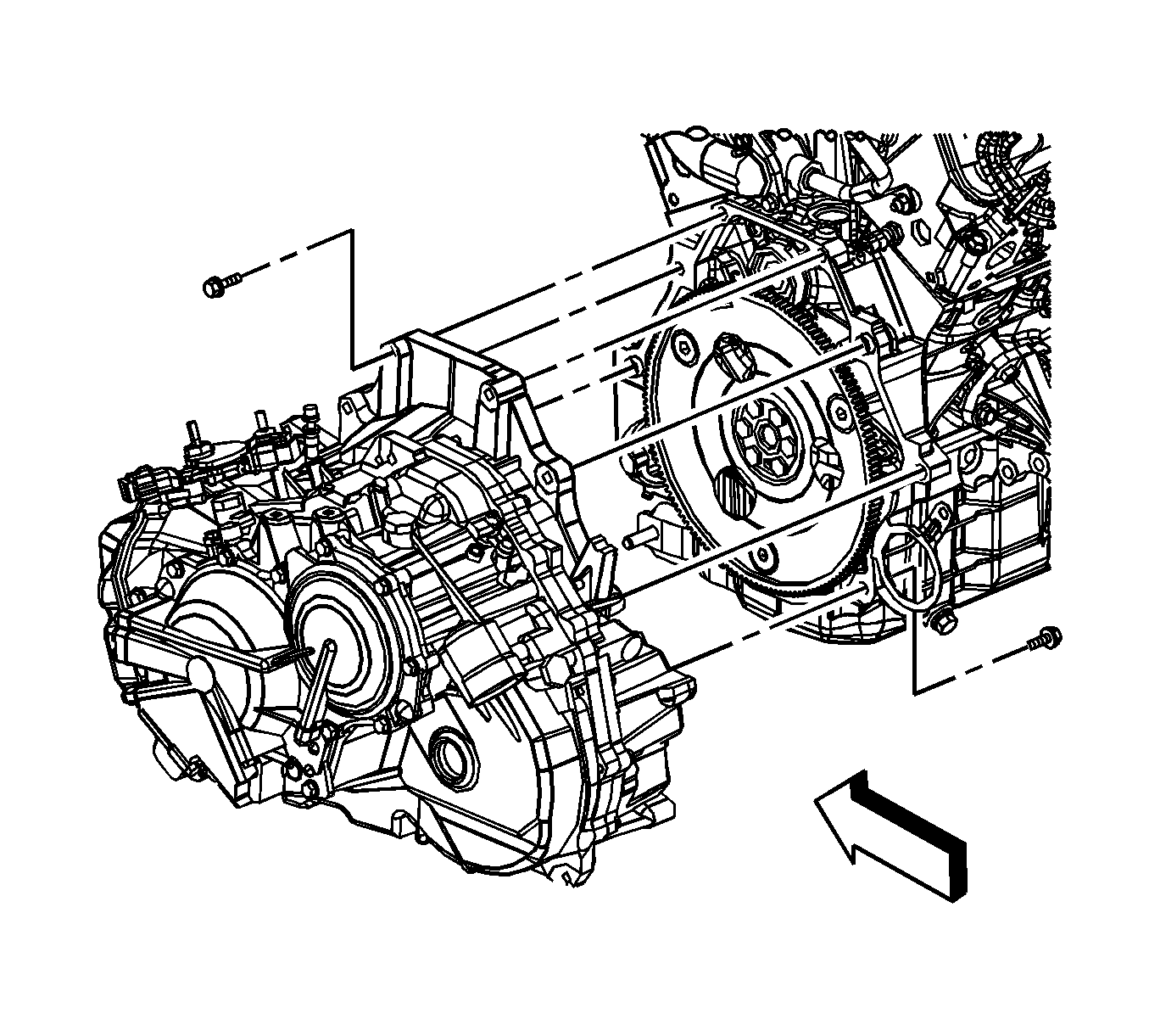
Important: Mark the relation of the flywheel to torque converter for reassembly.
| 40.1. | Remove the rear propeller shaft. Refer to Propeller Shaft Replacement . |
| 40.2. | Remove the transfer case mounting bracket. |
| 40.3. | Disconnect the vent hose from the top of the transfer case. |

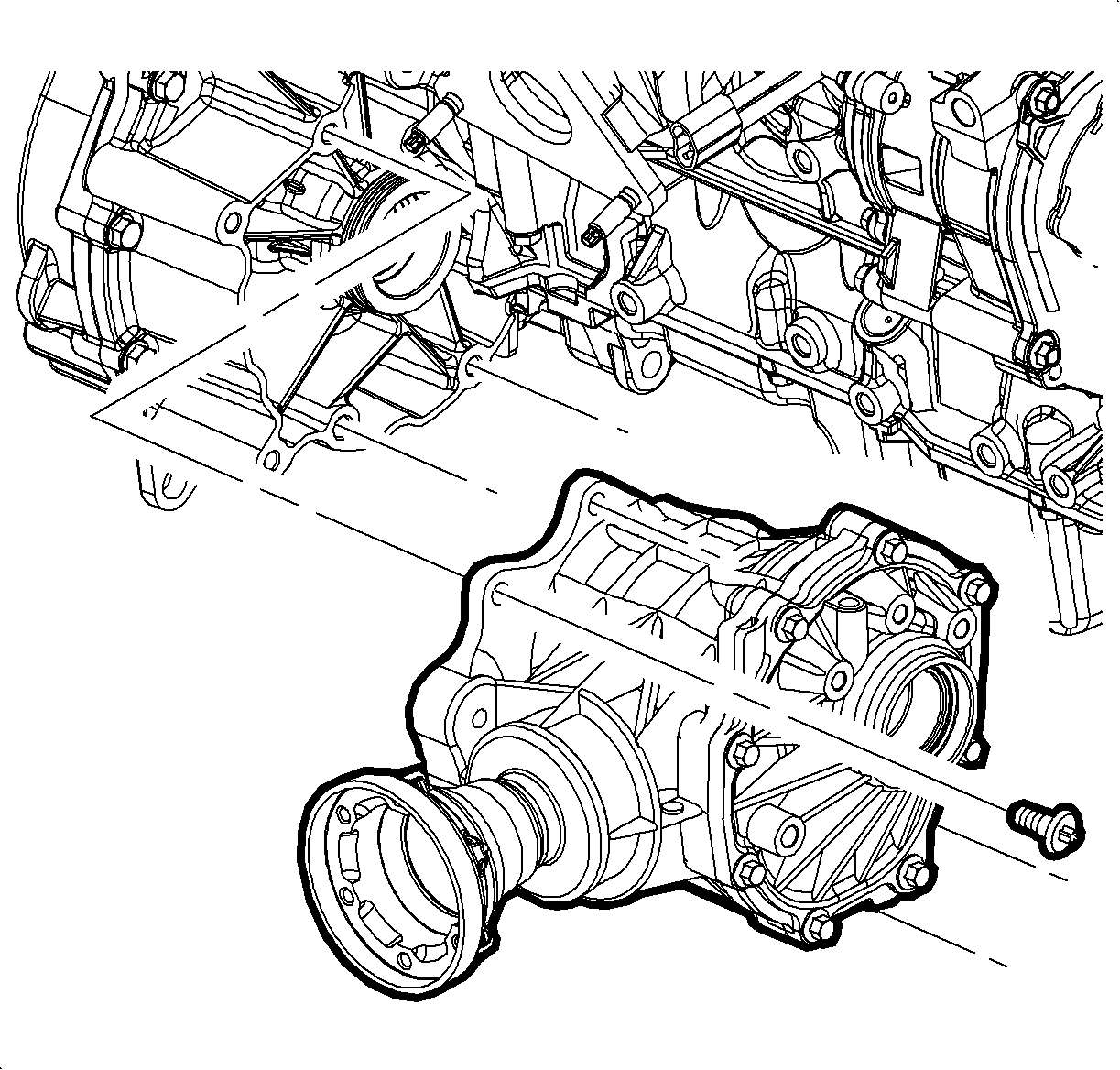
| 46.1. | Remove the retaining ring from the stub shaft for tool installation. Discard the retainer ring. |
| 46.3. | Remove the bolts securing the transfer case to the transaxle. |
| 46.4. | Remove the transfer case from the transaxle. |
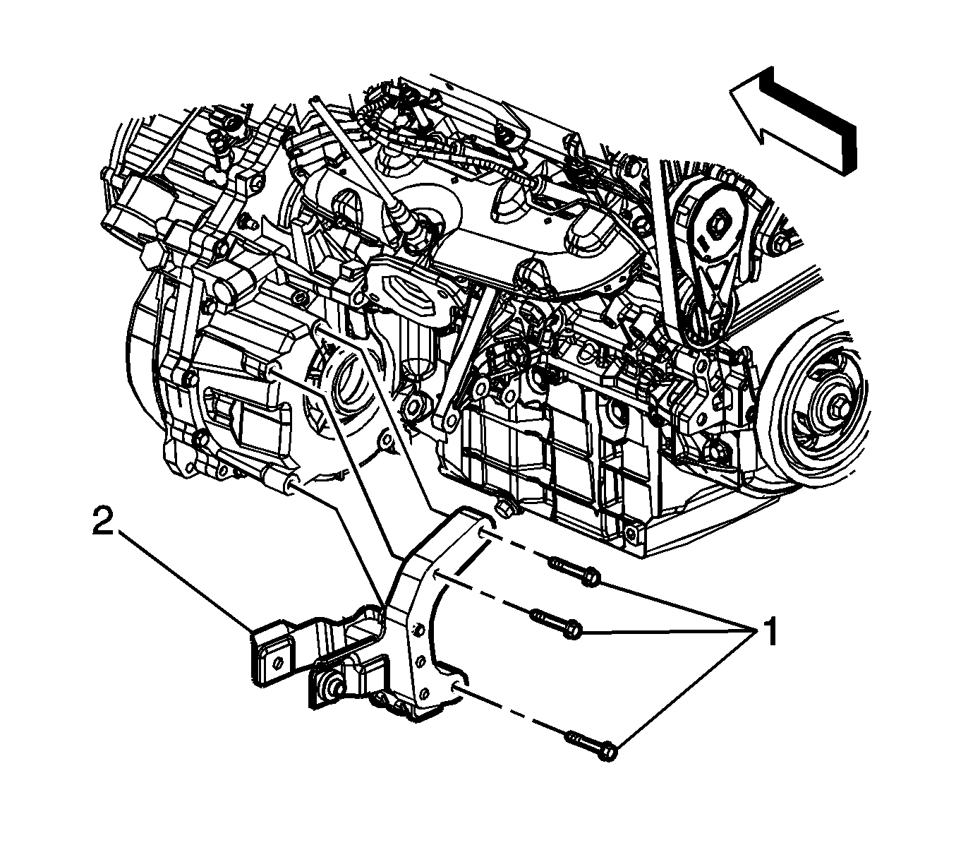
| 47.1. | Remove the bolts (1) securing the rear transaxle mount bracket to the transaxle. |
| 47.2. | Remove the rear transaxle mount bracket (2) from the transaxle. |
Installation Procedure
- If the vehicle is equipped with FWD complete the following steps:
- If the vehicle is equipped with AWD complete the following steps:
- Raise the transaxle up into the vehicle engine compartment.
- Align and install the transaxle to the engine.
- Install the 4 lower transaxle-to-engine bolts.
- If the vehicle is equipped with AWD complete the following steps:
- Install the right and left drive shafts to the intermediate shaft and transaxle. Refer to Front Wheel Drive Shaft Replacement .
- Install the frame to the vehicle.
- Install NEW frame-to-body bolts.
- Install the bolt (1) through the rear transaxle mount (3) and transaxle mount bracket (2).
- Install the front engine mount.
- Turn the crankshaft balancer bolt clockwise to gain access to the torque converter-to-flywheel bolts through the starter motor hole.
- Install the torque converter to flywheel bolts.
- Install the starter motor.
- Install the engine-to-transaxle brace (3).
- Install the engine-to-transaxle brace bolts (1, 2).
- Install the transaxle oil cooler lines and seals to the transaxle. Refer to Transmission Fluid Cooler Pipe Seal Replacement .
- Install the front bumper fascia air deflector.
- Install the right and left lower ball joints to the steering knuckles. Refer to Lower Control Arm Replacement .
- Install the right and left stabilizer shaft links to the stabilizer shaft. Refer to Stabilizer Shaft Link Replacement .
- Install the right and left outer tie rod ends to the steering knuckles. Refer to Rack and Pinion Outer Tie Rod End Replacement .
- Connect the steering intermediate shaft to the steering gear.
- Install a NEW pinch bolt to the steering intermediate shaft.
- Install the right and left side engine splash shields.
- Install both front wheels. Refer to Tire and Wheel Removal and Installation .
- Lower the vehicle.
- Install the left hand transaxle mount to the vehicle.
- Install the left hand transaxle mount-to-side rail bolts.
- Install the left hand transaxle mount to transaxle bolts.
- Remove the engine support fixture.
- Untie the radiator, air conditioning condenser and fan module assembly from the upper radiator support .
- Install the upper 4 transaxle-to-engine bolts.
- Connect the transaxle vent tube.
- Connect the electrical connector (2) to the output speed sensor.
- Install the nut and fuel line retaining clip (1) to the transaxle.
- Install the battery negative cable and wire harness ground (1) to the transaxle stud.
- Install the nut (6) securing the battery negative cable and wire harness ground to the transaxle stud.
- Connect the electrical connectors (3, 5) to the transaxle range switch.
- Connect the electrical connector (4) from the input speed sensor.
- Install the shift control cable bracket. Refer to Shift Control Cable Bracket Replacement .
- Install the battery tray. Refer to Battery Tray Replacement .
- Fill the transaxle with fluid. Refer to Transmission Fluid Replacement .
Notice: Refer to Fastener Notice in the Preface section.

| 1.1. | Install the rear transaxle mount bracket (2) to the transaxle. |
| 1.2. | Install the bolts (1) securing the rear transaxle mount bracket to the transaxle. |
Tighten
Tighten the bolts to 55 N·m (41 lb ft).

| 2.1. | Install the transfer case to the transaxle. |
| 2.2. | Install the bolts securing the transfer case to the transaxle. |
Tighten
Tighten the bolts to 60 N·m (44 lb ft).
| 2.4. | Install a NEW retaining ring on the stub shaft |

Tighten
Tighten the bolts to 75 N·m (55 lb ft).
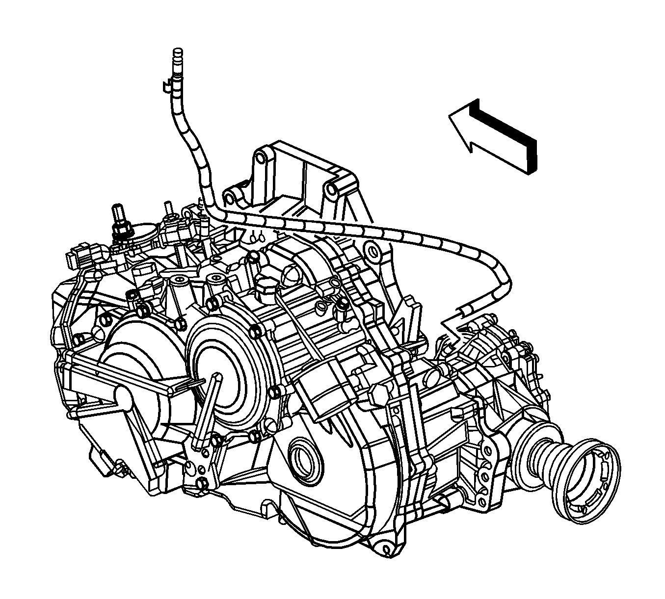
| 6.1. | Connect the vent hose to the top of the transfer case. |
| 6.2. | Install the transfer case mounting bracket. |
| 6.3. | Install the rear propeller shaft. Refer to Propeller Shaft Replacement . |

Tighten
Tighten the bolts to 155 N·m (114 lb ft).

Tighten
Tighten the bolt (1) to 110 N·m (80 lb ft).

Important: Align the reference marks on the flywheel and torque converter.
Tighten
Tighten the bolt to 60 N·m (44 lb ft).

Tighten
Tighten the bolts to 50 N·m (37 lb ft).


Tighten
Tighten the bolt to 34 N·m (25 lb ft).

Tighten
Tighten the bolts to 37 N·m (27 lb ft).

Tighten
Tighten the bolts to 50 N·m (37 lb ft).

Tighten
Tighten the bolts to 75 N·m (55 lb ft).

Tighten
Tighten the nut to 25 N·m (18 lb in).

Tighten
Tighten the nut to 45 N·m (33 lb ft).
