For 1990-2009 cars only
Removal Procedure
- Disconnect the negative battery cable. Refer to Battery Negative Cable Disconnection and Connection.
- Remove the driver information display bezel. Refer to Driver Information Display Bezel Replacement.
- Remove the clock. Refer to Clock Replacement.
- Disconnect the auxiliary HVAC enabling switch electrical connector.
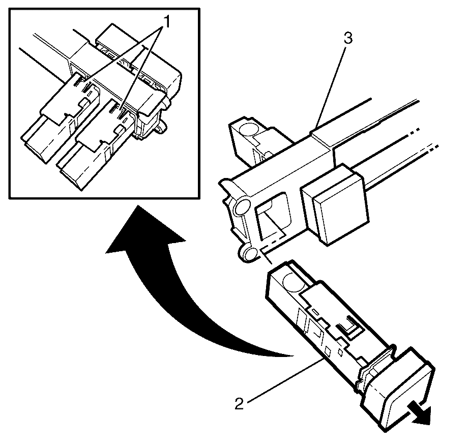
- Using a suitable tool, disengage the auxiliary HVAC enabling switch retainer clips (1) and remove the HVAC enabling switch (2) from the driver information display bezel (3).
Caution: Refer to Battery Disconnect Caution in the Preface section.
Important: The left-hand drive is shown. The right-hand drive is similar.

Installation Procedure
- Install the auxiliary HVAC enabling switch (2) into the driver information display bezel (3), engaging the HVAC enabling switch retainer clips (1).
- Connect the auxiliary HVAC enabling switch electrical connector.
- Install the clock. Refer to Clock Replacement.
- Install the driver information display bezel. Refer to Driver Information Display Bezel Replacement.
- Connect the negative battery cable. Refer to Battery Negative Cable Disconnection and Connection.
- Check the system operation.

