For 1990-2009 cars only
Removal Procedure
- Raise and suitably support the vehicle. Refer to Lifting and Jacking the Vehicle.
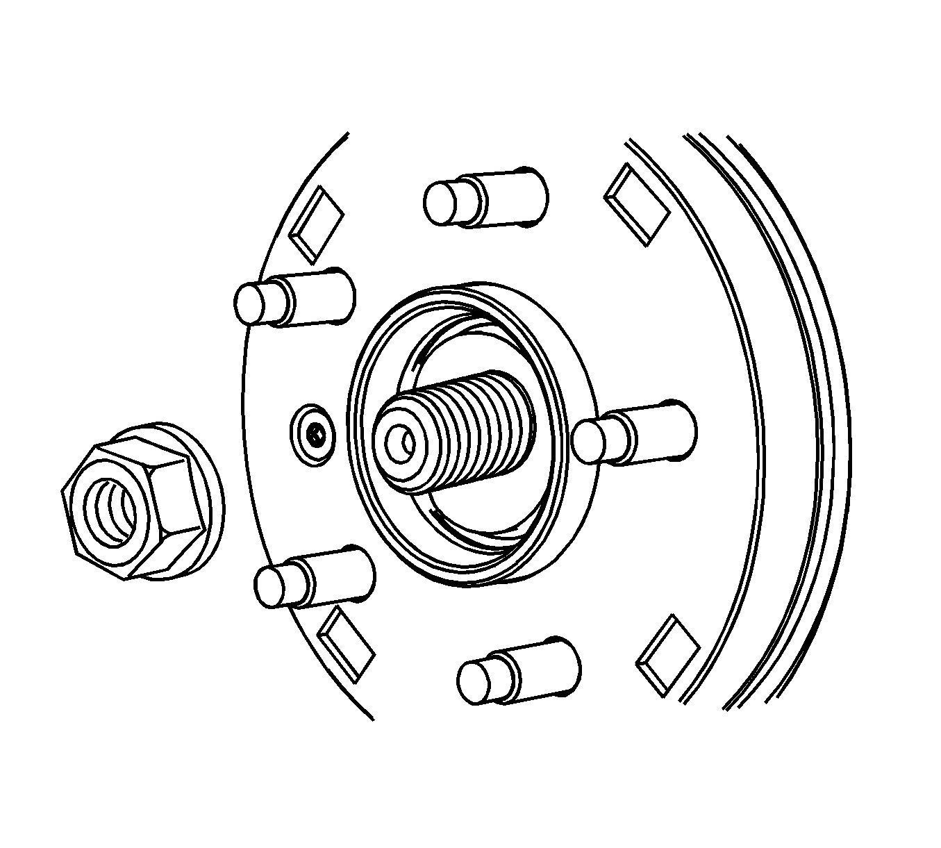
- Remove the rear wheel drive shaft spindle nit.
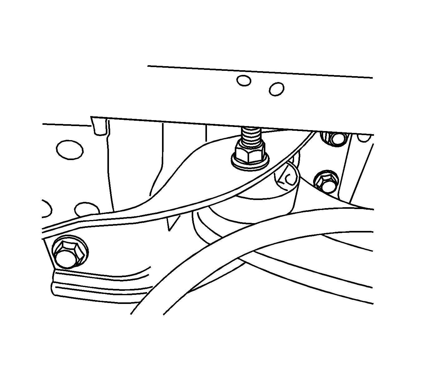
- Remove the trailing arm bracket to underbody bolts.
- Remove the toe link to knuckle nut and bolt.
- Remove the lower control arm to knuckle bolt and nut.
- Loose the knuckle to upper control arm nut and bolt. Do not remove the nut and bolt.
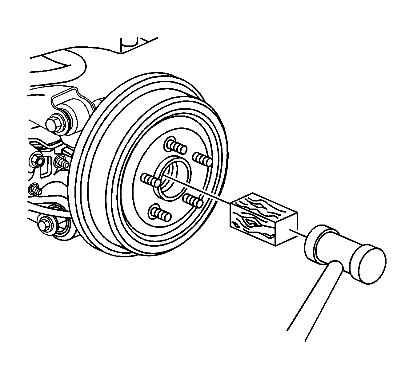
- Place a block of wood against the wheel drive shaft spindle and tap with a hammer to release the spindle from the wheel hub and bearing assembly.
- Rotate the suspension knuckle upward and secure with heavy mechanics wire, or equivalent.
- Remove the wheel drive shaft from the rear drive module (RDM).
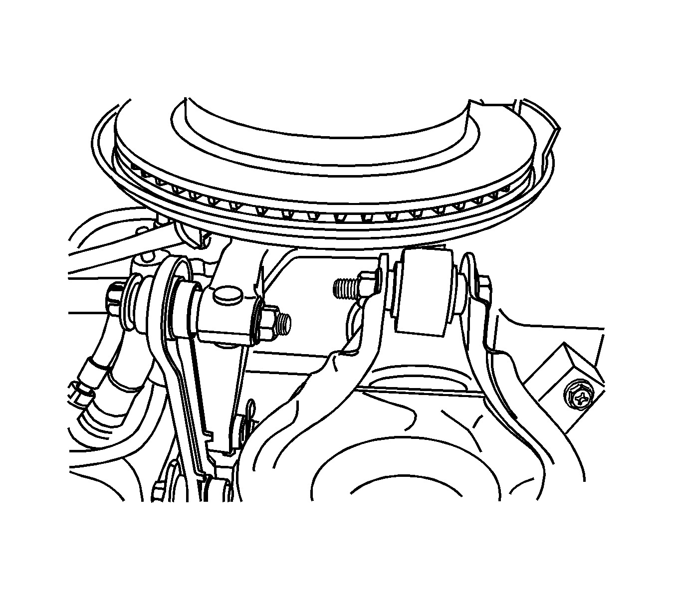
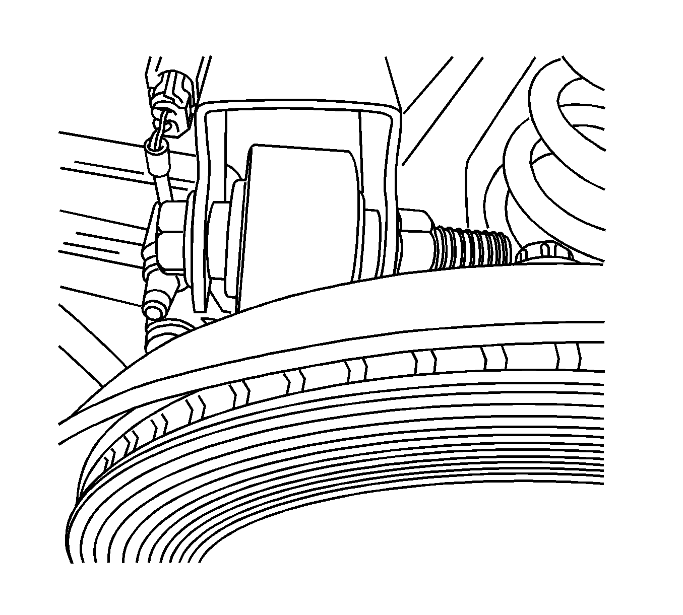
Important: Support the wheel drive shaft while it is disengaged from the wheel hub and bearing assembly in order to avoid damaging the wheel drive shaft seals.
Installation Procedure
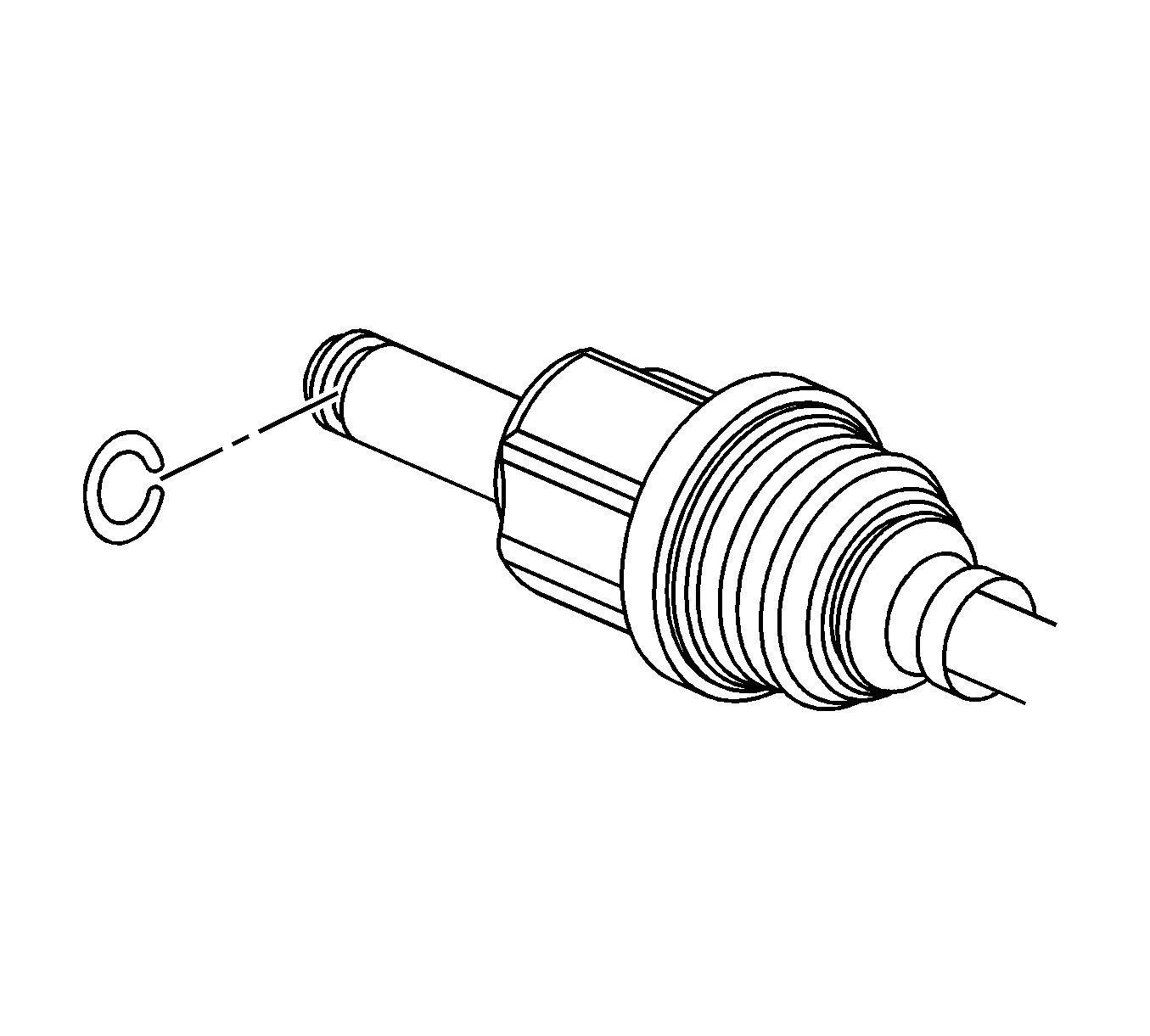
- Install a new wheel drive shaft retaining ring to the inner tripot joint.
- Install the wheel drive shaft to the output shaft of the rear drive module (RDM). Ensure that the tripot joint is fully seated on the output shaft by grasping the tripot joint and attempting to pull free of the output shaft.
- Rotate the suspension knuckle downward while simultaneously guiding the constant velocity (CV) joint spindle to the wheel hub and bearing assembly of the suspension knuckle.
- Hand install a new wheel drive shaft spindle nut.
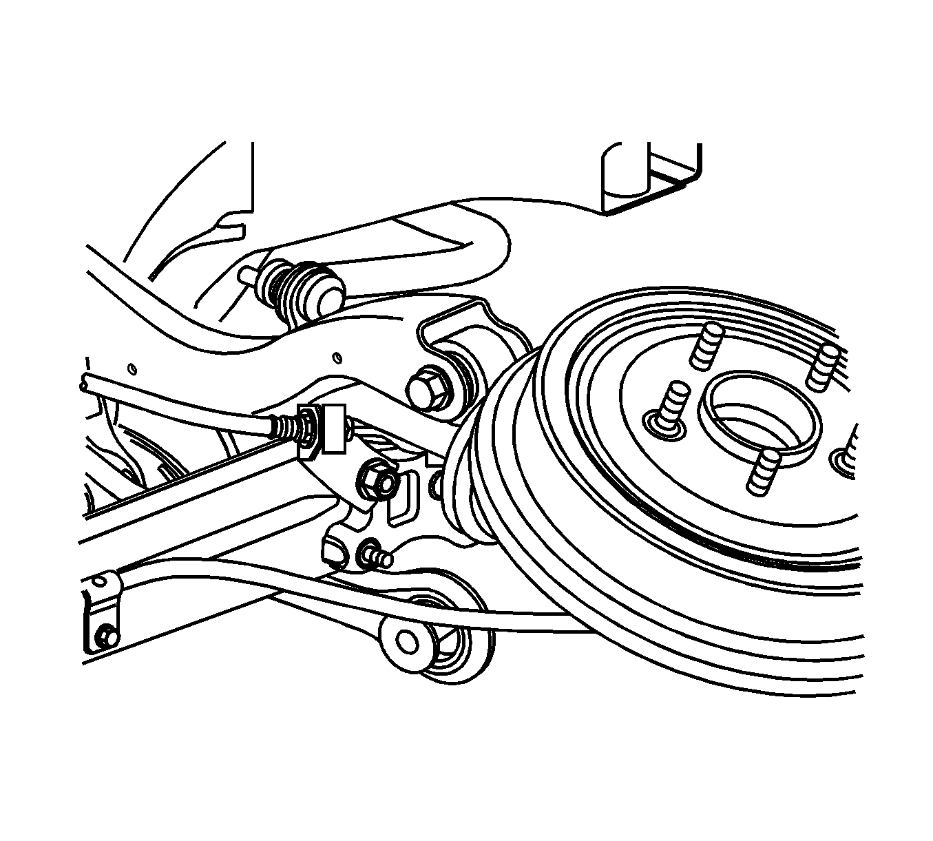
- Install the lower control arm to knuckle bolt and nut.
- Install the trailing arm bracket to underbody bolts.
- Install the toe link to knuckle nut and bolt.
- Check the rear wheel alignment.
Notice: Refer to Fastener Notice in the Preface section.
Tighten
Tighten the lower control arm to knuckle bolt and nut to 160 N·m (118 lb ft).
Tighten
Tighten the trailing arm bracket to underbody bolts to 110 N·m (81 lb ft).
Tighten
Tighten the toe link to knuckle nut and bolt to 160 N·m (118 lb ft).
