Steering Wheel Replacement C100/Long Body
Special Tools
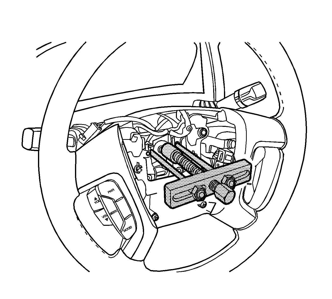
KM-210-A Steering Wheel Puller
Removal Procedure
- Turn the steering wheel to the straight-ahead position.
- Disconnect the negative battery cable and let the vehicle sit for 1 minute. Refer to Battery Negative Cable Disconnection and Connection.
- Remove the supplemental inflatable restraints (SIR) module. Refer to Inflatable Restraint Steering Wheel Module Replacement.
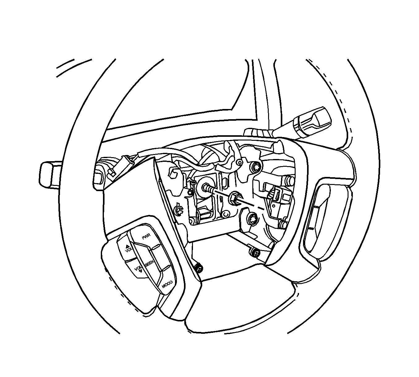
- Remove the steering wheel nut.
- Use paint in order to place match marks on the steering column shaft and on the steering wheel.
- Remove the steering wheel using the KM-210-A puller .
Warning: The sensing and the diagnosis module (SDM) can maintain sufficient voltage to deploy the airbags and pretensioners for up to 1 minute after the ignition has been turned OFF and the fuse has been removed. If the airbags and pretensioners are not disconnected, do not begin service until one minute has been passed after disconnecting power to the SDM. Failure to do so may cause personal injury.


Installation Procedure
- Align the match marks on the steering wheel and the steering column shaft. Turn the signal canceling cam on the wheel to the left.
- Install the steering wheel.
- Install the steering wheel nut and tighten to 41 N·m (30 lb ft).
- Install the SIR module. Refer to Refer to Inflatable Restraint Steering Wheel Module Replacement.
- Connect the negative battery cable. Refer to Battery Negative Cable Disconnection and Connection.

Caution: Refer to Fastener Caution in the Preface section.
Steering Wheel Replacement C105/Short Body
Special Tools
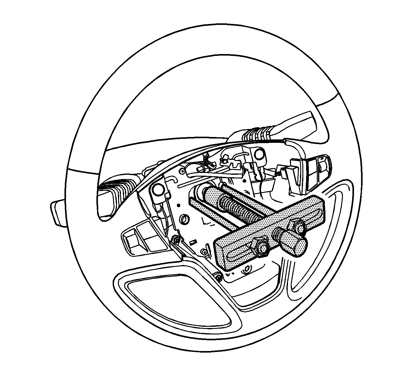
KM-210-A Steering Wheel Puller
Removal Procedure
- Turn the steering wheel to the straight-ahead position.
- Disconnect the negative battery cable and let the vehicle sit for 1 minute. Refer to Battery Negative Cable Disconnection and Connection.
- Remove the SIR module. Refer to Inflatable Restraint Steering Wheel Module Replacement.
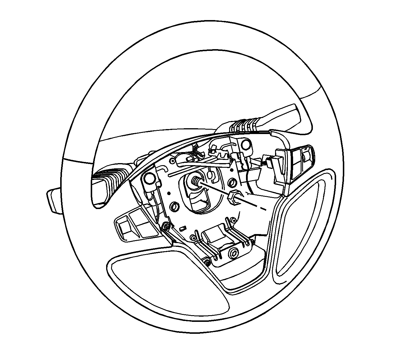
- Remove the steering wheel nut.
- Use paint in order to place match marks on the steering column shaft and on the steering wheel.
- Remove the steering wheel using the KM-210-A puller .
Warning: The sensing and the diagnosis module (SDM) can maintain sufficient voltage to deploy the airbags and pretensioners for up to 1 minute after the ignition has been turned OFF and the fuse has been removed. If the airbags and pretensioners are not disconnected, do not begin service until one minute has been passed after disconnecting power to the SDM. Failure to do so may cause personal injury.


Installation Procedure
- Align the match marks on the steering wheel and the steering column shaft. Turn the signal canceling cam on the wheel to the left.
- Install the steering wheel.
- Install the steering wheel nut and tighten to 41 N·m (30 lb ft).
- Install the SIR module. Refer to Refer to Inflatable Restraint Steering Wheel Module Replacement.
- Connect the negative battery cable. Refer to Battery Negative Cable Disconnection and Connection.

Caution: Refer to Fastener Caution in the Preface section.
