For 1990-2009 cars only
Removal Procedure
- Turn the steering wheel to the straight-ahead position and LOCK the steering column.
- Raise and support the vehicle. Refer to Lifting and Jacking the Vehicle.
- Remove the left front tire and wheel assembly. Refer to Tire and Wheel Removal and Installation.
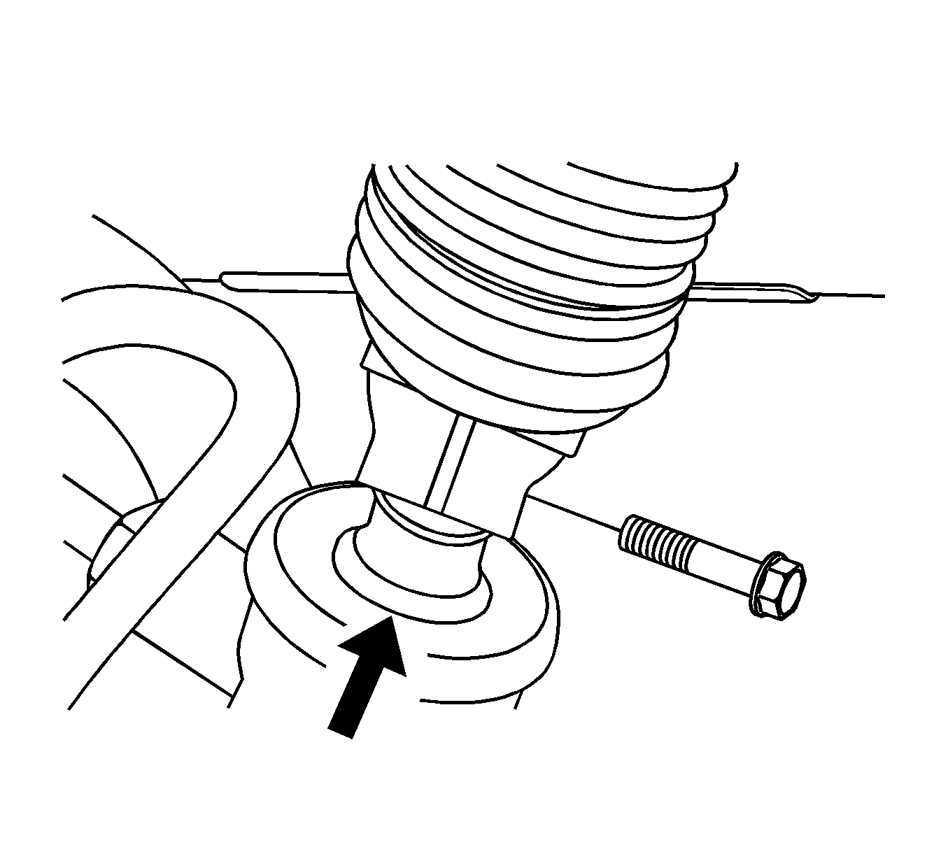
- Place a match mark on the stub shaft housing that lines up with the groove of the intermediate shaft. This mark is for proper alignment during installation.
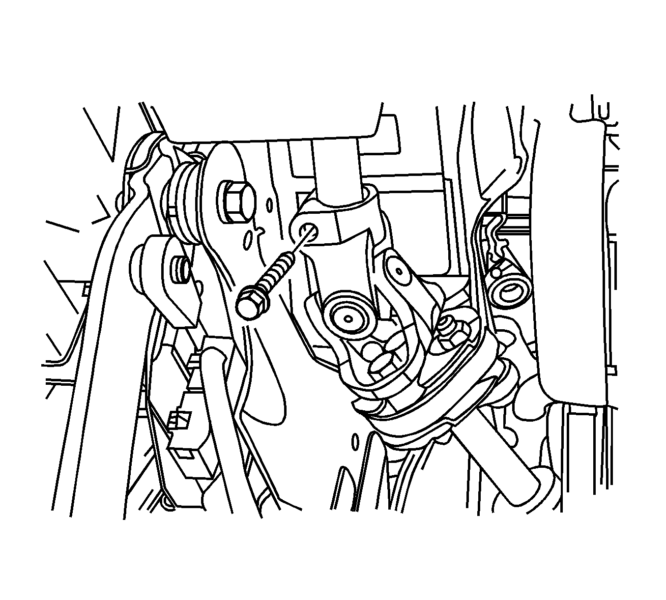
- Remove the lower pinch bolt from the universal joint on the steering gear.
- Remove the upper pinch bolt from the universal joint on the intermediate shaft.
- Remove the intermediate shaft and dash seal.
Caution: Refer to Steering Column in Lock Position Caution in the Preface section.
Note: The left-hand drive model is shown. The right-hand drive model is similar.


Installation Procedure
- Install the intermediate shaft and dash seal into the vehicle.
- Attach the universal joint of the intermediate shaft onto the steering column.
- Install the pinch bolt into the universal joint on the intermediate shaft and tighten to 34 N·m (25 lb ft).
- Attach the intermediate shaft onto the steering gear stub shaft.
- Install the bolt into the lower universal joint on the intermediate shaft and tighten to 34 N·m (25 lb ft).
- Install the left front tire and wheel assembly. Refer to Tire and Wheel Removal and Installation.
- Lower the vehicle.

Note: Ensure the steering wheel is in the straight-ahead position.
Caution: Refer to Fastener Caution in the Preface section.

Note: Align the marks on the intermediate shaft and on the stub shaft.
Note: When installing the lower intermediate shaft pinch bolt, ensure the bolt goes through the universal joint on the side of the stub shaft with the notch. If you have trouble seating the universal joint completely down onto the stub shaft, have an assistant unlock the steering column and rotate the steering wheel slightly while you push down on the universal joint.
