Upper Intake Manifold Cleaning Procedure
- Remove any remaining gasket and/or gasket material from the following:
- Clean the following intake manifold areas in solvent.
| • | Intake manifold gasket sealing areas |
| • | Intake manifold passages |
| • | Brake booster hose passage |
| • | Evaporative emission (EVAP) solenoid passage |
| • | Positive crankcase ventilation (PCV) vacuum hose passages |
| • | Barometric pressure (BARO) sensor passage |
Caution: Refer to Safety Glasses Caution in the Preface section.
- Dry the upper intake manifold and throttle body with compressed air.
Inspection Procedure
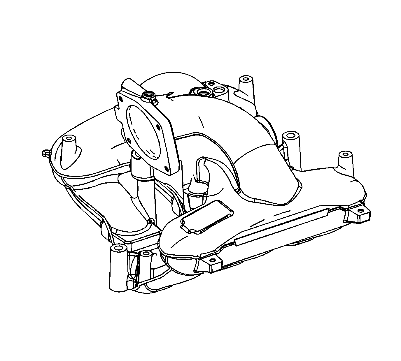
- Inspect the upper intake manifold for the following conditions:
| • | Damage, debris or restrictions to the BARO sensor mounting port |
| • | Damage, debris or restrictions to the brake vacuum booster hose port |
| • | Damage to the throttle body bolt holes |
| • | Damage, debris or restrictions to the PCV system hose ports |
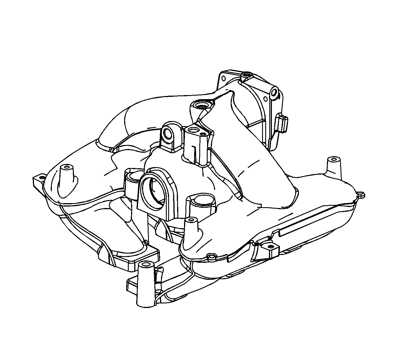
- Inspect the upper intake manifold for the following conditions:
| • | Damage to the intake manifold bolt bosses |
| • | Damage to the EVAP purge solenoid mounting boss |
| • | Damage, debris or restrictions to the EVAP purge solenoid port |
| • | Damage, debris or restrictions in the vacuum passage |
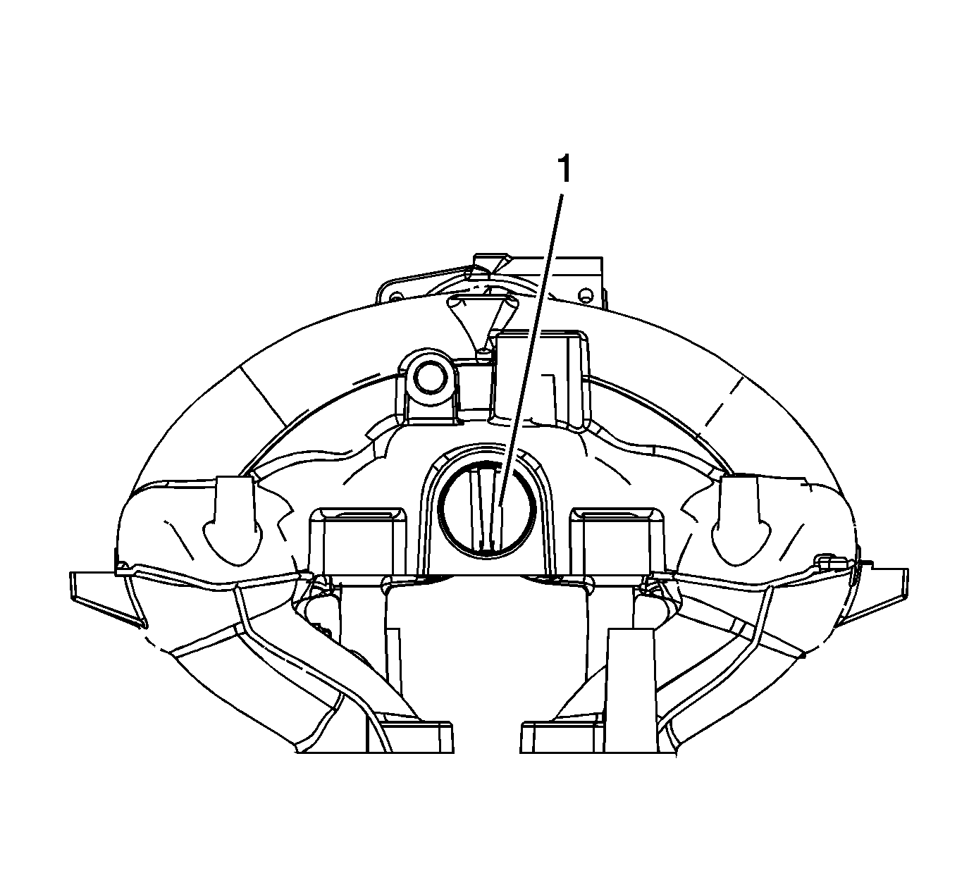
- Inspect the upper intake manifold for the following conditions:
| • | Damage, debris or restrictions to the intake manifold opening cover port (1) |
| • | Damage to the intake manifold opening cover |
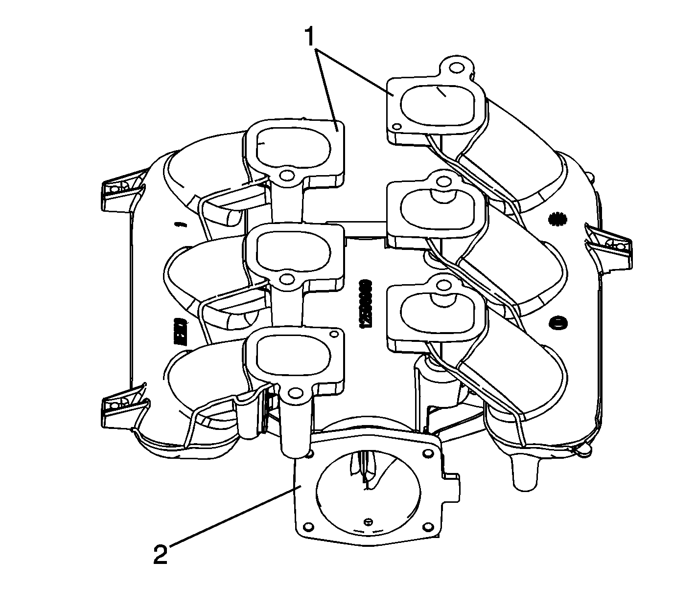
- Inspect the upper intake manifold for the following conditions:
| • | Gouges or damage to the upper intake manifold sealing surfaces (1) |
| • | Damage to the gasket sealing surface (2) for the throttle body |
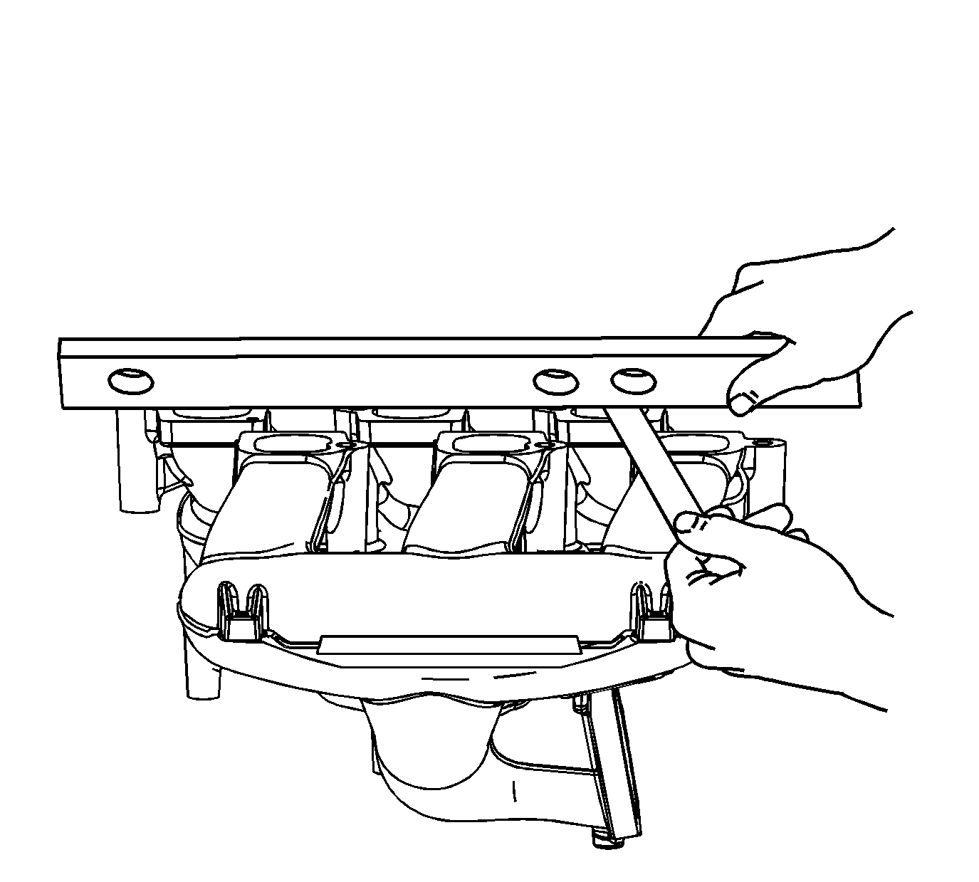
- Inspect the upper intake manifold sealing surface for
warpage.
| 5.1. | Locate a straight edge across the upper-to-lower intake manifold sealing surface. |
| 5.2. | Insert a feeler gage between the upper intake manifold and the straight edge. An upper intake manifold with warpage in excess of 0.05 mm (0.020 in) must be replaced. |
- Repair or replace the upper intake manifold as necessary.
Lower Intake Manifold Cleaning Procedure
- Remove any remaining gasket and/or gasket material from the following:
| • | Upper-to-lower intake manifold sealing surface |
| • | Cylinder head-to-lower intake manifold sealing surface |
- Clean the following intake manifold areas in solvent.
| • | Intake manifold gasket sealing surfaces |
| • | Intake manifold passages |
Caution: Refer to Safety Glasses Caution in the Preface section.
- Dry the intake manifold with compressed air.
Inspection Procedure
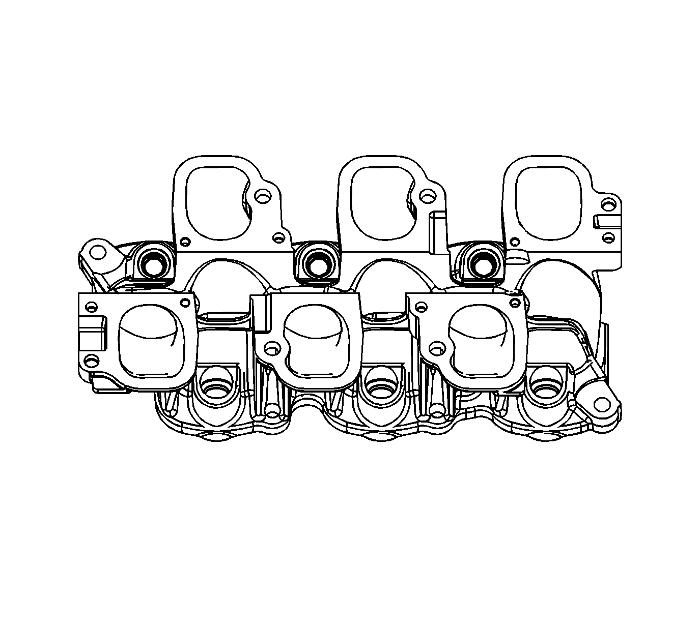
- Inspect the lower intake manifold for the following conditions:
| • | Damage, debris or restrictions to the lower intake manifold ports |
| • | Damage to the fuel rail mounting bolt holes |
| • | Damage to the fuel rail |
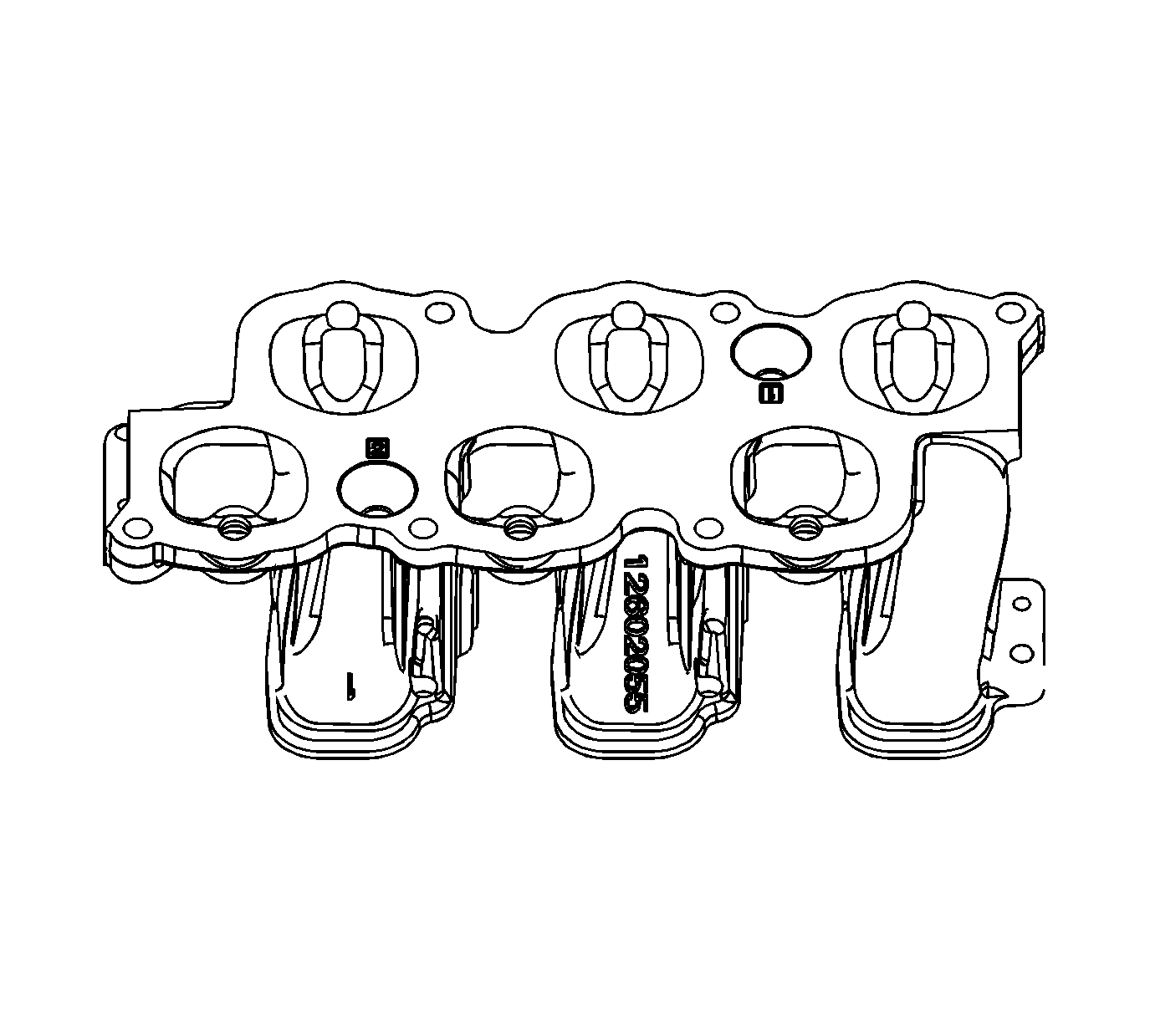
- Inspect the lower intake manifold for the following conditions:
| • | Gouges or damage to the intake manifold sealing surfaces |
| • | Damage to the lower intake manifold bolt bosses |
| • | Damage to the fuel injector ports |
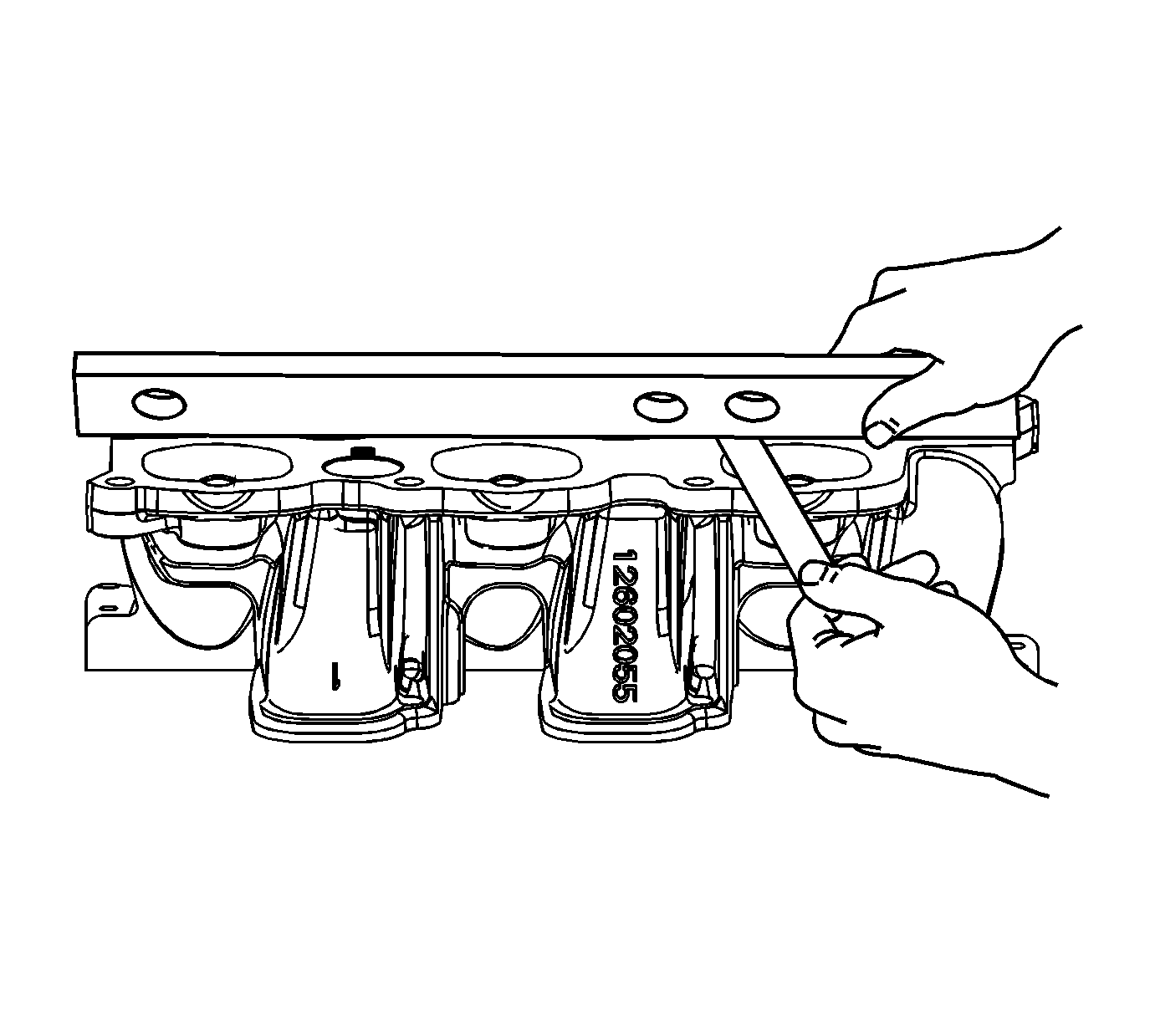
- Inspect the lower intake manifold sealing surfaces for
warpage.
| 3.1. | Locate a straight edge across the lower intake manifold sealing surfaces. |
| 3.2. | Insert a feeler gage between the lower intake manifold and the straight edge. A lower intake manifold with warpage in excess of 0.5 mm (0.020 in) must be replaced. |
- Repair or replace the lower intake manifold as necessary.
Intake Manifold Cleaning and Inspection LY7
Upper Intake Manifold Cleaning Procedure
- Remove any remaining gasket and/or gasket material from the following:
- Clean the following intake manifold areas in solvent.
| • | Intake manifold gasket sealing areas |
| • | Intake manifold passages |
| • | Brake booster hose passage |
| • | Evaporative emission (EVAP) solenoid passage |
| • | Positive crankcase ventilation (PCV) vacuum hose passages |
| • | Barometric pressure (BARO) sensor passage |
Warning: Refer to Safety Glasses Warning in the Preface section.
- Dry the upper intake manifold and throttle body with compressed air.
Inspection Procedure

- Inspect the upper intake manifold for
the following conditions:
| • | Damage, debris or restrictions to the BARO sensor mounting port |
| • | Damage, debris or restrictions to the brake vacuum booster hose port |
| • | Damage to the throttle body bolt holes |
| • | Damage, debris or restrictions to the PCV system hose ports |

- Inspect the upper intake manifold for
the following conditions:
| • | Damage to the intake manifold bolt bosses |
| • | Damage to the EVAP purge solenoid mounting boss |
| • | Damage, debris or restrictions to the EVAP purge solenoid port |
| • | Damage, debris or restrictions in the vacuum passage |

- Inspect the upper intake manifold for
the following conditions:
| • | Damage, debris or restrictions to the intake manifold opening cover port (1) |
| • | Damage to the intake manifold opening cover |

- Inspect the upper intake manifold for
the following conditions:
| • | Gouges or damage to the upper intake manifold sealing surfaces (1) |
| • | Damage to the gasket sealing surface (2) for the throttle body |

- Inspect the upper intake manifold sealing
surface for warpage.
| 5.1. | Locate a straight edge across the upper-to-lower intake manifold sealing surface. |
| 5.2. | Insert a feeler gage between the upper intake manifold and the straight edge. An upper intake manifold with warpage in excess of 0.05 mm (0.020 in) must be replaced. |
- Repair or replace the upper intake manifold as necessary.
Lower Intake Manifold Cleaning Procedure
- Remove any remaining gasket and/or gasket material from the following:
| • | Upper-to-lower intake manifold sealing surface |
| • | Cylinder head-to-lower intake manifold sealing surface |
- Clean the following intake manifold areas in solvent.
| • | Intake manifold gasket sealing surfaces |
| • | Intake manifold passages |
Warning: Refer to Safety Glasses Warning in the Preface section.
- Dry the intake manifold with compressed air.
Inspection Procedure

- Inspect the lower intake manifold for
the following conditions:
| • | Damage, debris or restrictions to the lower intake manifold ports |
| • | Damage to the fuel rail mounting bolt holes |
| • | Damage to the fuel rail |

- Inspect the lower intake manifold for
the following conditions:
| • | Gouges or damage to the intake manifold sealing surfaces |
| • | Damage to the lower intake manifold bolt bosses |
| • | Damage to the fuel injector ports |

- Inspect the lower intake manifold sealing
surfaces for warpage.
| 3.1. | Locate a straight edge across the lower intake manifold sealing surfaces. |
| 3.2. | Insert a feeler gage between the lower intake manifold and the straight edge. A lower intake manifold with warpage in excess of 0.5 mm (0.020 in) must be replaced. |
- Repair or replace the lower intake manifold as necessary.
Intake Manifold Cleaning and Inspection LCS
Lower Intake Manifold Assemble Procedure
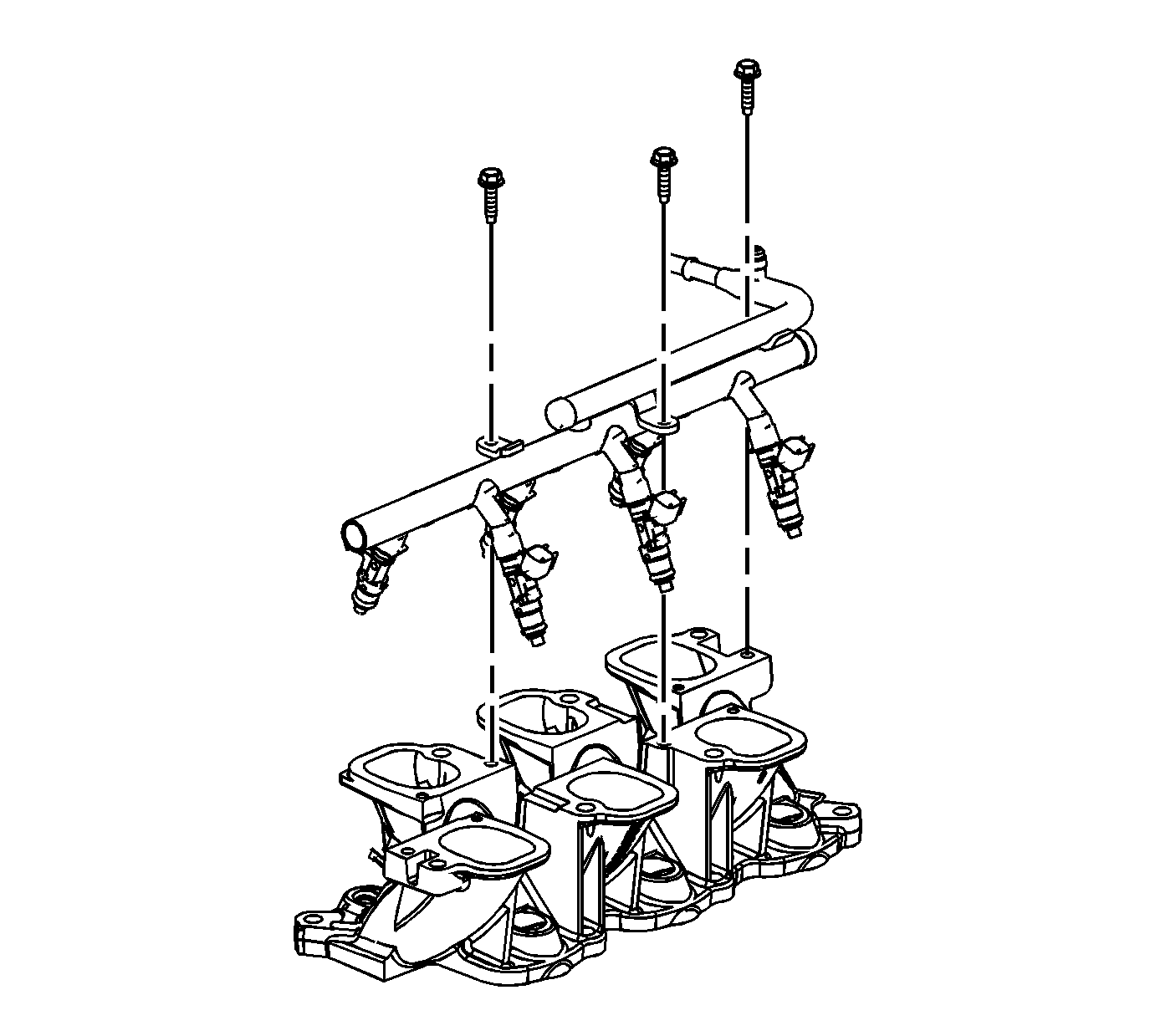
- Install the fuel injector rail.
Caution: Refer to Fastener Caution in the Preface section.
- Install the fuel injector rail bolts and tighten to
10 N·m (89 lb in).
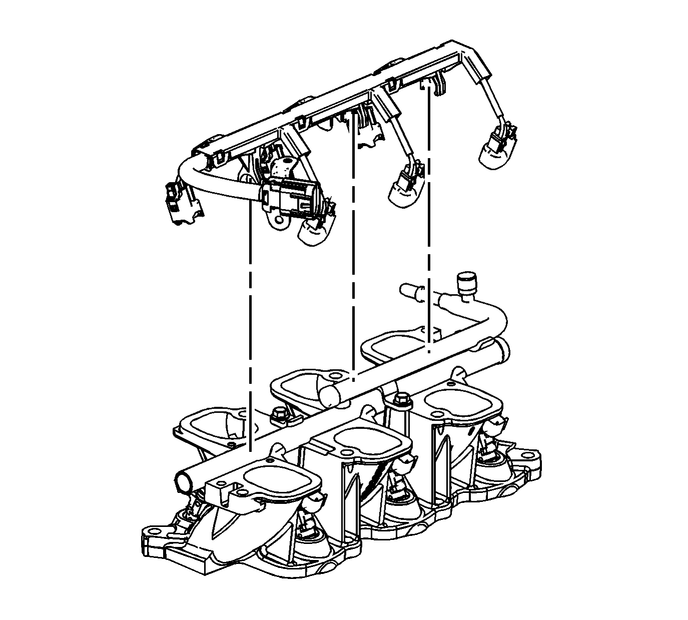
- Install the fuel injector wiring harness connector.
Upper Intake Manifold Assemble Procedure
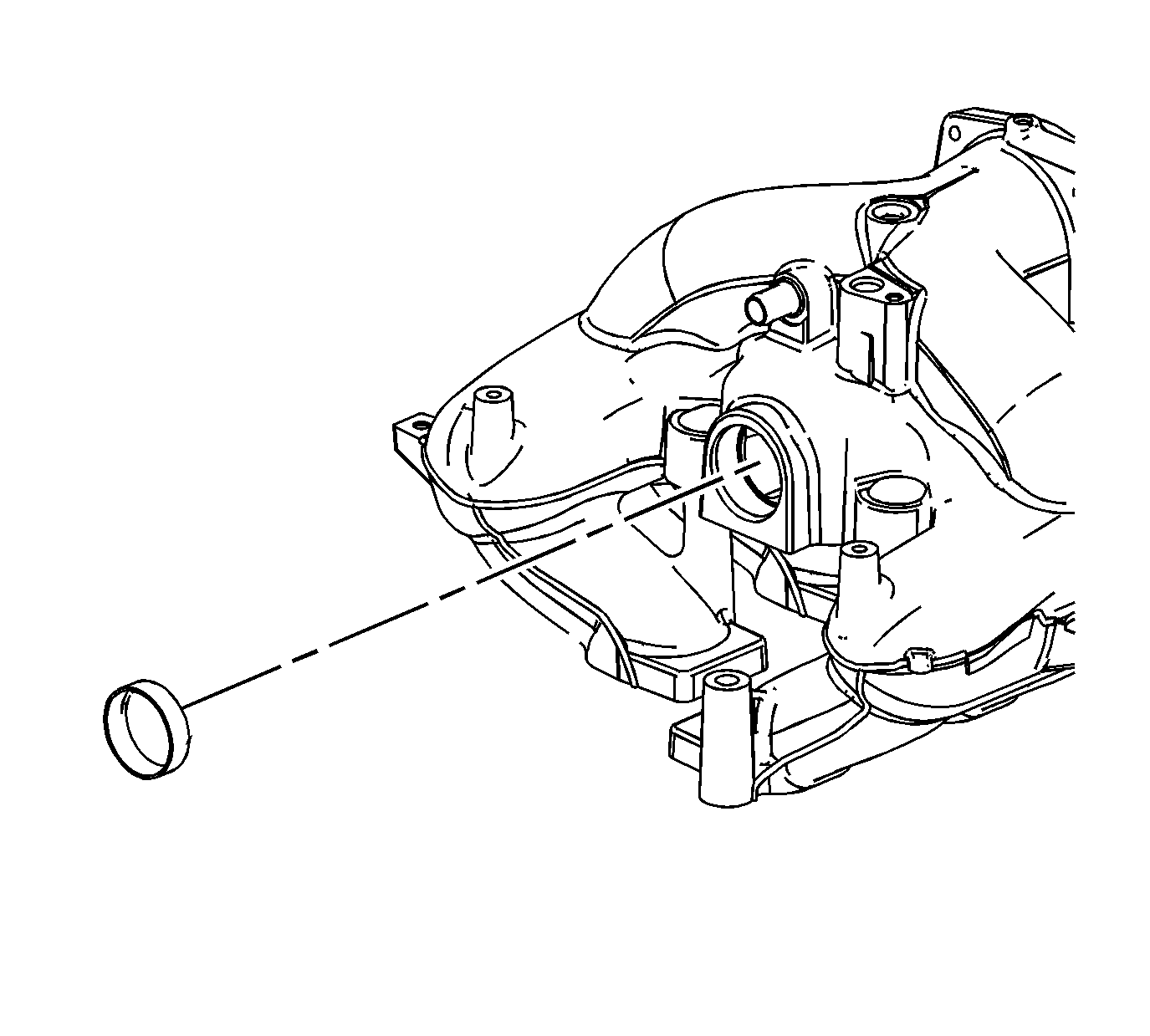
- Install the intake manifold opening
cover.
- Install the intake manifold opening cover bolts and tighten to
10 N·m (89 lb in).
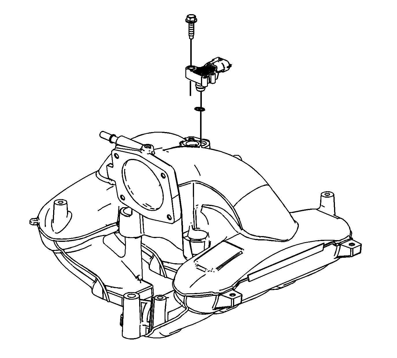
- Install the barometric pressure (BARO)
sensor.
- Install the BARO sensor bolt and tighten to
10 N·m (89 lb in).
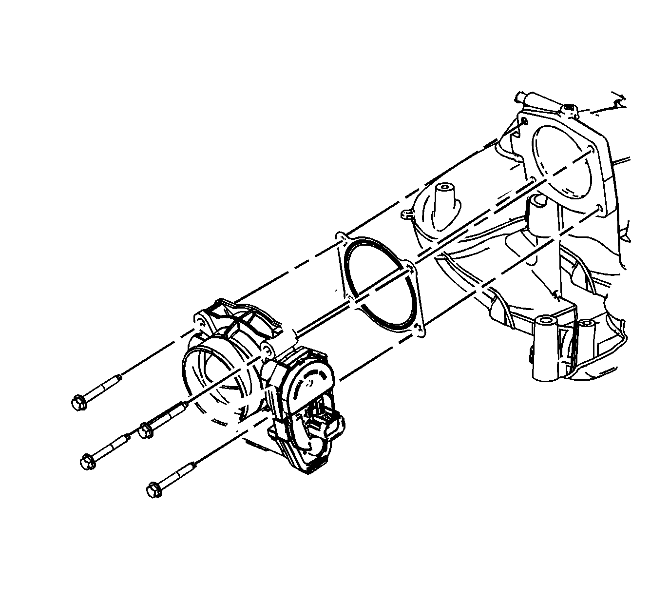
- Install the NEW throttle body gasket.
- Install the throttle body.
- Install the throttle body bolts and tighten to
10 N·m (89 lb in).
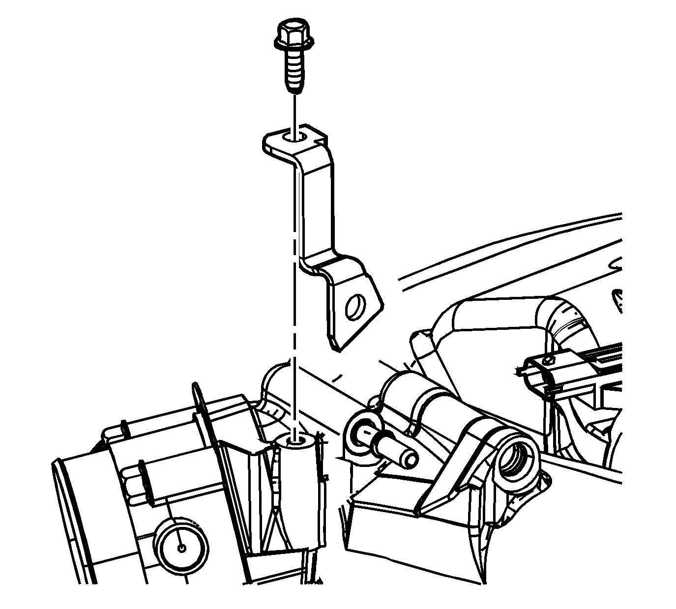
- Install the fuel rail support bracket.
- Install the fuel rail support bracket bolt and tighten to
10 N·m (89 lb in).
Upper to Lower Intake Manifold Assemble Procedure
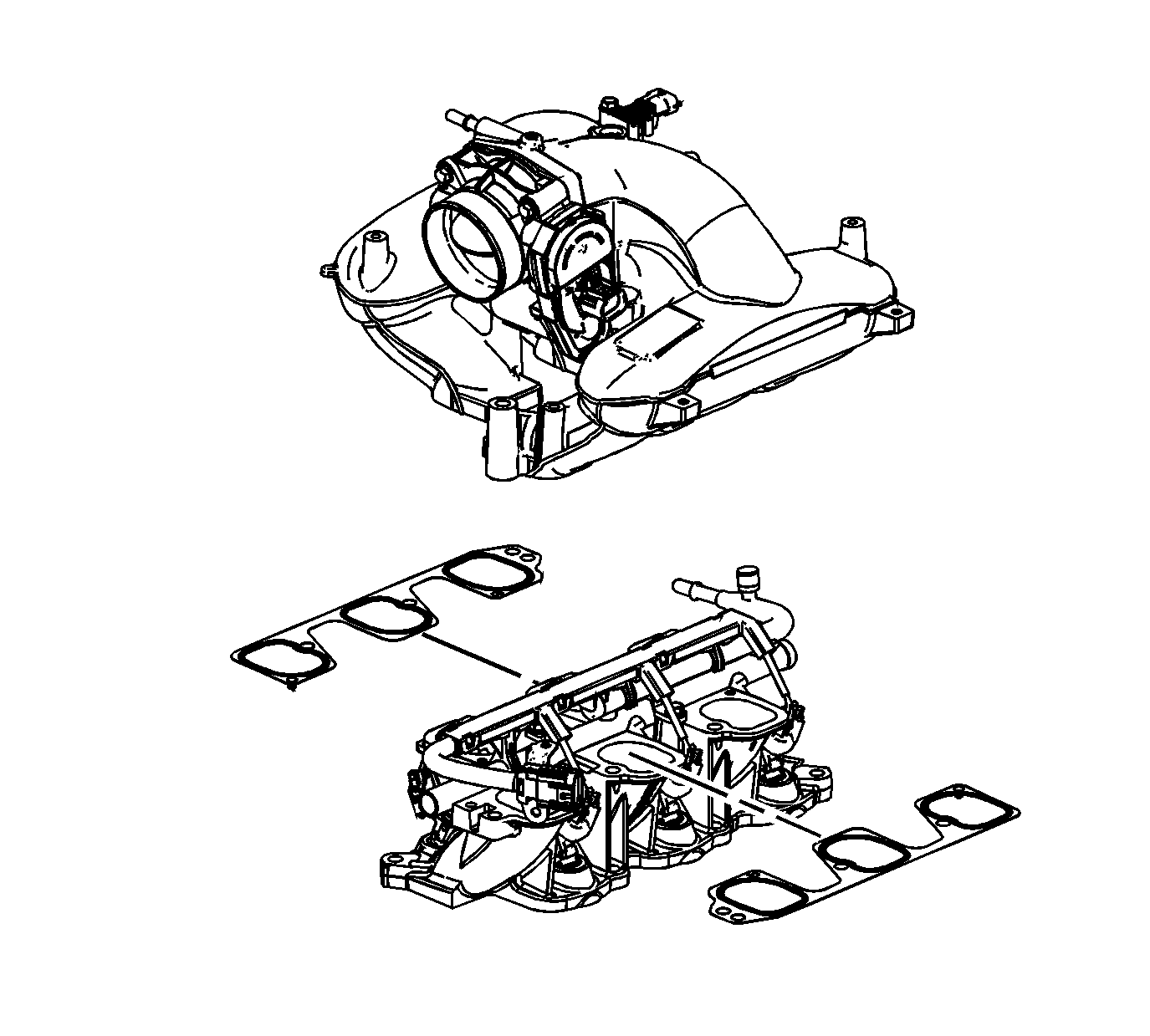
Note: Do not reuse the upper-to-lower intake manifold gasket and the intake manifold-to-cylinder head sealing gaskets.
- Install the NEW upper-to-lower intake manifold gaskets.
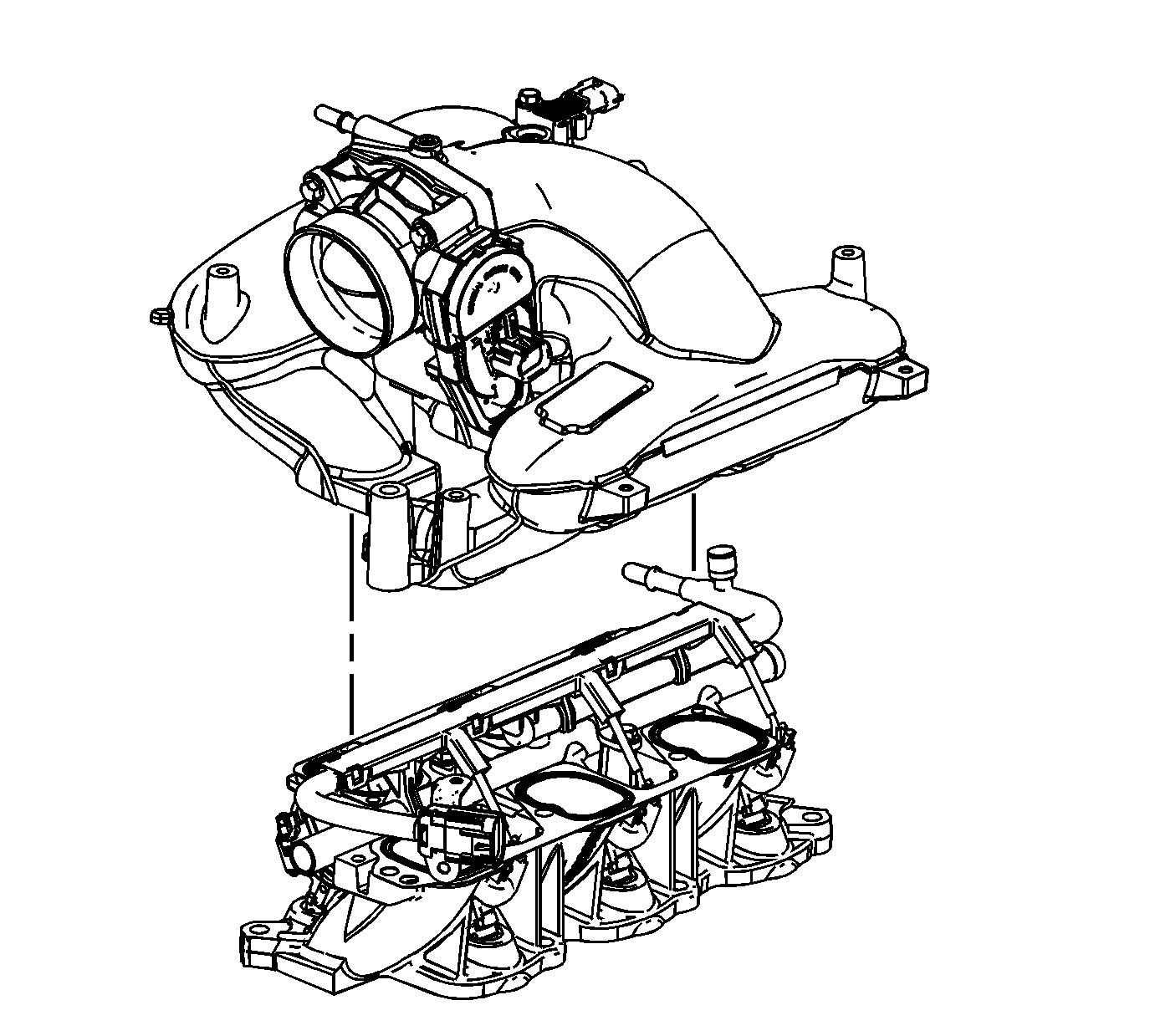
- Install the upper intake manifold to
the lower intake manifold.
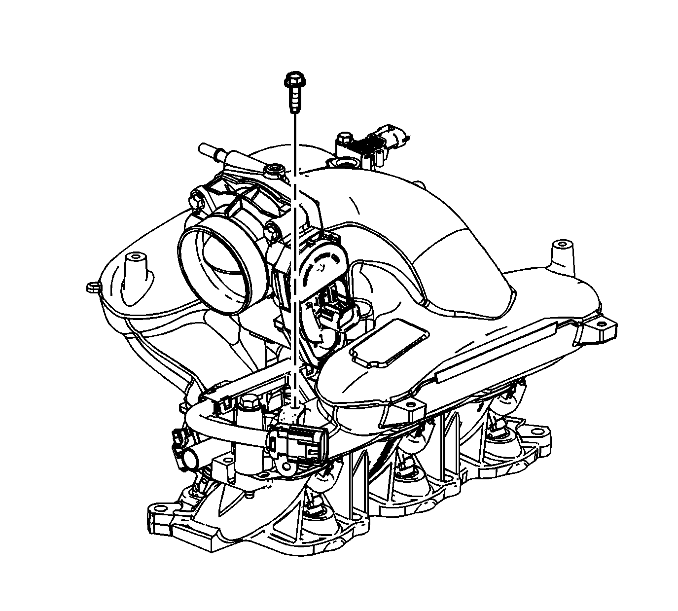
- Install the fuel injector wiring harness
bracket bolts to the upper intake manifold and tighten to
10 N·m (89 lb in).
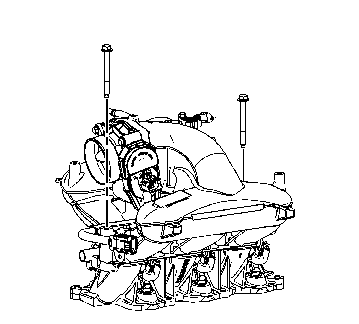
- Install the upper-to-lower intake manifold
bolts and tighten to
23 N·m (17 lb ft).


