For 1990-2009 cars only
Exhaust Manifold Heat Shield Replacement - Right Side LY7
Removal Procedure
- Remove the fuel injector sight shield. Refer to Fuel Injector Sight Shield Replacement.
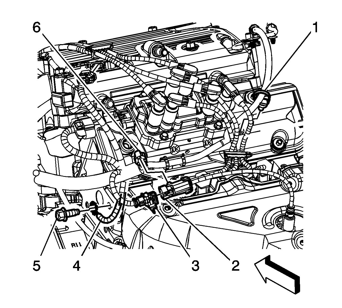
- Disconnect the engine wiring harness electrical connector (3) from the heated oxygen sensor (HO2S) electrical connector (4).
- Remove the HO2S electrical connector retainer (5) from the retainer clip.
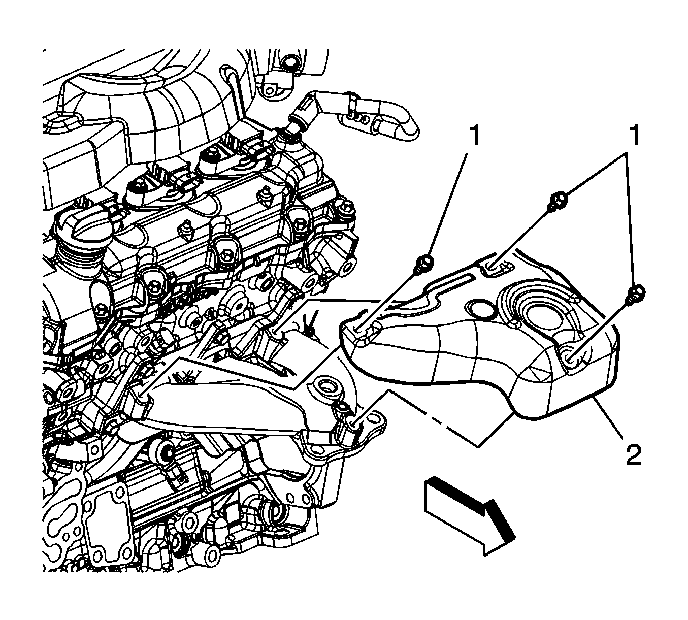
- Remove the exhaust manifold heat shield bolts (1).
- Remove the exhaust manifold heat shield (2).


Installation Procedure
- Install the exhaust manifold heat shield (2).
- Install the exhaust manifold heat shield bolts (1).
- Connect the engine harness electrical connector (3) to the HO2S electrical connector (4).
- Install the HO2S electrical connector retainer (5) to the retainer clip.
- Install the fuel injector sight shield. Refer to Fuel Injector Sight Shield Replacement.
Notice: Refer to Fastener Notice in the Preface section.

Tighten
Tighten the bolts 22 N·m (16 lb ft).

Exhaust Manifold Heat Shield Replacement - Right Side LZ4
Removal Procedure
- Remove the intake manifold cover. Refer to Intake Manifold Cover Replacement.
- Remove the connector position assurance (CPA) retainer.
- Disconnect the engine wiring harness electrical connector (3) from the heated oxygen sensor (HO2S) electrical connector (2).
- Remove the HO2S electrical connector rosebud clip from the engine wiring harness retainer strap (6).
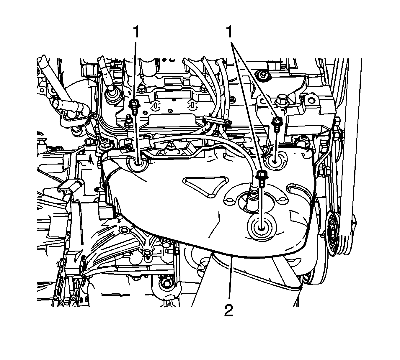
- Remove the exhaust manifold heat shield bolts (1).
- Remove the exhaust manifold heat shield (2).


Installation Procedure
- Install the exhaust manifold heat shield (2).
- Install the exhaust manifold heat shield bolts (1).
- Connect the engine harness electrical connector (3) to the HO2S electrical connector (2).
- Install the CPA retainer.
- Install the HO2S electrical connector rosebud clip to the engine wiring harness retaining strap (6).
- Install the intake manifold cover. Refer to Intake Manifold Cover Replacement.
Notice: Refer to Fastener Notice in the Preface section.

Tighten
Tighten the bolts 22 N·m (16 lb ft).

Exhaust Manifold Heat Shield Replacement - Right Side LY7 or LCS
Removal Procedure
- Remove the fuel injector sight shield. Refer to Fuel Injector Sight Shield Replacement.
- Disconnect the engine wiring harness electrical connector (3) from the heated oxygen sensor (HO2S) electrical connector (4).
- Remove the HO2S electrical connector retainer (5) from the retainer clip.
- Remove the exhaust manifold heat shield bolts (1).
- Remove the exhaust manifold heat shield (2).


Installation Procedure
- Install the exhaust manifold heat shield (2).
- Install the exhaust manifold heat shield bolts (1) and tighten to 22 N·m (16 lb ft).
- Connect the engine harness electrical connector (3) to the HO2S electrical connector (4).
- Install the HO2S electrical connector retainer (5) to the retainer clip.
- Install the fuel injector sight shield. Refer to Fuel Injector Sight Shield Replacement.
Caution: Refer to Fastener Caution in the Preface section.


Exhaust Manifold Heat Shield Replacement - Right Side LZ4
Removal Procedure
- Remove the intake manifold cover. Refer to Intake Manifold Cover Replacement.
- Remove the connector position assurance (CPA) retainer.
- Disconnect the engine wiring harness electrical connector (3) from the heated oxygen sensor (HO2S) electrical connector (2).
- Remove the HO2S electrical connector rosebud clip from the engine wiring harness retainer strap (6).
- Remove the exhaust manifold heat shield bolts (1).
- Remove the exhaust manifold heat shield (2).


Installation Procedure
- Install the exhaust manifold heat shield (2).
- Install the exhaust manifold heat shield bolts (1) and tighten to 22 N·m (16 lb ft).
- Connect the engine harness electrical connector (3) to the HO2S electrical connector (2).
- Install the CPA retainer.
- Install the HO2S electrical connector rosebud clip to the engine wiring harness retaining strap (6).
- Install the intake manifold cover. Refer to Intake Manifold Cover Replacement.

Caution: Refer to Fastener Caution in the Preface section.

