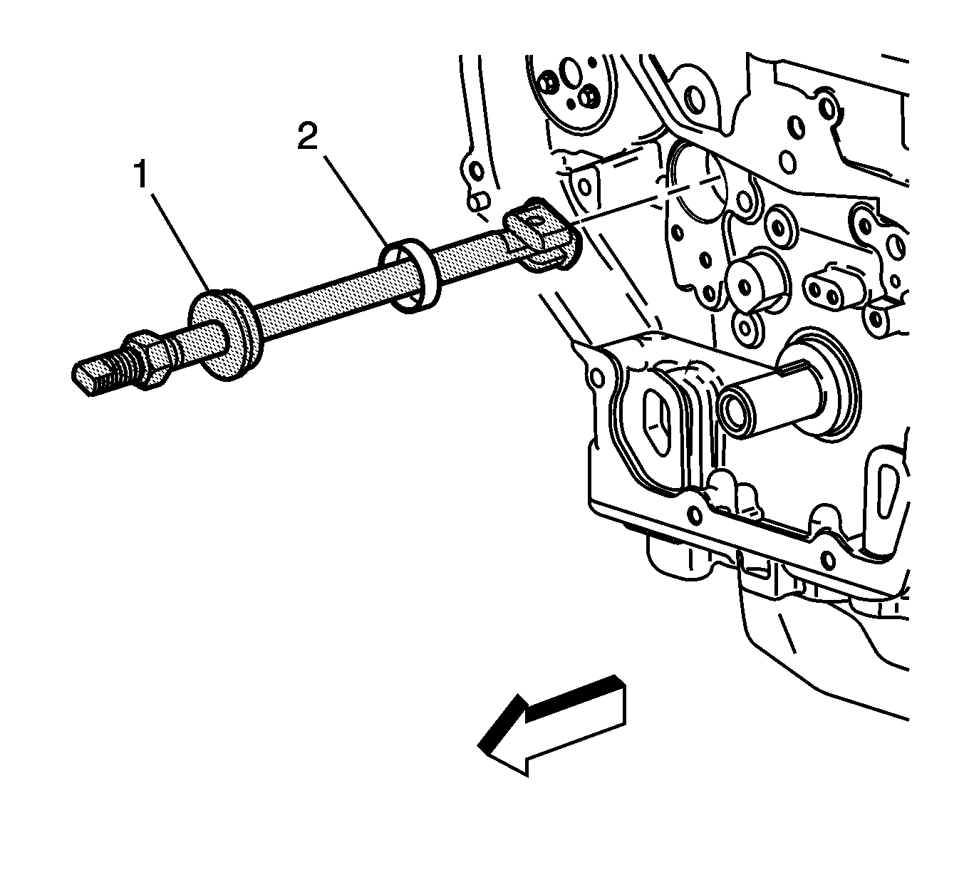
Tools Required
J 43650 Balancer Shaft Bearing Remover and Installer
- Remove the balance shaft bearing carrier bolts.
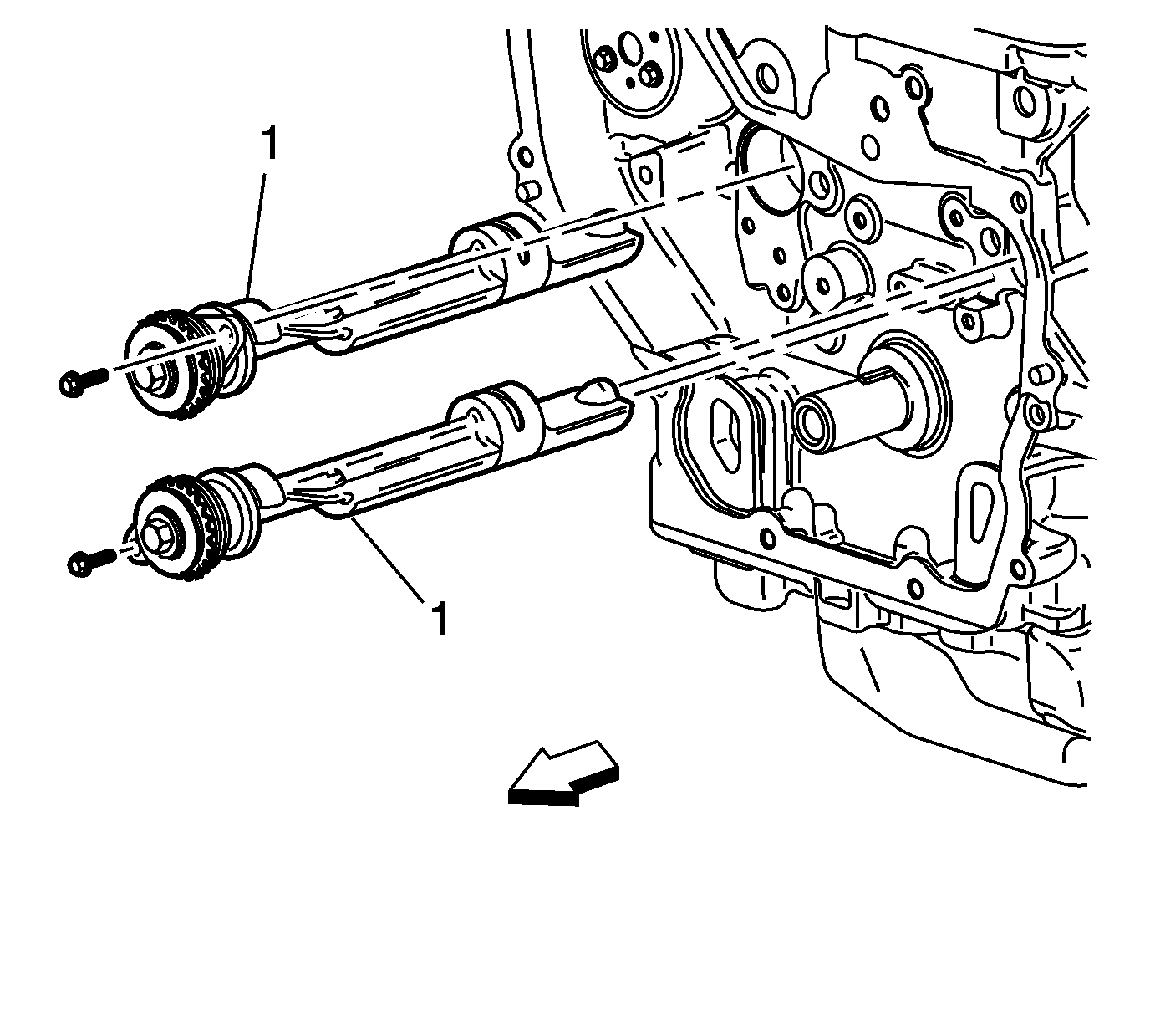
- Remove the balance shaft assemblies.
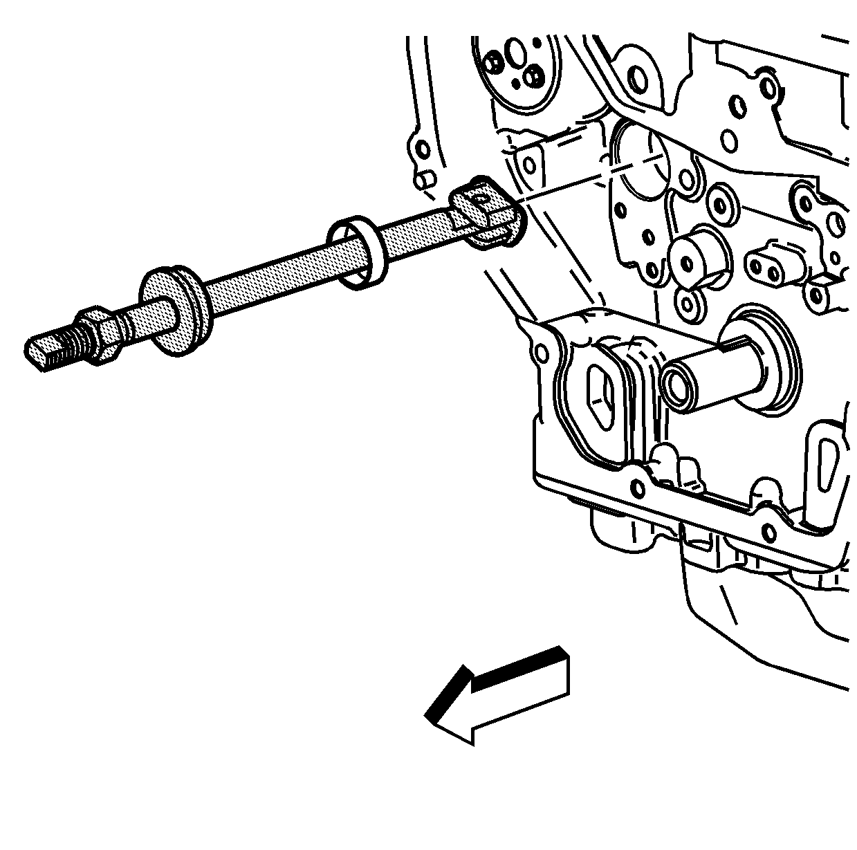
- Install the J 43650 into the balance shaft hole. Insert the tool with the foot parallel to the shaft.
- When the J 43650 is inserted in the block turn the J 43650 so that the foot becomes perpendicular to the shaft.
- Center the foot of the J 43650 on the balance shaft bushing.
- Once the J 43650 is centered on the balance shaft bushing, then insert the centering guide into the front balance shaft bore and tighten the nut with an appropriate wrench.
- Tighten the nut on the J 43650 until the tension releases. When the tension releases, remove the J 43650 and the balance shaft bushing.
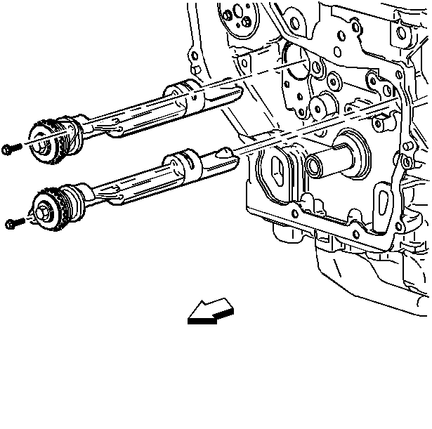
Important:
• It is possible to install the intake side balance shaft into the exhaust
side and vice versa. Please use care not to install the balance shafts into
the wrong bores. Engine vibration will result. • Do not remove the bolt holding the sprocket.
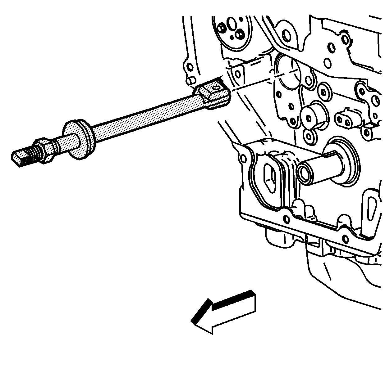
Notice: Proper centering of the tool is required on the balance shaft bushing. If the tool is not properly centered then damage to the bearing bore and block will occur.
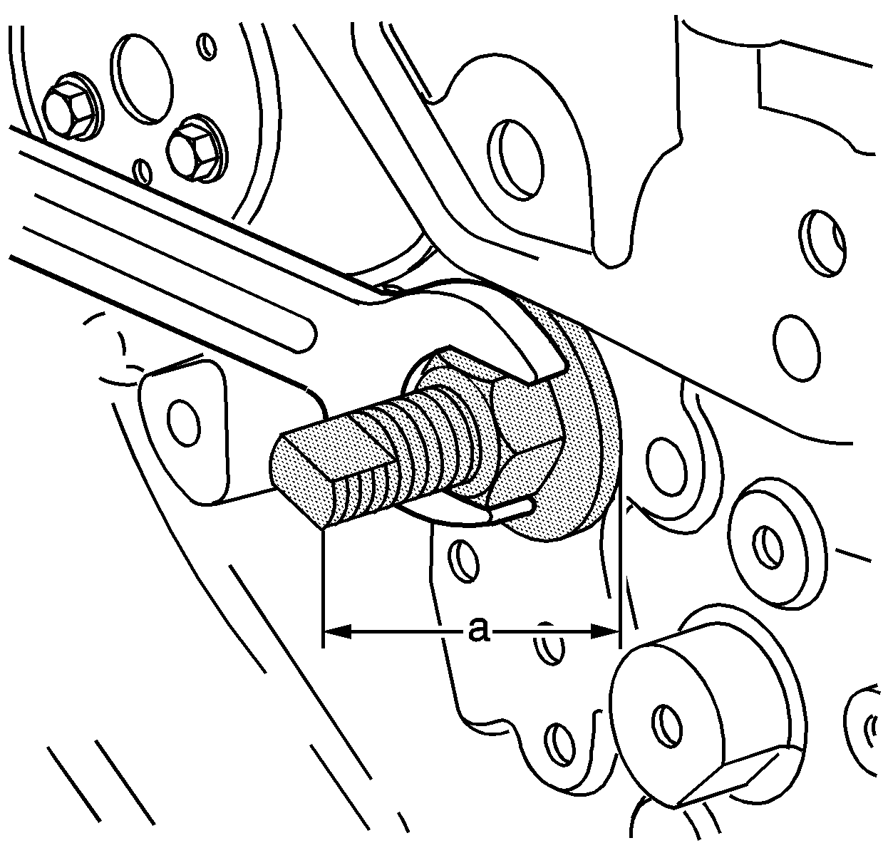
When the J 43650 is properly installed, before removing the bushing, the end of the tool should be 116 mm (4.6 in) (a) from the block face.
If the J 43650 is less than approximately 114 mm (4.5 in) (a), recheck the tool alignment.
Special Tools
EN-43650 Balancer Shaft Bearing Remover and Installer
For equivalent regional tools, refer to Special Tools.
- Remove the balance shaft bearing carrier bolts.
- Remove the balance shaft assemblies (1).
- Install the EN-43650 remover (1) into the balance shaft hole. Insert the tool with the foot parallel to the shaft.
- When the EN-43650 remover (1) is inserted in the block turn the EN-43650 remover so that the foot becomes perpendicular to the shaft.
- Center the foot of the EN-43650 remover on the balance shaft bushing.
- Once the EN-43650 remover is centered on the balance shaft bushing, then insert the centering guide into the front balance shaft bore and tighten the nut with an appropriate wrench (2).
- Tighten the nut on the EN-43650 remover (1) until the tension releases. When the tension releases, remove the EN-43650 remover and the balance shaft bushing (2).
Note:
• It is possible to install the intake side balance shaft into the exhaust side and vice versa. Please use care not to install the balance shafts into the wrong bores. Engine vibration will result. • Do not remove the bolt holding the sprocket.
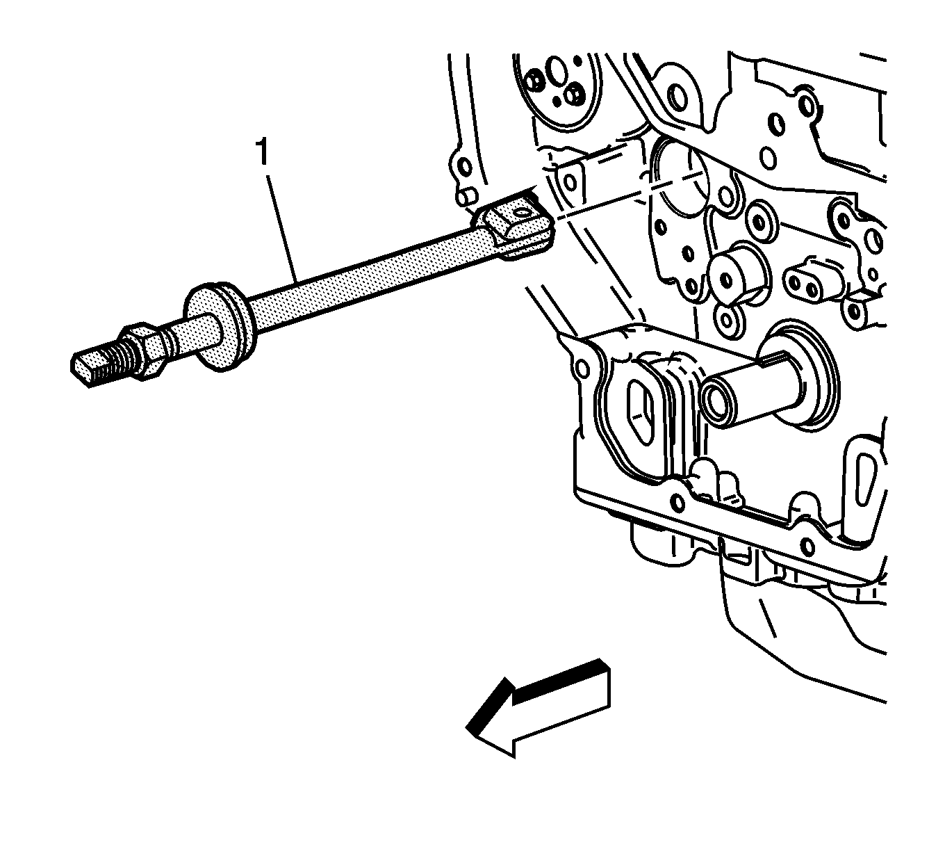
Caution: Proper centering of the tool is required on the balance shaft bushing. If the tool is not properly centered then damage to the bearing bore and block will occur.
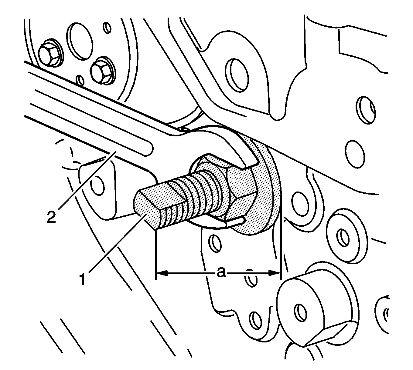
When the EN-43650 remover is properly installed, before removing the bushing, the end of the tool should be 116 mm (4.6 in) (a) from the block face.
If the EN-43650 remover is less than approximately 114 mm (4.5 in) (a), recheck the tool alignment.
