For 1990-2009 cars only
Removal Procedure
- Raise and support the vehicle. Refer to Lifting and Jacking the Vehicle .
- Remove the rear tire and wheel assembly. Refer to Tire and Wheel Removal and Installation .
- Remove the stabilizer shaft link. Refer to Stabilizer Shaft Link Replacement .
- Position a jackstand underneath the lower control arm.
- Raise the jackstand slightly to compress the coil spring.
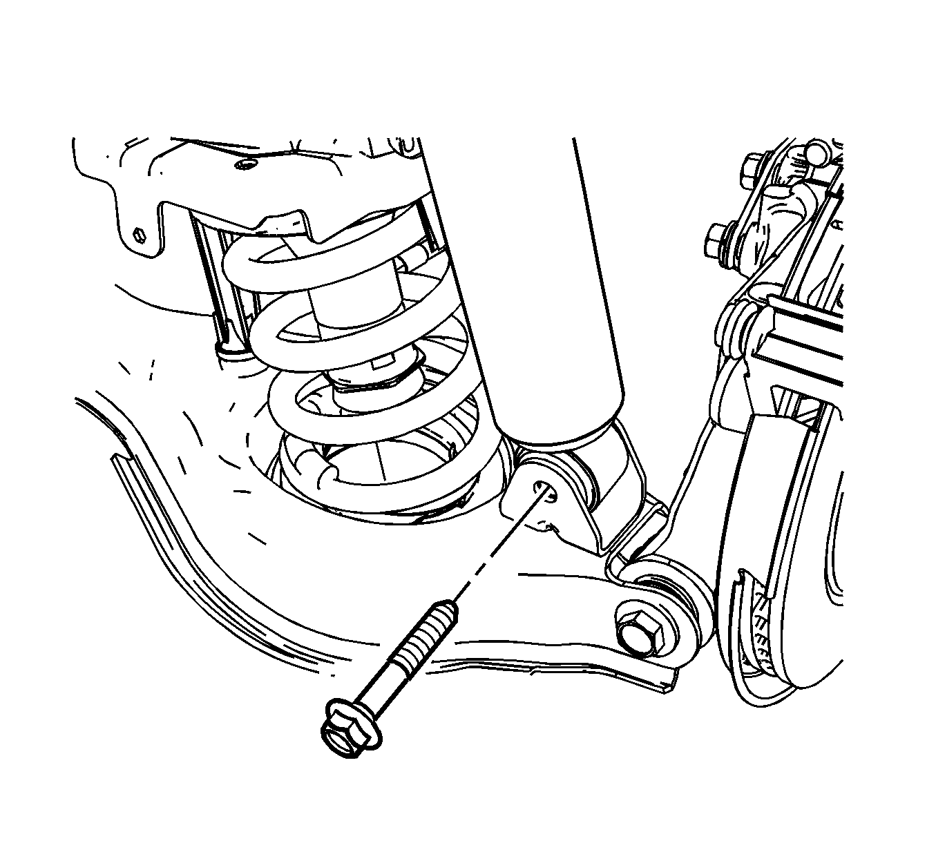
- Remove the lower shock bolt and nut.
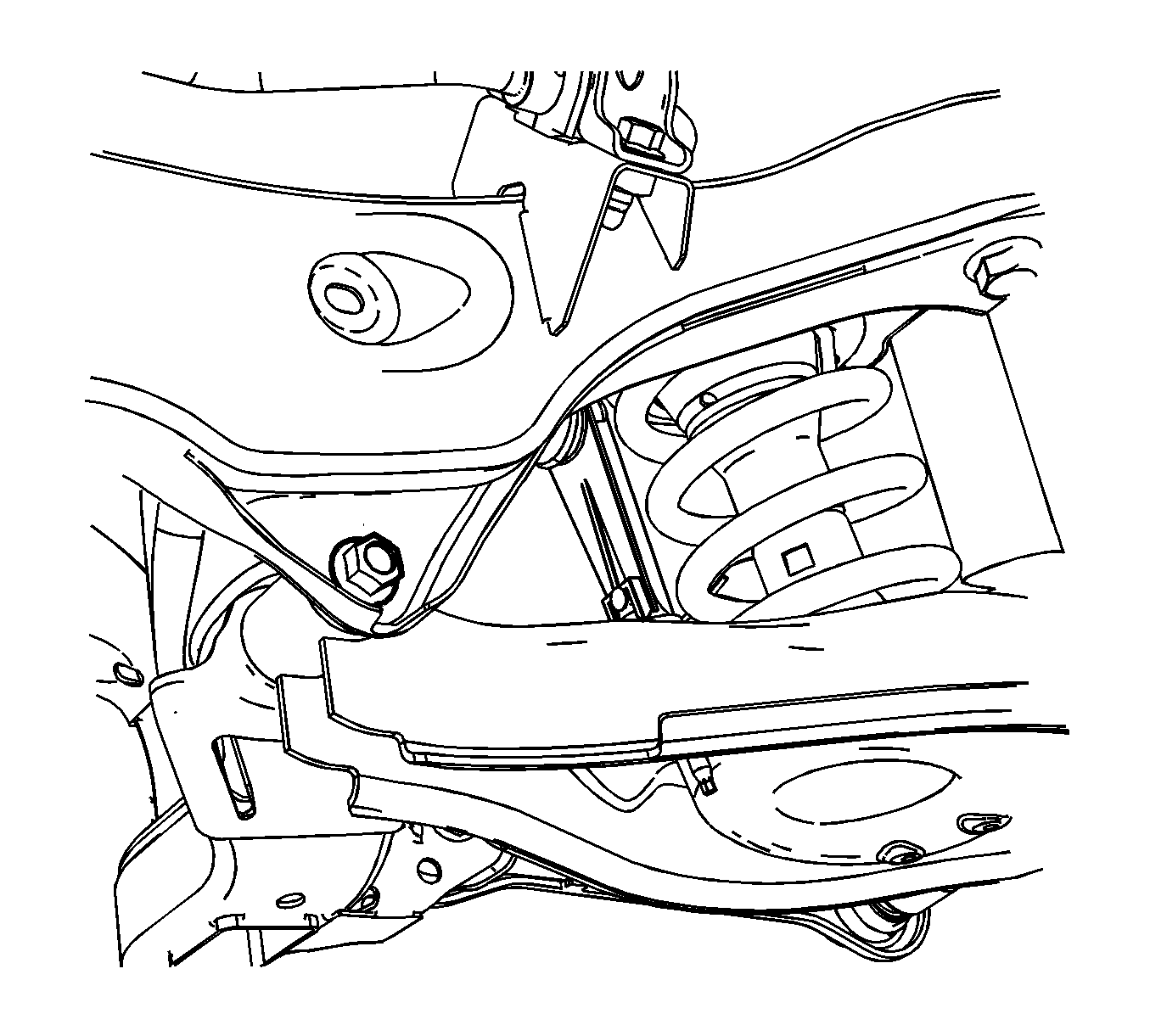
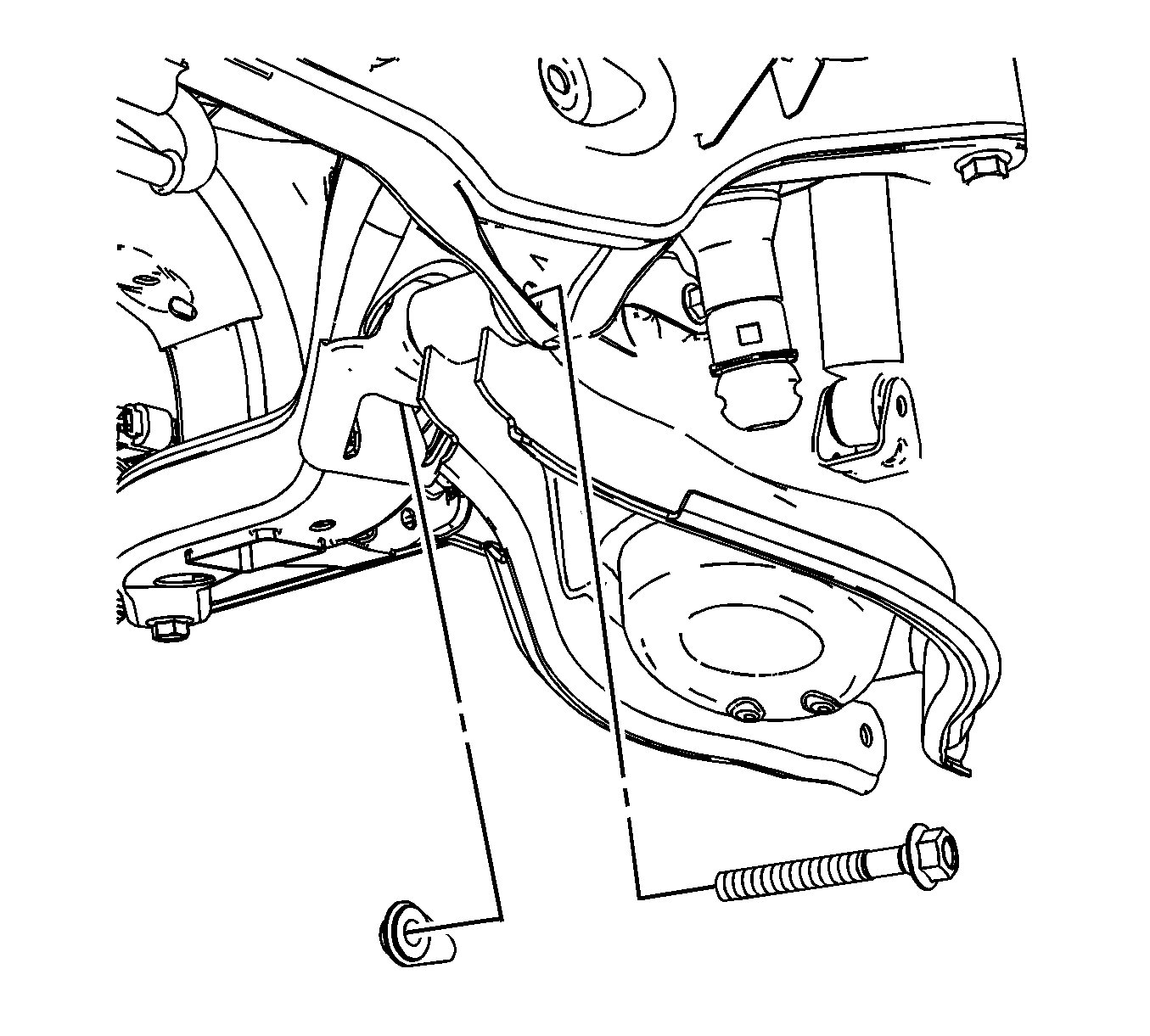
- Loosen the lower control arm to support frame nut and bolt.
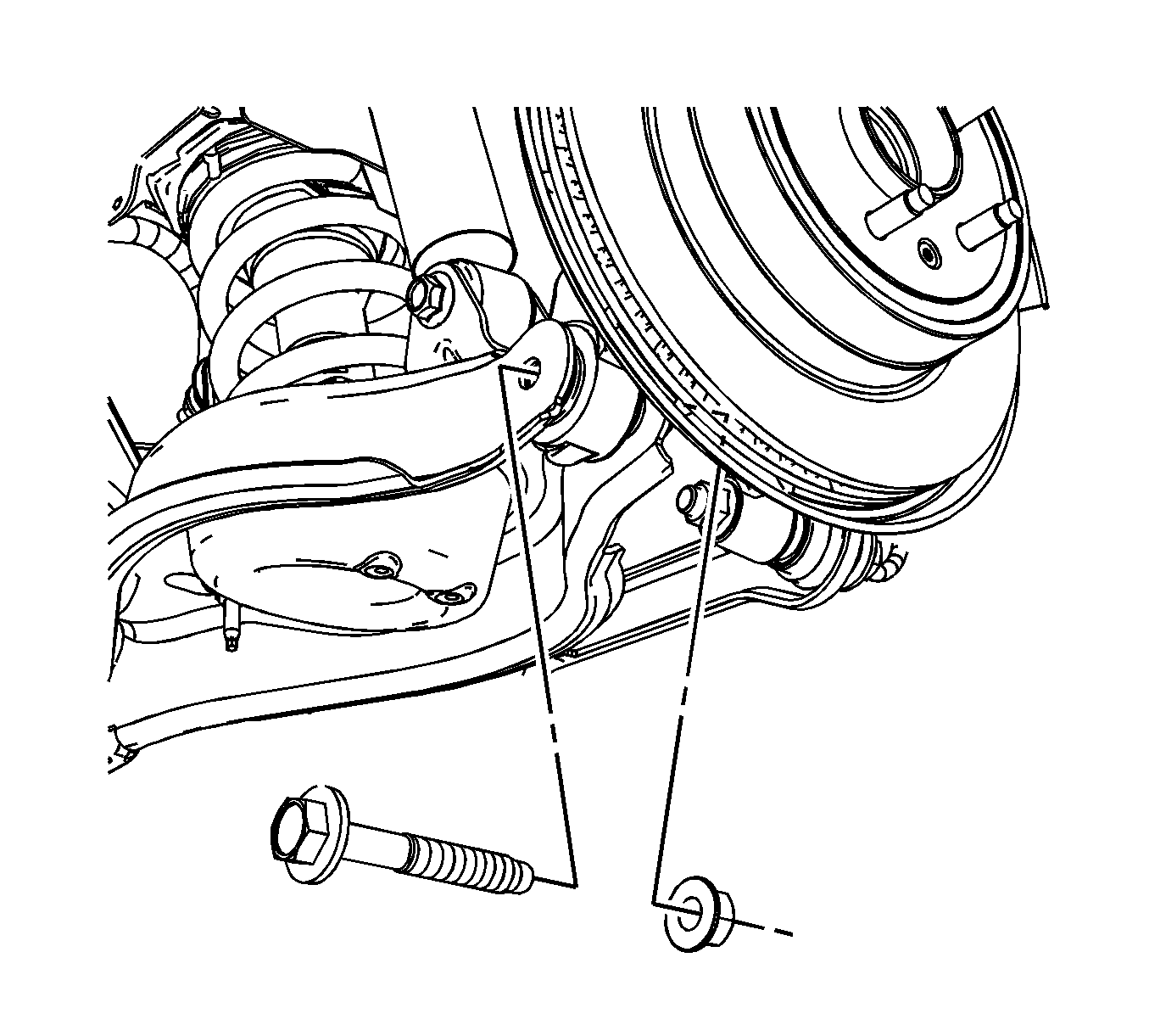
- Remove the lower control arm to knuckle nut and bolt.
- Slowly lower the control arm in order to unload the coil spring.
- Remove the coil spring.
- Remove the jackstand.
- Remove the lower control arm to support frame nut and bolt.
- Remove the lower control arm.


Installation Procedure
- Inspect the coil spring upper and lower insulators, if damage exists replace the insulators. Refer to Coil Spring Insulators Replacement .
- Position the lower control arm to the support frame and loosely install the nut and bolt.
- Position the jackstand under the lower control arm.
- Position the spring with the rubber insulators into the vehicle.
- Raise the jackstand to compress the spring.
- Position the lower control arm to the knuckle and install the nut and bolt.
- Tighten the lower control arm to support nut and bolt.
- Install the shock to the lower control arm nut and bolt.
- Remove the jackstand from under the vehicle.
- Install the stabilizer shaft link. Refer to Stabilizer Shaft Link Replacement .
- Install the rear tire and wheel assembly. Refer to Tire and Wheel Removal and Installation .
- Lower the vehicle.
- Check the rear alignment. Refer to Wheel Alignment Measurement .

Notice: Refer to Fastener Notice in the Preface section.

Tighten
Tighten the lower control arm to knuckle bolt and nut to 160 N·m (118 lb ft).

Tighten
Tighten the bolt to 110 N·m (81 lb ft).

Tighten
Tighten the lower shock bolt and nut to 110 N·m (81 lb ft).
Removal Procedure
- Raise and support the vehicle. Refer to Lifting and Jacking the Vehicle.
- Remove the rear tire and wheel assembly. Refer to Tire and Wheel Removal and Installation.
- Remove the stabilizer shaft link. Refer to Stabilizer Shaft Link Replacement.
- Position a jackstand underneath the lower control arm.
- Raise the jackstand slightly to compress the coil spring.
- Remove the lower shock bolt and nut.
- Loosen the lower control arm to support frame nut and bolt.
- Remove the lower control arm to knuckle nut and bolt.
- Slowly lower the control arm in order to unload the coil spring.
- Remove the coil spring.
- Remove the jackstand.
- Remove the lower control arm to support frame nut and bolt.
- Remove the lower control arm.


Installation Procedure
- Inspect the coil spring upper and lower insulators, if damage exists replace the insulators. Refer to Rear Spring Insulator Replacement.
- Position the lower control arm to the support frame and loosely install the nut and bolt.
- Position the jackstand under the lower control arm.
- Position the spring with the rubber insulators into the vehicle.
- Raise the jackstand to compress the spring.
- Position the lower control arm to the knuckle and install the nut and bolt. Tighten the nut/bolt to 160 N·m (118 lb ft)
- Tighten the lower control arm to support nut and bolt to 110 N·m (81 lb ft).
- Install the shock to the lower control arm nut and bolt and tighten to 110 N·m (81 lb ft).
- Remove the jackstand from under the vehicle.
- Install the stabilizer shaft link. Refer to Stabilizer Shaft Link Replacement.
- Install the rear tire and wheel assembly. Refer to Tire and Wheel Removal and Installation.
- Lower the vehicle.
- Check the rear alignment. Refer to Wheel Alignment Measurement.

Caution: Refer to Fastener Caution in the Preface section.


