Caution: Refer to Brake Fluid Irritant Caution in the Preface section.
Notice: Refer to Brake Fluid Effects on Paint and Electrical Components Notice in the Preface section.
Removal Procedure
- Turn the ignition switch to the OFF position.
- Remove the 12V battery. Refer to Battery Replacement .
- Without draining the coolant or removing the hoses, remove and position aside the radiator surge tank. Refer to Radiator Surge Tank Replacement .
- Disconnect the brake delay valve electrical connector (1).
- Loosen, but do not remove, the primary brake pipe fitting at the master cylinder pressure sensor mounting block.
- Disconnect the primary brake pipe inlet fitting (1) at the brake delay valve.
- Loosen, but do not remove, the secondary brake pipe fitting at the master cylinder.
- Disconnect the secondary brake pipe inlet fitting (1) at the brake delay valve.
- Loosen, but do not remove, the primary brake pipe fitting at the brake pressure modulator valve (BPMV).
- Disconnect the primary brake pipe outlet fitting (1) at the brake delay valve.
- Loosen, but do not remove, the secondary brake pipe fitting at the BPMV.
- Disconnect the secondary brake pipe outlet fitting (1) at the brake delay valve.
- Remove the 2 brake delay valve bolts (1).
- Remove the brake delay valve.
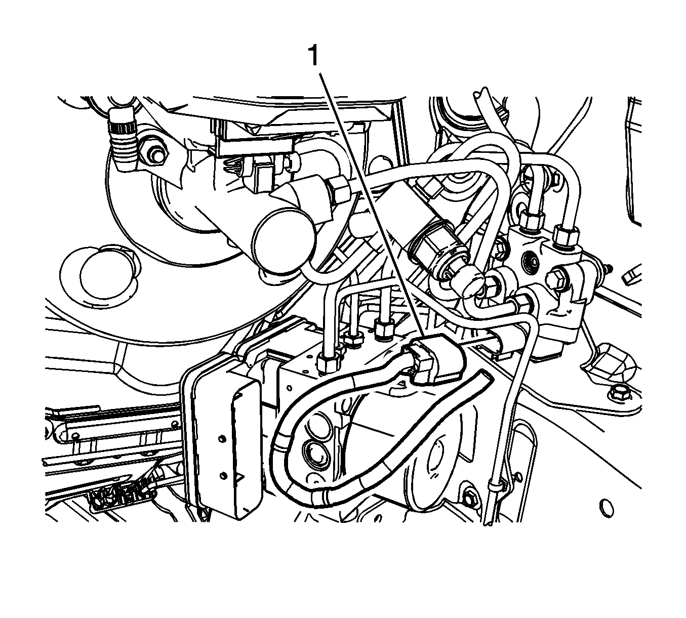
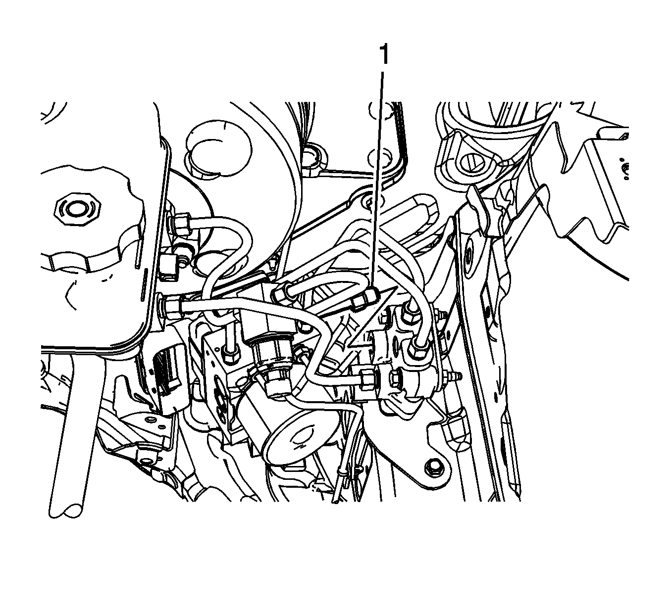
Rotate the brake pipe aside and cap the brake pipe fitting to prevent brake fluid loss and contamination.
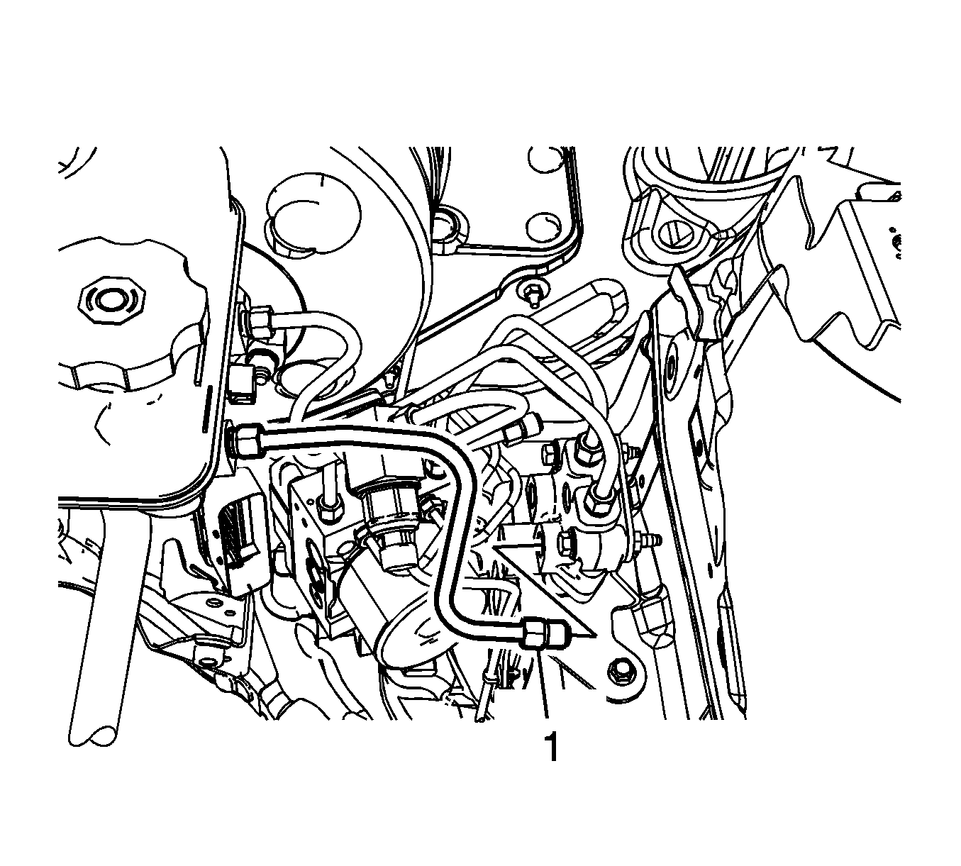
Rotate the brake pipe aside and cap the brake pipe fitting to prevent brake fluid loss and contamination.
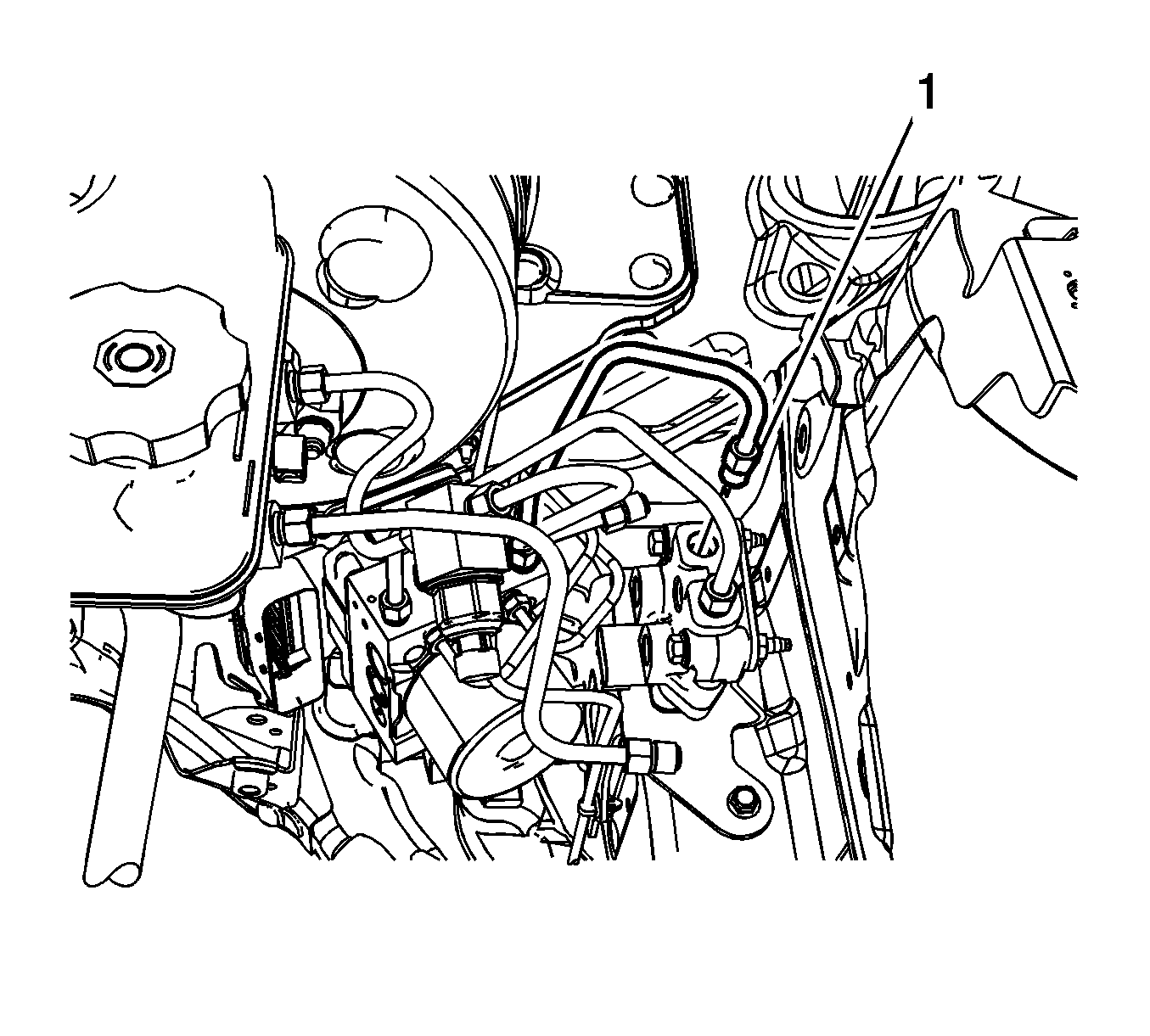
Rotate the brake pipe aside and cap the brake pipe fitting to prevent brake fluid loss and contamination.
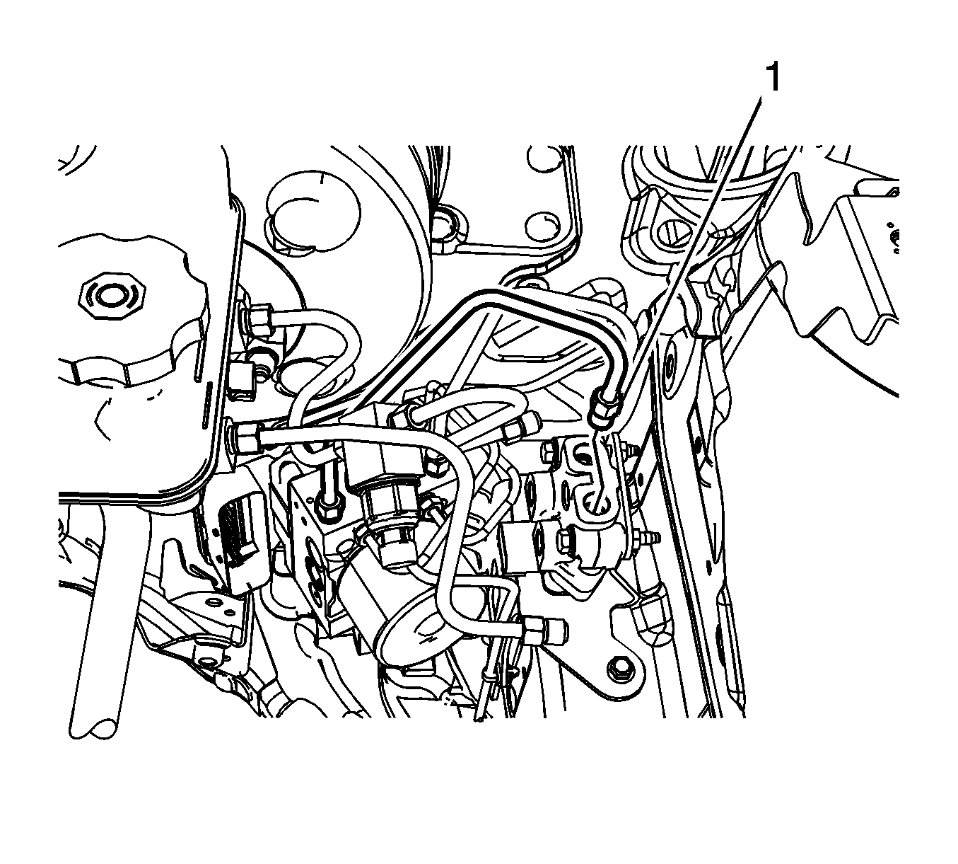
Rotate the brake pipe aside and cap the brake pipe fitting to prevent brake fluid loss and contamination.
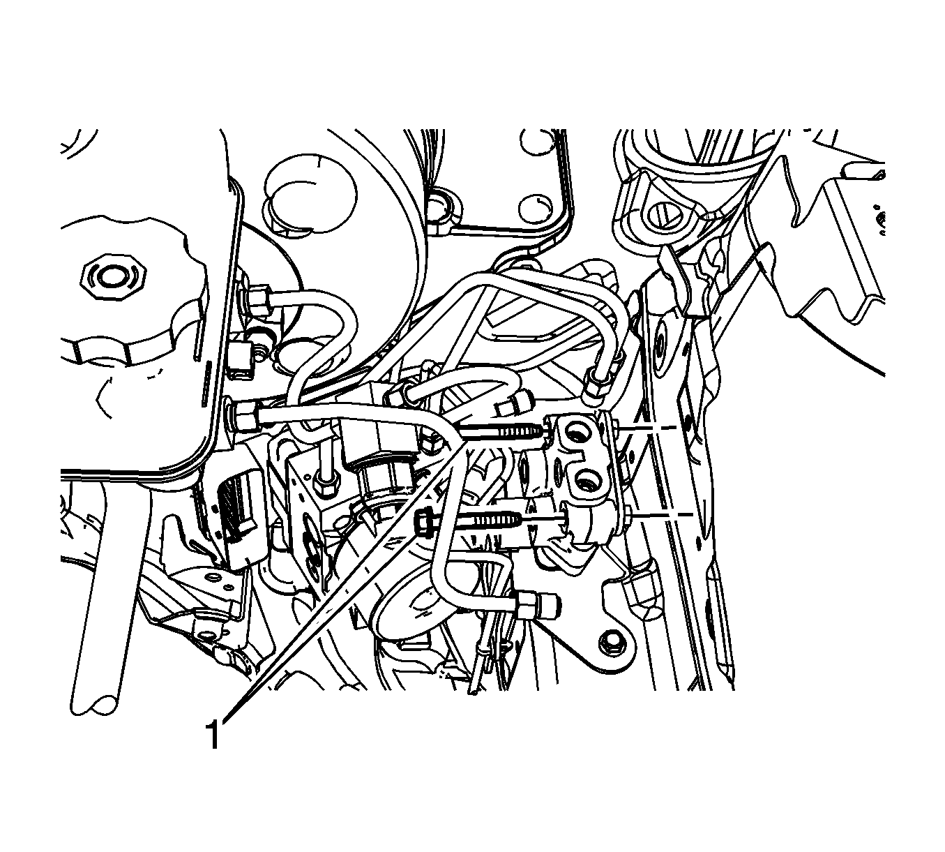
Installation Procedure
- Install the brake delay valve.
- Install the 2 brake delay valve bolts (1).
- Connect the secondary brake pipe outlet fitting (1) at the brake delay valve.
- Tighten the secondary brake pipe fitting at the BPMV.
- Connect the primary brake pipe outlet fitting (1) at the brake delay valve.
- Tighten the primary brake pipe fitting at the BPMV.
- Connect the secondary brake pipe inlet fitting (1) at the brake delay valve.
- Tighten the secondary brake pipe fitting at the master cylinder.
- Connect the primary brake pipe outlet fitting (1) at the brake delay valve.
- Tighten the primary brake pipe fitting at the master cylinder pressure sensor mounting block.
- Connect the brake delay valve electrical connector (1).
- Install the radiator surge tank. Refer to Radiator Surge Tank Replacement .
- Install the 12V battery. Refer to Battery Replacement .
- Bleed the hydraulic brake system. Refer to Hydraulic Brake System Bleeding .

Notice: Refer to Fastener Notice in the Preface section.
Tighten
Tighten the bolts to 10 N·m (89 lb in).

Tighten
Tighten the fitting to 18 N·m (13 lb ft).
Tighten
Tighten the fitting to 18 N·m (13 lb ft).

Tighten
Tighten the fitting to 18 N·m (13 lb ft).
Tighten
Tighten the fitting to 18 N·m (13 lb ft).

Tighten
Tighten the fitting to 18 N·m (13 lb ft).
Tighten
Tighten the fitting to 18 N·m (13 lb ft).

Tighten
Tighten the fitting to 18 N·m (13 lb ft).
Tighten
Tighten the fitting to 18 N·m (13 lb ft).

Warning: Refer to Brake Fluid Irritant Warning in the Preface section.
Caution: Refer to Brake Fluid Effects on Paint and Electrical Components Caution in the Preface section.
Removal Procedure
- Turn the ignition switch to the OFF position.
- Remove the 12V battery. Refer to Battery Replacement.
- Without draining the coolant or removing the hoses, remove and position aside the radiator surge tank. Refer to Radiator Surge Tank Replacement.
- Disconnect the brake delay valve electrical connector (1).
- Loosen, but do not remove, the primary brake pipe fitting at the master cylinder pressure sensor mounting block.
- Disconnect the primary brake pipe inlet fitting (1) at the brake delay valve.
- Loosen, but do not remove, the secondary brake pipe fitting at the master cylinder.
- Disconnect the secondary brake pipe inlet fitting (1) at the brake delay valve.
- Loosen, but do not remove, the primary brake pipe fitting at the brake pressure modulator valve (BPMV).
- Disconnect the primary brake pipe outlet fitting (1) at the brake delay valve.
- Loosen, but do not remove, the secondary brake pipe fitting at the BPMV.
- Disconnect the secondary brake pipe outlet fitting (1) at the brake delay valve.
- Remove the 2 brake delay valve bolts (1).
- Remove the brake delay valve.


Rotate the brake pipe aside and cap the brake pipe fitting to prevent brake fluid loss and contamination.

Rotate the brake pipe aside and cap the brake pipe fitting to prevent brake fluid loss and contamination.

Rotate the brake pipe aside and cap the brake pipe fitting to prevent brake fluid loss and contamination.

Rotate the brake pipe aside and cap the brake pipe fitting to prevent brake fluid loss and contamination.

Installation Procedure
- Install the brake delay valve.
- Install the 2 brake delay valve bolts (1).
- Connect the secondary brake pipe outlet fitting (1) at the brake delay valve.
- Tighten the secondary brake pipe fitting at the BPMV.
- Connect the primary brake pipe outlet fitting (1) at the brake delay valve.
- Tighten the primary brake pipe fitting at the BPMV.
- Connect the secondary brake pipe inlet fitting (1) at the brake delay valve.
- Tighten the secondary brake pipe fitting at the master cylinder.
- Connect the primary brake pipe outlet fitting (1) at the brake delay valve.
- Tighten the primary brake pipe fitting at the master cylinder pressure sensor mounting block.
- Connect the brake delay valve electrical connector (1).
- Install the radiator surge tank. Refer to Radiator Surge Tank Replacement.
- Install the 12V battery. Refer to Battery Replacement.
- Bleed the hydraulic brake system. Refer to Hydraulic Brake System Bleeding.

Caution: Refer to Fastener Caution in the Preface section.
Tighten
Tighten the bolts to 10 N·m (89 lb in).

Tighten
Tighten the fitting to 18 N·m (13 lb ft).
Tighten
Tighten the fitting to 18 N·m (13 lb ft).

Tighten
Tighten the fitting to 18 N·m (13 lb ft).
Tighten
Tighten the fitting to 18 N·m (13 lb ft).

Tighten
Tighten the fitting to 18 N·m (13 lb ft).
Tighten
Tighten the fitting to 18 N·m (13 lb ft).

Tighten
Tighten the fitting to 18 N·m (13 lb ft).
Tighten
Tighten the fitting to 18 N·m (13 lb ft).

