Removal Procedure
Caution: Refer to Brake Fluid Irritant Caution in the Preface section.
Notice: Refer to Brake Fluid Effects on Paint and Electrical Components Notice in the Preface section.
- Remove the underhood electrical center. Refer to Underhood Electrical Center or Junction Block Replacement .
- Remove and position aside the surge tank. Refer to Radiator Surge Tank Replacement .
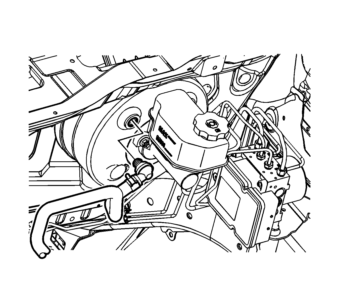
- Disconnect the vacuum brake booster vacuum check valve and hose from the vacuum brake booster and position aside.
- Remove the master cylinder. Refer to Master Cylinder Replacement .
- Remove the brake pressure modulator valve (BPMV). Refer to Brake Pressure Modulator Valve Replacement .
- Remove the driver knee bolster. Refer to Driver Knee Bolster Replacement .
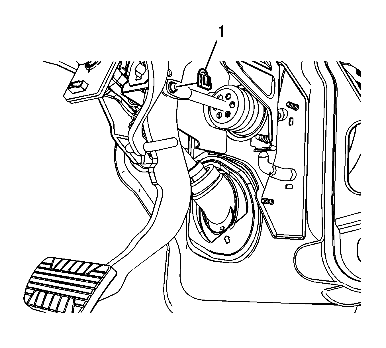
- Remove the vacuum brake booster pushrod retainer (1).
- Disconnect the vacuum brake booster pushrod from the brake pedal.
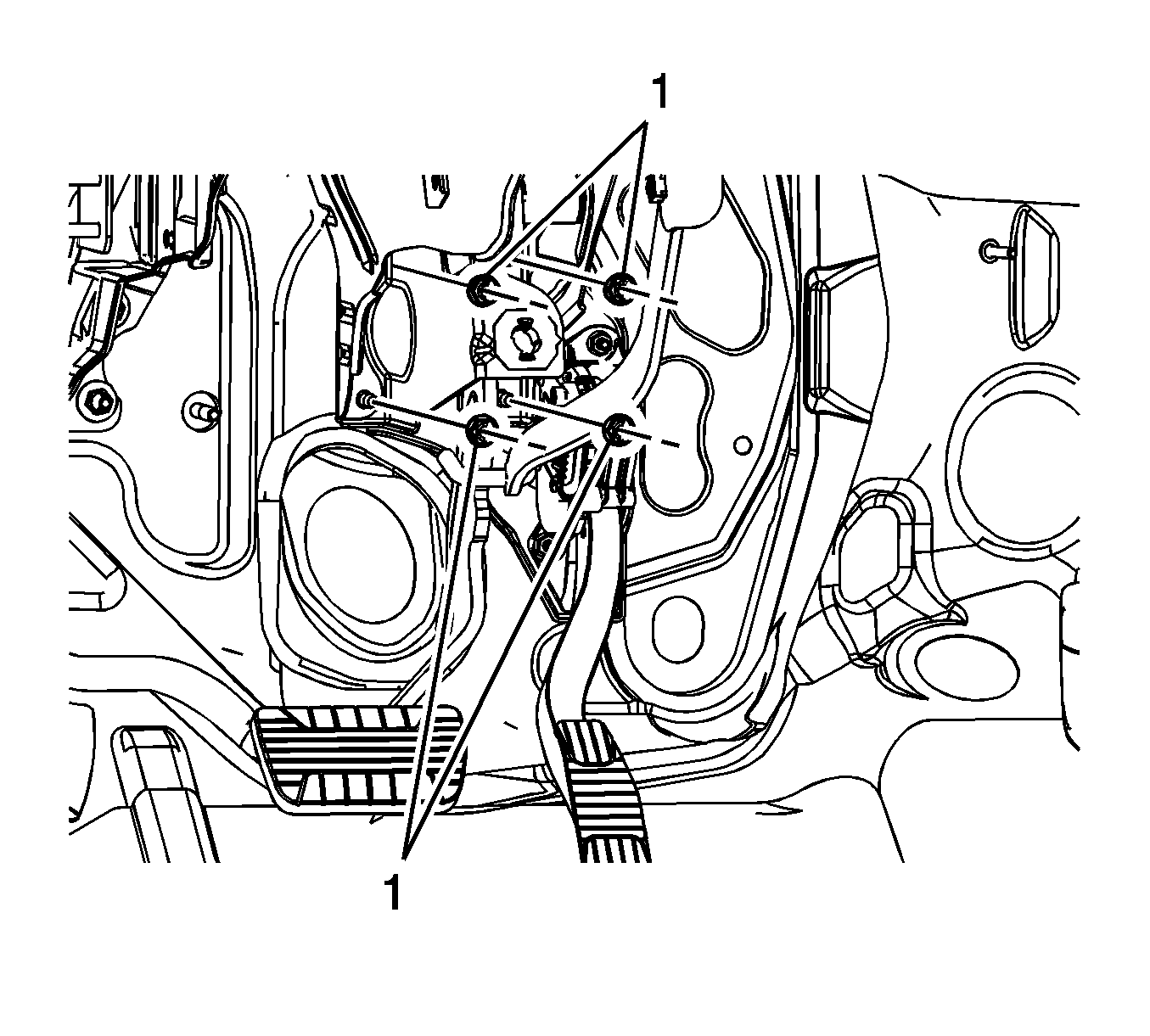
- Remove the 4 vacuum brake booster nuts (1).
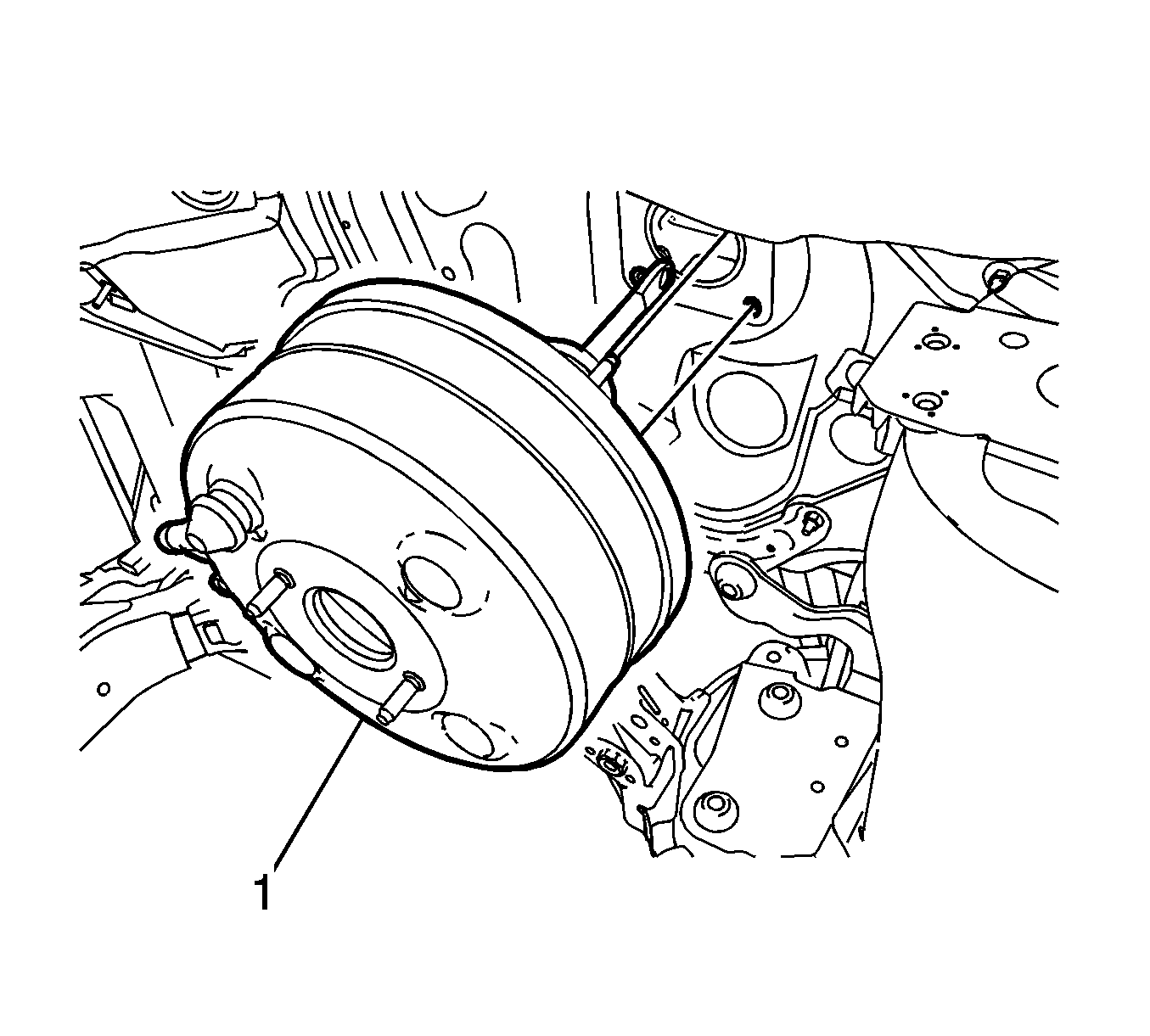
- Carefully pull the vacuum brake booster forward until the mounting studs clear the dash panel.
- Remove the vacuum brake booster (1).
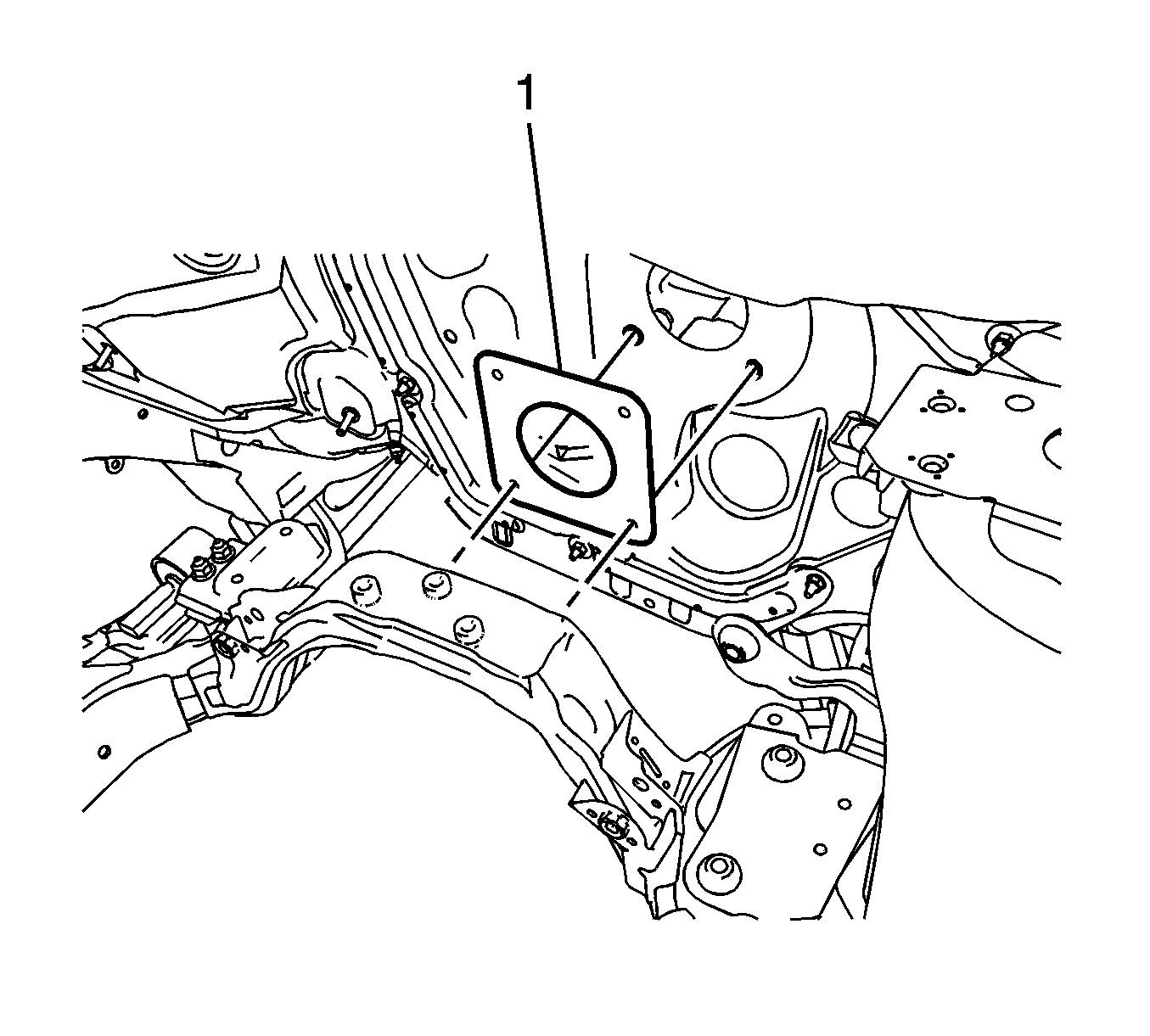
- Inspect the vacuum brake booster gasket (1) for damage and replace if necessary.
Important: Ensure the foam insulator on the mounting surface of the vacuum brake booster withdraws with the booster.
Installation Procedure
- Install the vacuum brake booster gasket (1).
- While guiding the brake booster pushrod and mounting studs through the dash panel, install the vacuum brake booster (1).
- Install the 4 vacuum brake booster nuts (1).
- Connect the vacuum brake booster pushrod to the brake pedal.
- Install the vacuum brake booster pushrod retainer (1).
- Install the driver knee bolster. Refer to Driver Knee Bolster Replacement .
- Install the BPMV. Refer to Brake Pressure Modulator Valve Replacement .
- Install the master cylinder. Refer to Master Cylinder Replacement .
- Connect the vacuum brake booster vacuum check valve and hose to the vacuum brake booster.
- Install the surge tank. Refer to Radiator Surge Tank Replacement .
- Install the underhood electrical center. Refer to Underhood Electrical Center or Junction Block Replacement .

Important: Ensure the foam insulator on the mounting surface of the vacuum brake booster is properly installed on the booster.

Notice: Refer to Fastener Notice in the Preface section.

Tighten
Tighten the nuts to 25 N·m (18 lb ft).

Rotate the vacuum brake booster pushrod retainer 360 degrees to ensure it is properly installed.

Removal Procedure
Warning: Refer to Brake Fluid Irritant Warning in the Preface section.
Caution: Refer to Brake Fluid Effects on Paint and Electrical Components Caution in the Preface section.
- Remove the underhood electrical center. Refer to Underhood Electrical Center or Junction Block Replacement.
- Remove and position aside the surge tank. Refer to Radiator Surge Tank Replacement.
- Disconnect the vacuum brake booster vacuum check valve and hose from the vacuum brake booster and position aside.
- Remove the master cylinder. Refer to Master Cylinder Replacement.
- Remove the brake pressure modulator valve (BPMV). Refer to Brake Pressure Modulator Valve Replacement.
- Remove the driver knee bolster. Refer to Driver Knee Bolster Replacement.
- Remove the vacuum brake booster pushrod retainer (1).
- Disconnect the vacuum brake booster pushrod from the brake pedal.
- Remove the 4 vacuum brake booster nuts (1).
- Carefully pull the vacuum brake booster forward until the mounting studs clear the dash panel.
- Remove the vacuum brake booster (1).
- Inspect the vacuum brake booster gasket (1) for damage and replace if necessary.


Note: Ensure the foam insulator on the mounting surface of the vacuum brake booster withdraws with the booster.

Installation Procedure
- Install the vacuum brake booster gasket (1).
- While guiding the brake booster pushrod and mounting studs through the dash panel, install the vacuum brake booster (1).
- Install the 4 vacuum brake booster nuts (1).
- Connect the vacuum brake booster pushrod to the brake pedal.
- Install the vacuum brake booster pushrod retainer (1).
- Install the driver knee bolster. Refer to Driver Knee Bolster Replacement.
- Install the BPMV. Refer to Brake Pressure Modulator Valve Replacement.
- Install the master cylinder. Refer to Master Cylinder Replacement.
- Connect the vacuum brake booster vacuum check valve and hose to the vacuum brake booster.
- Install the surge tank. Refer to Radiator Surge Tank Replacement.
- Install the underhood electrical center. Refer to Underhood Electrical Center or Junction Block Replacement.


Note: Ensure the foam insulator on the mounting surface of the vacuum brake booster is properly installed on the booster.
Caution: Refer to Fastener Caution in the Preface section.

Tighten
Tighten the nuts to 25 N·m (18 lb ft).

Rotate the vacuum brake booster pushrod retainer 360 degrees to ensure it is properly installed.

