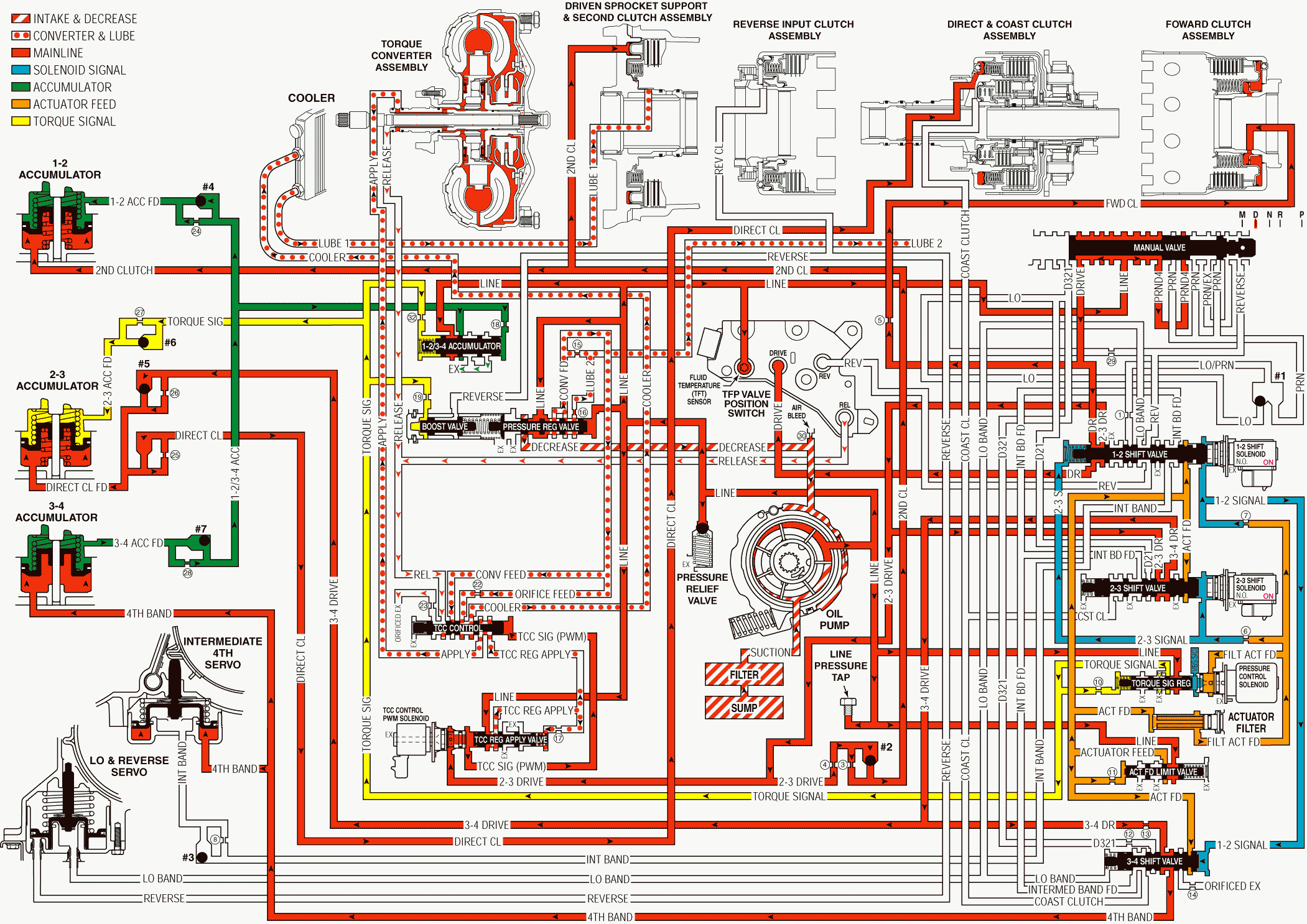
Overdrive Range, Fourth Gear - Torque Converter Clutch Applied With Electronic Range Select Mode
When operating conditions are appropriate, the PCM energizes the 1-2 shift solenoid valve in order to shift the transmission into Fourth gear. In addition, the TCC is applied in Fourth gear. The manual valve remains in the Overdrive position and line pressure continues to feed the Drive and the PRND4 fluid circuits.
Intermediate and Fourth Band Applied
1-2 Shift Solenoid Valve
The PCM energizes the normally open 1-2 shift solenoid valve, which blocks the 1-2 signal fluid from exhausting. The 1-2 signal fluid pressure is routed to both the 1-2 and the 3-4 shift valves.
1-2 Shift Valve
The 1-2 signal fluid pressure does not affect the 1-2 shift valve. A combination of spring force and the 2-3 signal fluid pressure keeps the 1-2 shift valve in the upshifted position.
3-4 Shift Valve
The 1-2 signal fluid pressure moves the valve against a spring force and into the Fourth gear position. The 3-4 drive fluid is routed into the fourth band fluid circuit.
Intermediate and Fourth Servo
The 1-2 signal fluid pressure moves the valve against a spring force and into the Fourth gear position. The 3-4 drive fluid is routed into the fourth band fluid circuit.
Shift Accumulation
3-4 Accumulator
The fourth band fluid is also routed to the 3-4 accumulator piston. Fourth band fluid pressure moves the piston against a combination of spring force and 3-4 accumulator feed fluid pressure. This action absorbs initial fourth band fluid pressure in order to cushion the intermediate and Fourth band apply. The movement of the 3-4 accumulator piston forces some fluid out of the accumulator.
3-4 Accumulator Valve
The 3-4 accumulator feed fluid which is forced from the 3-4 accumulator unseats the #7 checkball and the fluid is routed back to the 3-4 accumulator valve. This pressure forces the 1-2/3-4 accumulator valve against a combination of spring force and torque signal fluid pressure in order to regulate the exhaust of excess accumulator fluid. This regulation provides additional control for the intermediate and fourth band apply.
Torque Converter Clutch Applied
TCC Control Solenoid Valve
When conditions are appropriate, the PCM energized the TCC control solenoid valve in order to initiate the TCC apply. The solenoid valve is pulse width modulated (PWM) in order to provide a smooth TCC apply (Refer to the electrical controls section for a detailed description of the TCC control solenoid valve operation). When energized, the solenoid valve modulates the filtered 2-3 drive fluid into the TCC signal fluid circuit.
TCC Regulated Apply Valve
TCC Signal fluid pressure modulates the valve against a combination of spring force and TCC regulated apply fluid pressure. This action directs line pressure into the TCC regulated apply fluid circuit in relation to vehicle operating conditions.
TCC Control Valve
Modulated TCC signal fluid pressure moves the valve against a spring force in relation to vehicle operating conditions. This action regulates TCC regulated apply fluid into the apply fluid circuit. At the same time, the release fluid circuit is opened to an orificed exhaust. In this position the valve directs TCC feed limit fluid in order to feed the cooler fluid circuit.
Torque Converter Clutch (TCC)
Apply fluid is routed to the torque converter at the same time that release fluid exhausts from the converter. Apply fluid pressure applies the TCC.
A/T Fluid Pressure Manual Valve Position Switch (TFP Val. Position Sw.) Assembly
Release fluid also exhausts from the TFP Val. Position Sw. Assembly, which signals to the PCM that the TCC is released.
Overdrive Range, Fourth Gear - TCC Applied - With Electronic Range Select Mode

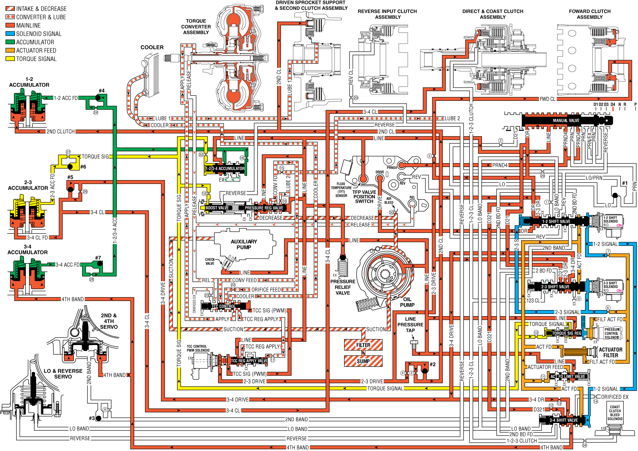
Overdrive Range, Fourth Gear - Torque Converter Clutch Applied L4 Hybrid
When operating conditions are appropriate, the PCM energizes the 1-2 shift solenoid valve in order to shift the transmission into Fourth gear. In addition, the TCC is applied in Fourth gear. The manual valve remains in the Overdrive position and line pressure continues to feed the Drive and the PRND4 fluid circuits.
Under certain conditions the hybrid vehicles engine will shut off and the electric auxiliary transmission fluid pump will start running to keep the transmission pressurized and ready for the engine restart. This engine off condition is a fuel economy feature and the L4 hybrid transmission's electric auxiliary fluid pump is an enabling component.
Intermediate and Fourth Band Applied
1-2 Shift Solenoid Valve
The PCM energizes the normally open 1-2 shift solenoid valve, which blocks the 1-2 signal fluid from exhausting. The 1-2 signal fluid pressure is routed to both the 1-2 and the 3-4 shift valves.
1-2 Shift Valve
The 1-2 signal fluid pressure does not affect the 1-2 shift valve. A combination of spring force and the 2-3 signal fluid pressure keeps the 1-2 shift valve in the upshifted position.
3-4 Shift Valve
The 1-2 signal fluid pressure moves the valve against a spring force and into the Fourth gear position. The 3-4 drive fluid is routed into the fourth band fluid circuit.
Intermediate and Fourth Servo
The 1-2 signal fluid pressure moves the valve against a spring force and into the Fourth gear position. The 3-4 drive fluid is routed into the fourth band fluid circuit.
Shift Accumulation
3-4 Accumulator
The fourth band fluid is also routed to the 3-4 accumulator piston. Fourth band fluid pressure moves the piston against a combination of spring force and 3-4 accumulator feed fluid pressure. This action absorbs initial fourth band fluid pressure in order to cushion the intermediate and Fourth band apply. The movement of the 3-4 accumulator piston forces some fluid out of the accumulator.
3-4 Accumulator Valve
The 3-4 accumulator feed fluid which is forced from the 3-4 accumulator unseats the #7 checkball and the fluid is routed back to the 3-4 accumulator valve. This pressure forces the 1-2/3-4 accumulator valve against a combination of spring force and torque signal fluid pressure in order to regulate the exhaust of excess accumulator fluid. This regulation provides additional control for the intermediate and fourth band apply.
Torque Converter Clutch Applied
TCC Control Solenoid Valve
When conditions are appropriate, the PCM energized the TCC control solenoid valve in order to initiate the TCC apply. The solenoid valve is pulse width modulated (PWM) in order to provide a smooth TCC apply (Refer to the electrical controls section for a detailed description of the TCC control solenoid valve operation). When energized, the solenoid valve modulates the filtered 2-3 drive fluid into the TCC signal fluid circuit.
TCC Regulated Apply Valve
TCC Signal fluid pressure modulates the valve against a combination of spring force and TCC regulated apply fluid pressure. This action directs line pressure into the TCC regulated apply fluid circuit in relation to vehicle operating conditions.
TCC Control Valve
Modulated TCC signal fluid pressure moves the valve against a spring force in relation to vehicle operating conditions. This action regulates TCC regulated apply fluid into the apply fluid circuit. At the same time, the release fluid circuit is opened to an orificed exhaust. In this position the valve directs TCC feed limit fluid in order to feed the cooler fluid circuit.
Torque Converter Clutch (TCC)
Apply fluid is routed to the torque converter at the same time that release fluid exhausts from the converter. Apply fluid pressure applies the TCC.
A/T Fluid Pressure Manual Valve Position Switch (TFP Val. Position Sw.) Assembly
Release fluid also exhausts from the TFP Val. Position Sw. Assembly, which signals to the PCM that the TCC is released.
Overdrive Range, Fourth Gear - TCC Applied - L4 Hybrid

