Frame Replacement 4T45-E Transmission
Special Tools
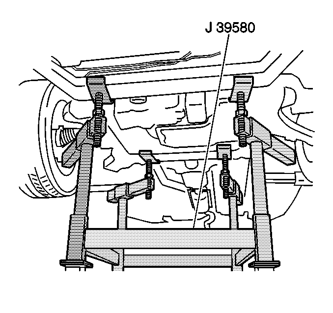
J 39580 Engine Support Table
Removal Procedure
- Remove the front compartment sight shield. Refer to Front Compartment Sight Shields Replacement.
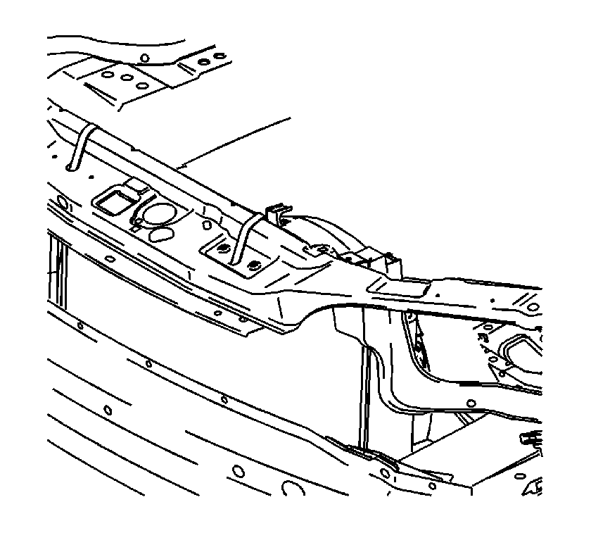
- Secure the radiator, air conditioning condenser, and fan module assembly to the upper tie bar to keep the assembly with the vehicle when the frame is removed.
- Install the engine support fixture. Refer to Engine Support Fixture.
- Raise and support the vehicle. Refer to Lifting and Jacking the Vehicle.
- Remove the tire and wheel assemblies. Refer to Tire and Wheel Removal and Installation.
- Remove the engine splash shields. Refer to Engine Splash Shield Replacement.
- Remove the two push pins securing the front bumper air deflector to the frame. Refer to Front Bumper Fascia Air Deflector Replacement.
- Remove both left and right stabilizer shaft insulator clamps. Refer to Stabilizer Shaft Insulator Replacement.
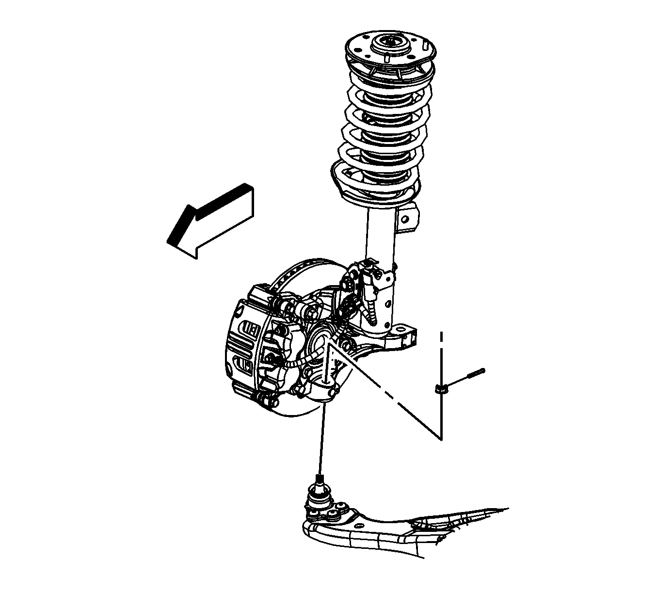
- Remove the lower ball joints from the steering knuckles. Refer to Lower Control Arm Replacement.
- Disconnect the steering shaft coupling from the steering gear. Refer to Steering Shaft Coupling Replacement.
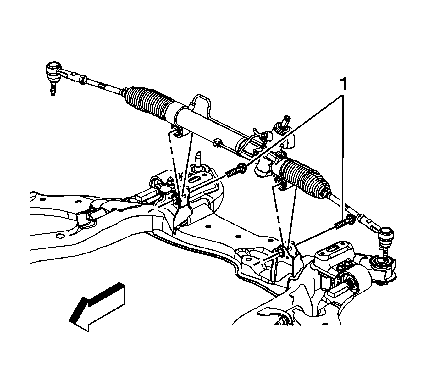
- Remove the power steering gear mounting bolts (1) and secure the gear out of the way using mechanic's wire or equivalent. Refer to Steering Gear Replacement.
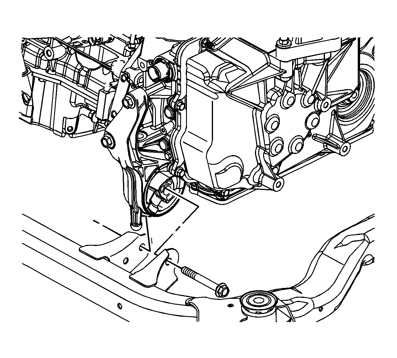
- Remove the front transmission mount thru bolt.
- Remove the rear transmission mount bolts from the frame.
- Lower the vehicle until the frame contacts the J 39580 .
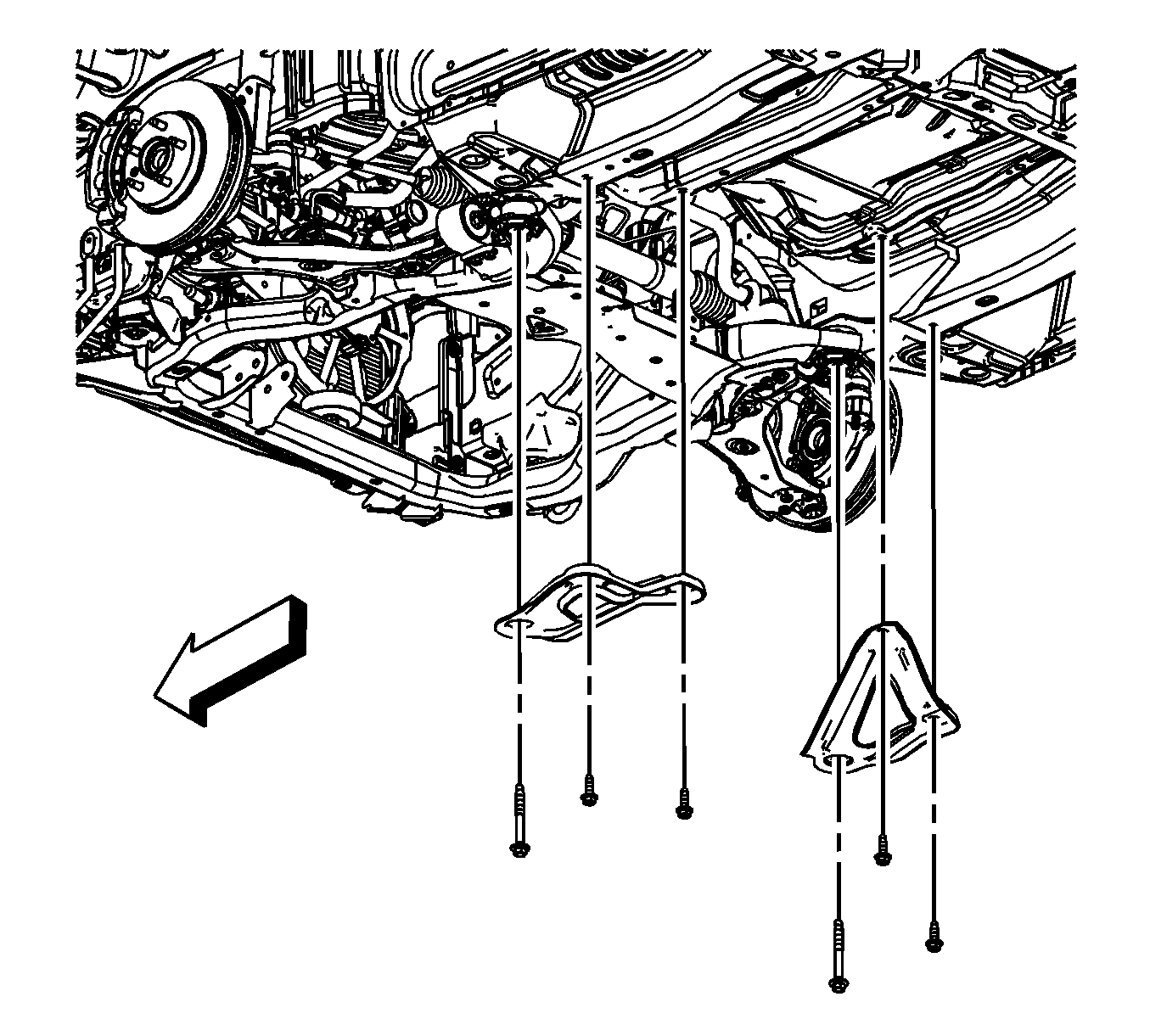
- Remove the frame reinforcements. Refer to Drivetrain and Front Suspension Frame Reinforcement Replacement.
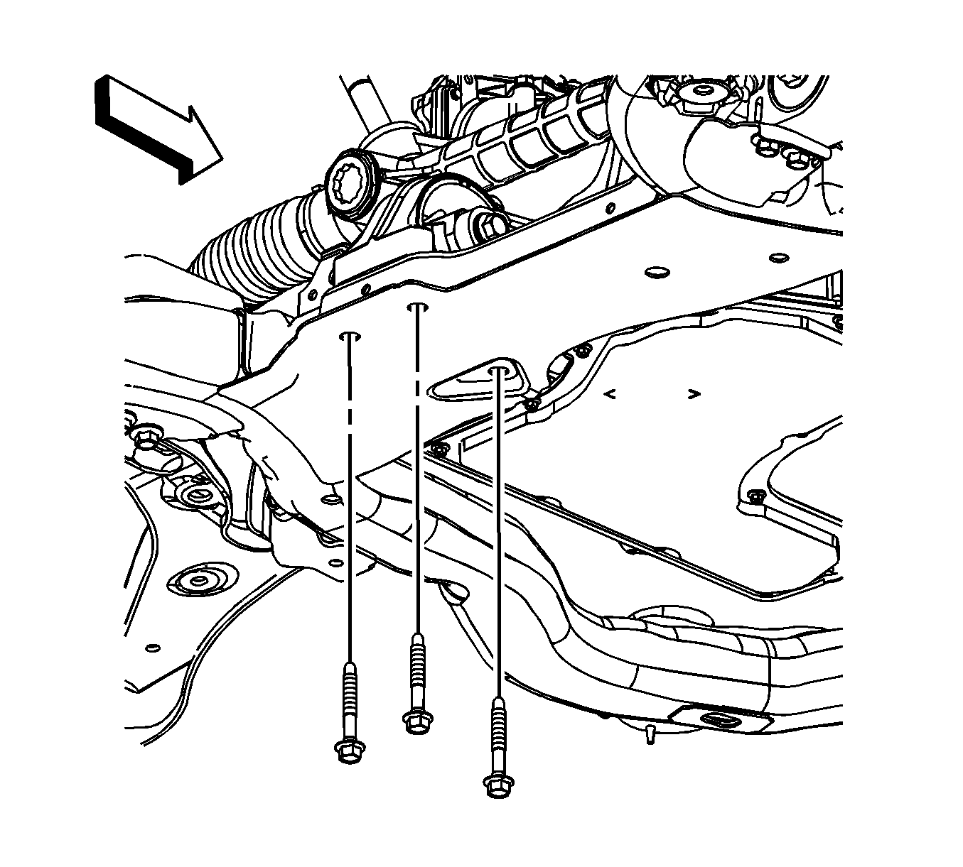
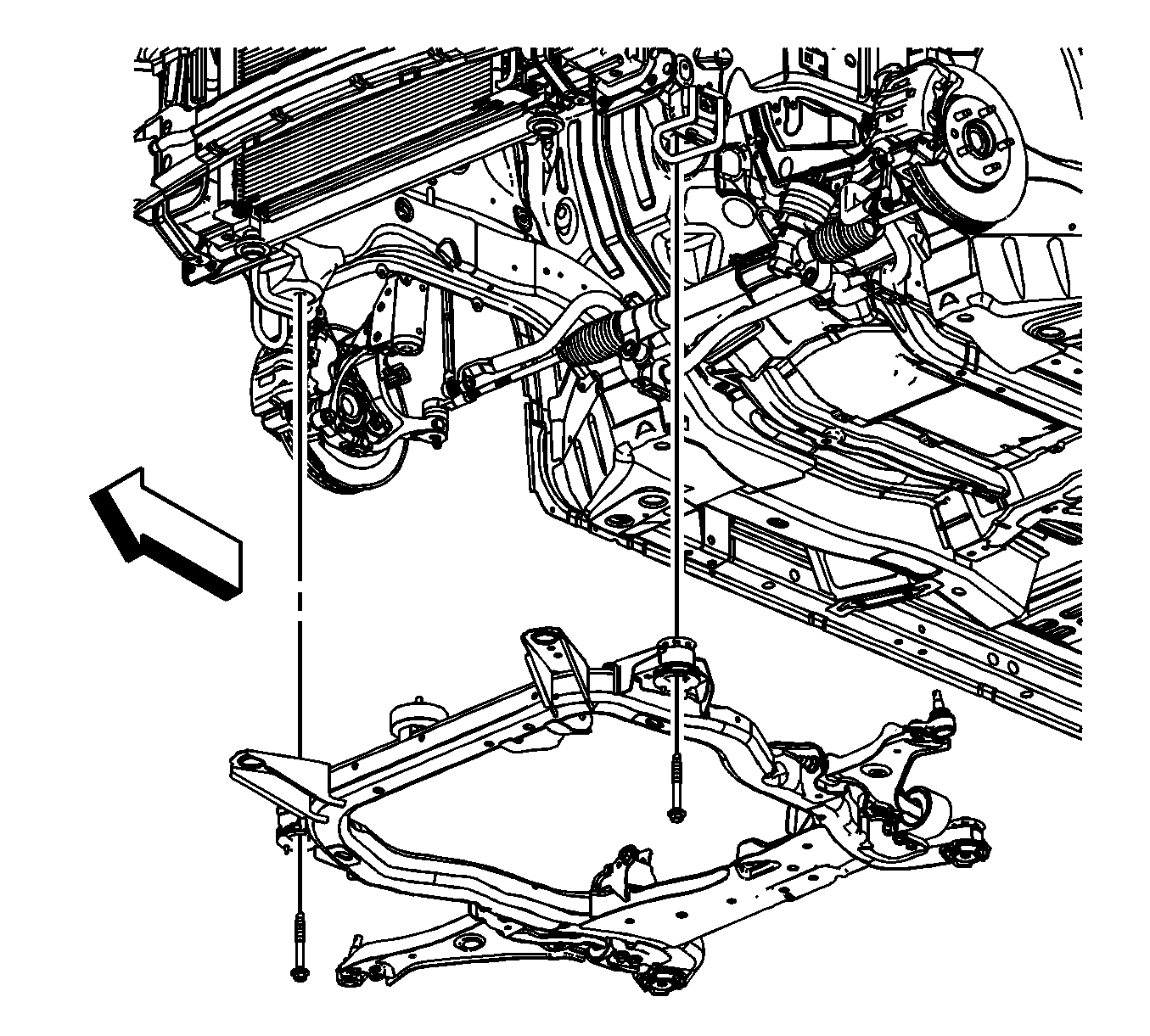
- Remove the front frame bolts.
- Raise the vehicle off of the frame.
- If replacing the frame, remove the lower control arms. Refer to Lower Control Arm Replacement.
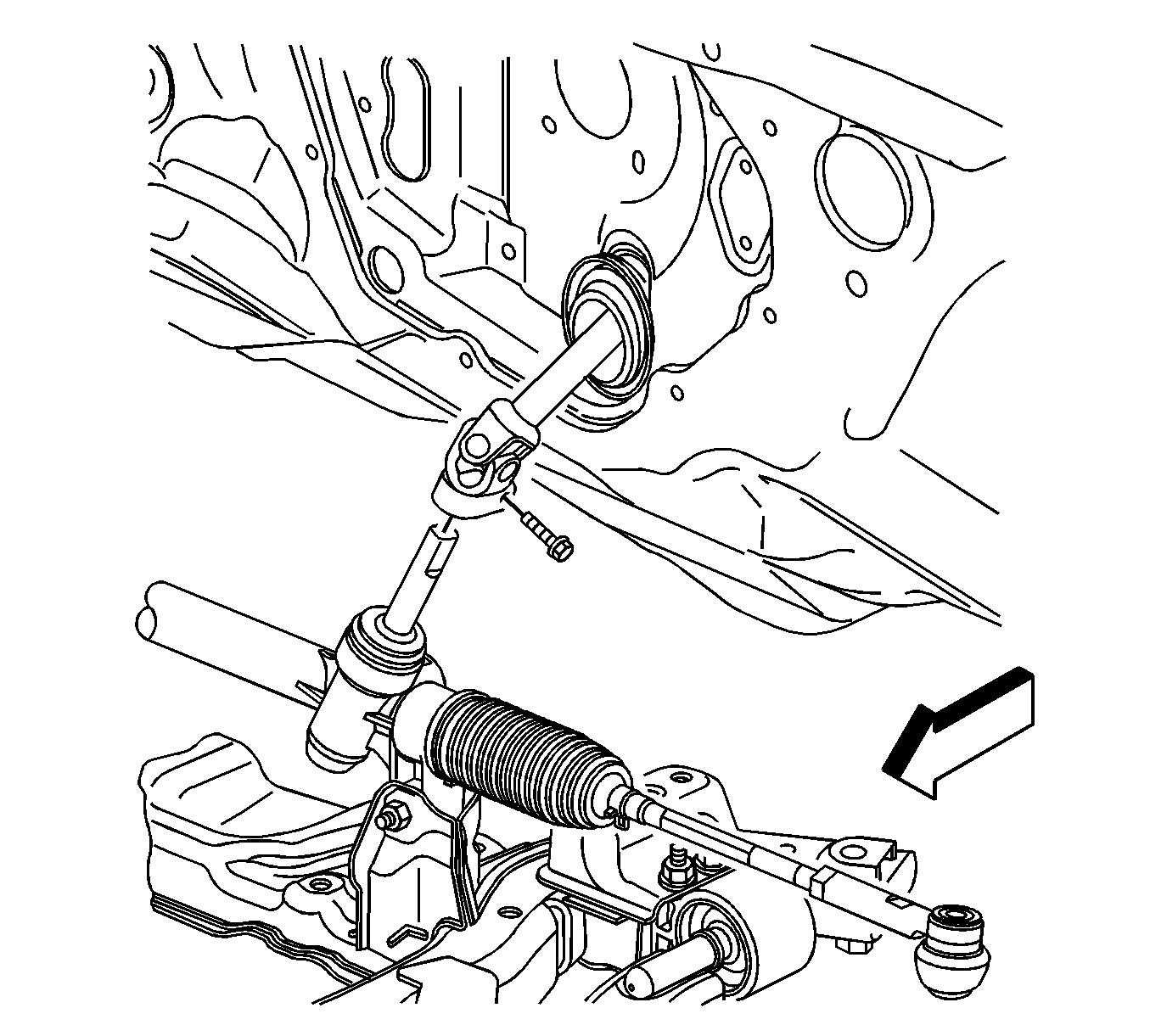
Important: Whenever the steering gear is moved in relation to the body, disconnect the intermediate shaft from the steering gear.
Installation Procedure
- If removed, Install the lower control arms. Refer to Lower Control Arm Replacement.
- Lower the vehicle on to the frame.
- Install the front frame bolts.
- Install the frame reinforcement. Refer to Drivetrain and Front Suspension Frame Reinforcement Replacement.
- Raise the vehicle off of the J 39580 .
- Install the rear transmission mount bolts to the frame.
- Install the front transmission mount thru bolt.
- Install the power steering gear mounting bolts (1). Refer to Steering Gear Replacement.
- Install the steering shaft coupling to the steering gear. Refer to Steering Shaft Coupling Replacement.
- Install the lower ball joints to the steering knuckles. Refer to Lower Control Arm Replacement.
- Install both left and right stabilizer shaft insulator clamps. Refer to Stabilizer Shaft Insulator Replacement.
- Install the two push pins securing the front bumper air deflector to the frame. Refer to Front Bumper Fascia Air Deflector Replacement.
- Install the engine splash shields. Refer to Engine Splash Shield Replacement.
- Install the tire and wheel assemblies. Refer to Tire and Wheel Removal and Installation.
- Remove the engine support fixture. Refer to Engine Support Fixture.
- Release the radiator, air conditioning condenser, and fan module assembly from the upper tie bar.
- Install the front compartment sight shield. Refer to Front Compartment Sight Shields Replacement.
- Check the wheel alignment. Refer to Wheel Alignment Measurement.

Notice: Refer to Fastener Notice in the Preface section.

Tighten
Tighten the bolts to 155 N·m (114 lb ft).


Tighten
Tighten the bolts to 50 N·m (37 lb ft).

Tighten
Tighten the bolt to 110 N·m (81 lb ft).


Frame Replacement 6T70 Transmission
Special Tools
J 39580 Engine Support Table
Removal Procedure
- Remove the front compartment sight shield. Refer to Front Compartment Sight Shields Replacement.
- Secure the radiator, air conditioning condenser, and fan module assembly to the upper tie bar to keep the assembly with the vehicle when the frame is removed.
- Install the engine support fixture. Refer to Engine Support Fixture for the 3.5 L LZ4 engine or Engine Support Fixture for the 3.6 L LY7 engine.
- Raise and support the vehicle. Refer to Lifting and Jacking the Vehicle.
- Remove the tire and wheel assemblies. Refer to Tire and Wheel Removal and Installation.
- Remove the engine splash shields. Refer to Engine Splash Shield Replacement.
- Remove the two push pins securing the front bumper air deflector to the frame. Refer to Front Bumper Fascia Air Deflector Replacement.
- Remove the catalytic converters. Refer to Catalytic Converter Replacement - Left Side and Catalytic Converter Replacement - Right Side.
- Remove the propeller shaft if the vehicle is equipped with AWD. Refer to Propeller Shaft Replacement.
- Remove both left and right stabilizer shaft insulator clamps. Refer to Stabilizer Shaft Insulator Replacement.
- Remove the lower ball joints from the steering knuckles. Refer to Lower Control Arm Replacement.
- Disconnect the steering shaft coupling from the steering gear. Refer to Steering Shaft Coupling Replacement.
- Remove the power steering gear mounting bolts (1) and secure the gear out of the way using mechanics wire or equivalent. Refer to Steering Gear Replacement.
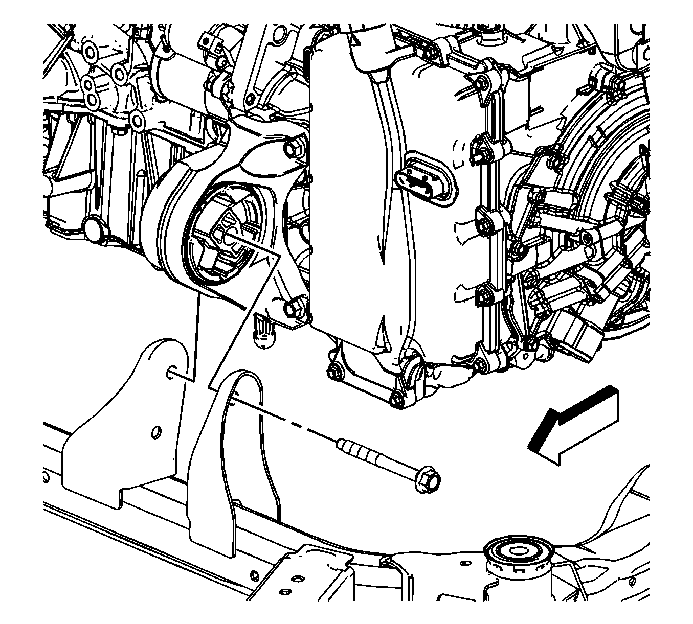
- Remove the front transmission mount thru bolt.
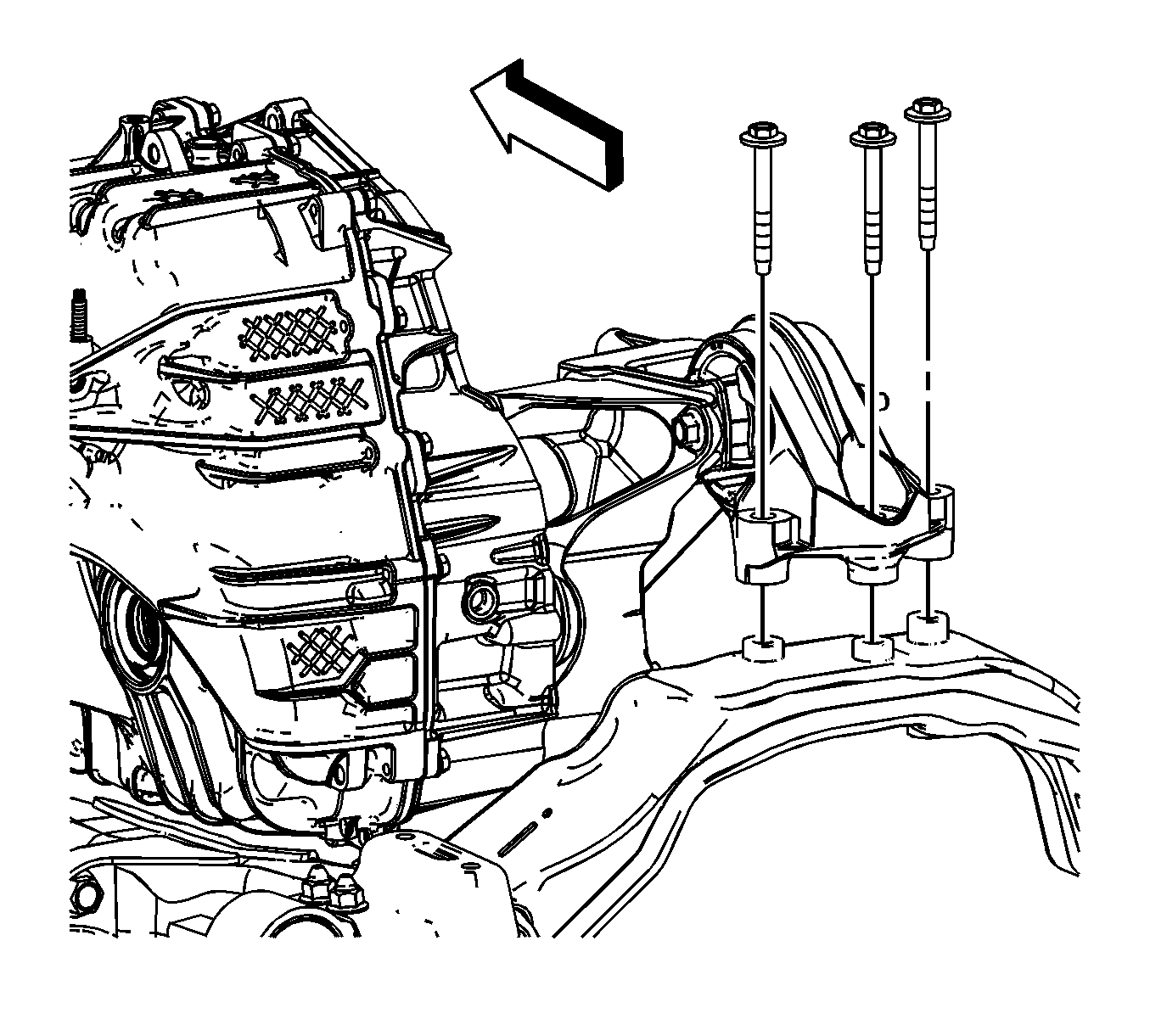
- Remove the rear transmission mount bolts from the frame.
- Lower the vehicle until the frame contacts the J 39580 .
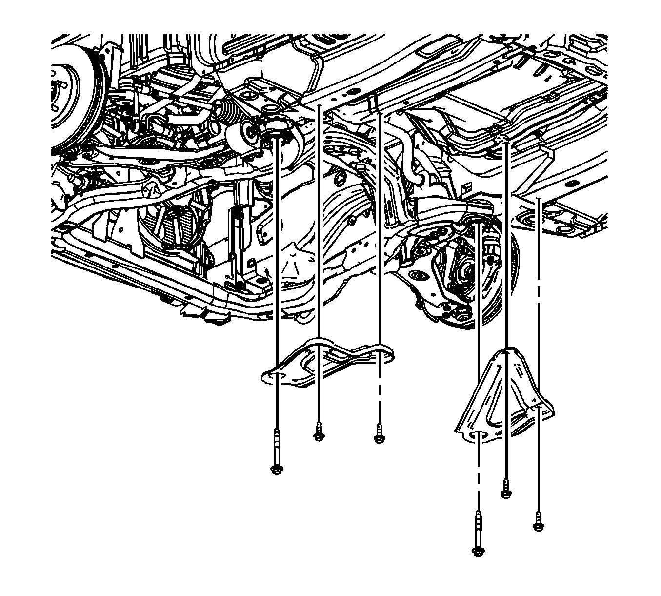
- Remove the frame reinforcements. Refer to Drivetrain and Front Suspension Frame Reinforcement Replacement.
- Remove the front frame bolts.
- Raise the vehicle off of the frame.
- If replacing the frame, remove the lower control arms. Refer to Lower Control Arm Replacement.


Important: Whenever the steering gear is moved in relation to the body, disconnect the intermediate shaft from the steering gear.


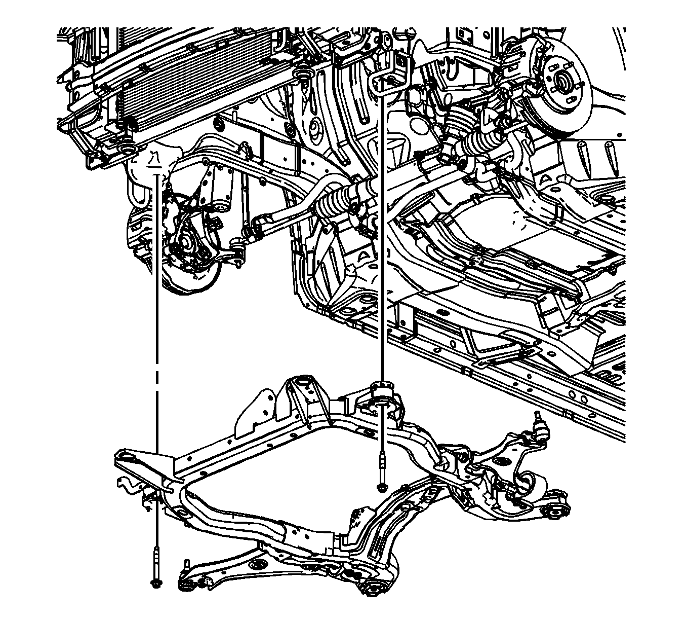
Installation Procedure
- If removed, install the lower control arms. Refer to Lower Control Arm Replacement.
- Lower the vehicle on to the frame.
- Install the front frame bolts.
- Install the frame reinforcement. Refer to Drivetrain and Front Suspension Frame Reinforcement Replacement.
- Raise the vehicle off of the J 39580 .
- Install the rear transmission mount bolts to the frame.
- Install the front transmission mount thru bolt.
- Install the power steering gear mounting bolts (1). Refer to Steering Gear Replacement.
- Install the steering shaft coupling to the steering gear. Refer to Steering Shaft Coupling Replacement.
- Install the lower ball joints to the steering knuckles. Refer to Lower Control Arm Replacement.
- Install the propeller shaft if the vehicle is equipped with AWD. Refer to Propeller Shaft Replacement.
- Install the catalytic converters. Refer to Catalytic Converter Replacement - Left Side and Catalytic Converter Replacement - Right Side.
- Install both left and right stabilizer shaft insulator clamps. Refer to Stabilizer Shaft Insulator Replacement.
- Install the two push pins securing the front bumper air deflector to the frame. Refer to Front Bumper Fascia Air Deflector Replacement.
- Install the engine splash shields. Refer to Engine Splash Shield Replacement.
- Install the tire and wheel assemblies. Refer to Tire and Wheel Removal and Installation.
- Remove the engine support fixture. Refer to Engine Support Fixture for the 3.5 L LZ4 engine or Engine Support Fixture for the 3.6 L LY7 engine.
- Release the radiator, air conditioning condenser, and fan module assembly from the upper tie bar.
- Install the front compartment sight shield. Refer to Front Compartment Sight Shields Replacement.
- Check the wheel alignment. Refer to Wheel Alignment Measurement.

Notice: Refer to Fastener Notice in the Preface section.

Tighten
Tighten the bolts to 155 N·m (114 lb ft).


Tighten
Tighten the bolts to 50 N·m (37 lb ft).

Tighten
Tighten the bolt to 110 N·m (81 lb ft).


Frame Replacement 2MT70 Transmission
Special Tools
J 39580 Engine Support Table
Removal Procedure
- Disable the hybrid high voltage system. Refer to High Voltage Disabling
- Disconnect the 12 volt battery negative cable. Refer to Battery Negative Cable Disconnection and Connection
- Remove the front compartment sight shield. Refer to Front Compartment Sight Shields Replacement.
- Secure the radiator, air conditioning condenser, and fan module assembly to the upper tie bar to keep the assembly with the vehicle when the frame is removed.
- Install the engine support fixture. Refer to Engine Support Fixture.
- Raise and support the vehicle. Refer to Lifting and Jacking the Vehicle.
- Remove the front tire and wheel assemblies. Refer to Tire and Wheel Removal and Installation.
- Remove the engine splash shields. Refer to Engine Splash Shield Replacement.
- Remove the air deflector from the frame. Refer to Front Bumper Fascia Air Deflector Replacement.
- Remove the front catalytic converters. Refer to Catalytic Converter Replacement - Left Side.
- Disconnect the lower ball joints from the steering knuckles. Refer to Lower Control Arm Replacement.
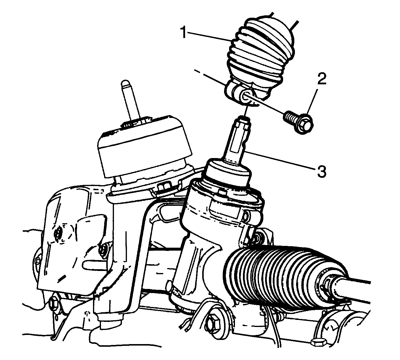
- Disconnect the steering shaft coupling (1) from the steering gear. Refer to Steering Shaft Coupling Replacement.
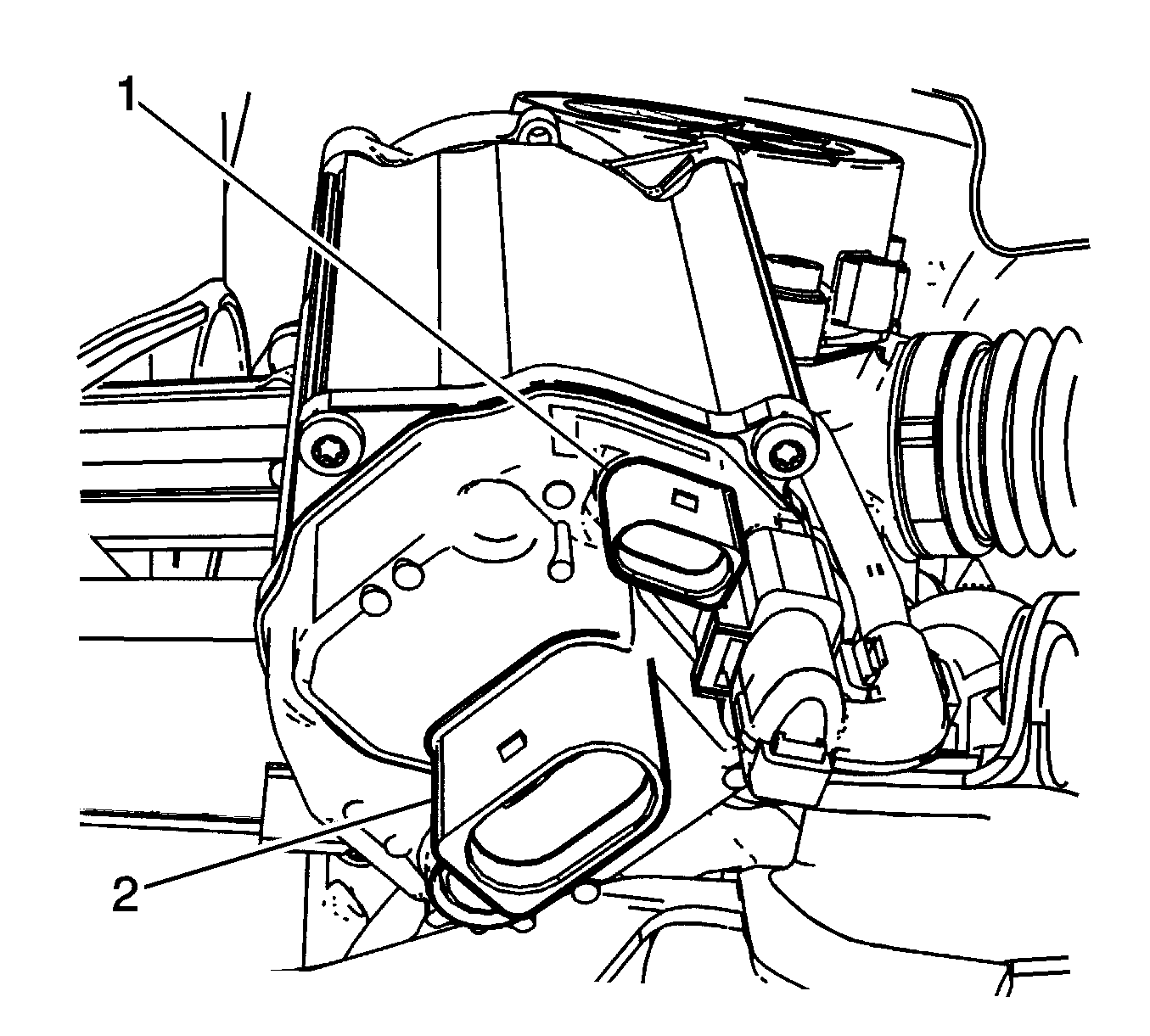
- Disconnect the electrical connectors (1, 2) from the Electronic Power Steering rack motor.
- Disconnect the out tie rod ends from the steering knuckle. Refer to Steering Linkage Outer Tie Rod Replacement
- Disconnect the stabilizer links from the stabilizer bar. Refer to Stabilizer Shaft Link Replacement
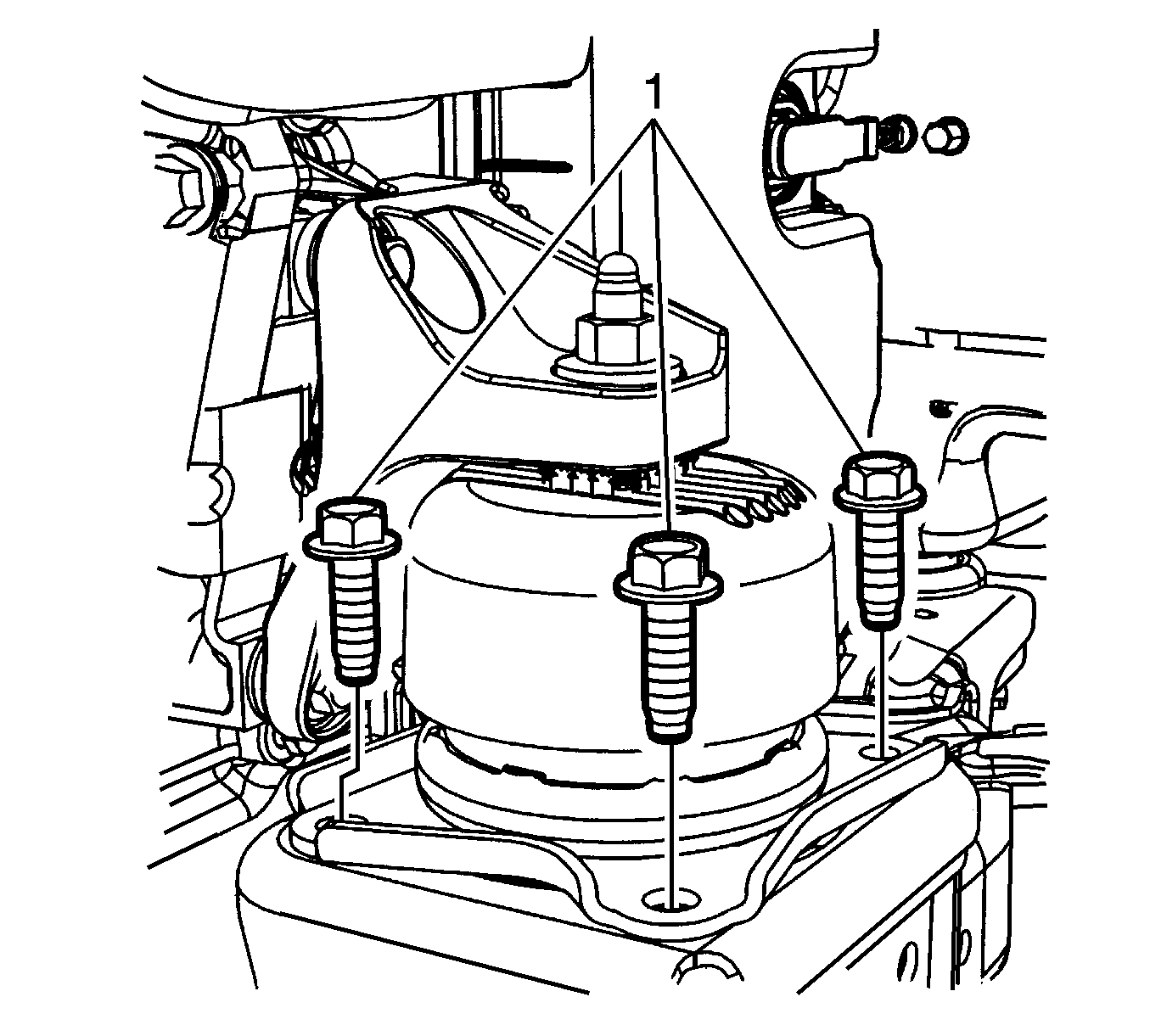
- Remove the three front transmission mount retaining bolts (1) from the frame.
- Remove the rear transmission mount to bracket retaining nut (1).
- Remove the steering gear electric motor ground strap from the underbody.
- Remove the four bolts that attach the electric brake control module (EBCM) (1) to the frame.
- Lower the vehicle until the frame contacts the J 39580 .
- Remove the frame reinforcements. Refer to Drivetrain and Front Suspension Frame Reinforcement Replacement.
- Remove the front frame bolts.
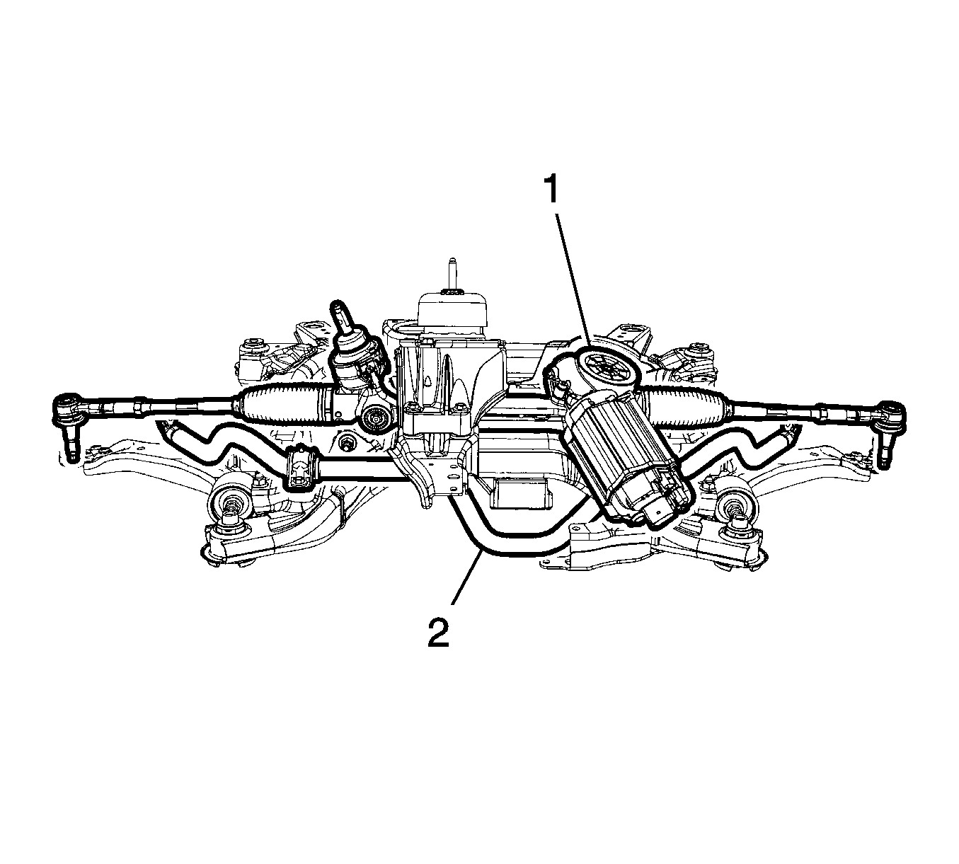
- Raise the vehicle off of the frame with the power steering rack (1) and stabilizer bar still attached the frame.
Danger: Always perform the High Voltage Disabling procedure prior to servicing any High Voltage component or connection. Personal Protection Equipment (PPE) and proper procedures must be followed.
The High Voltage Disabling procedure will perform the following tasks:| • | Identify how to disable high voltage. |
| • | Identify how to test for the presence of high voltage. |
| • | Identify condition under which high voltage is always present and personal protection equipment (PPE) and proper procedures must be followed. |


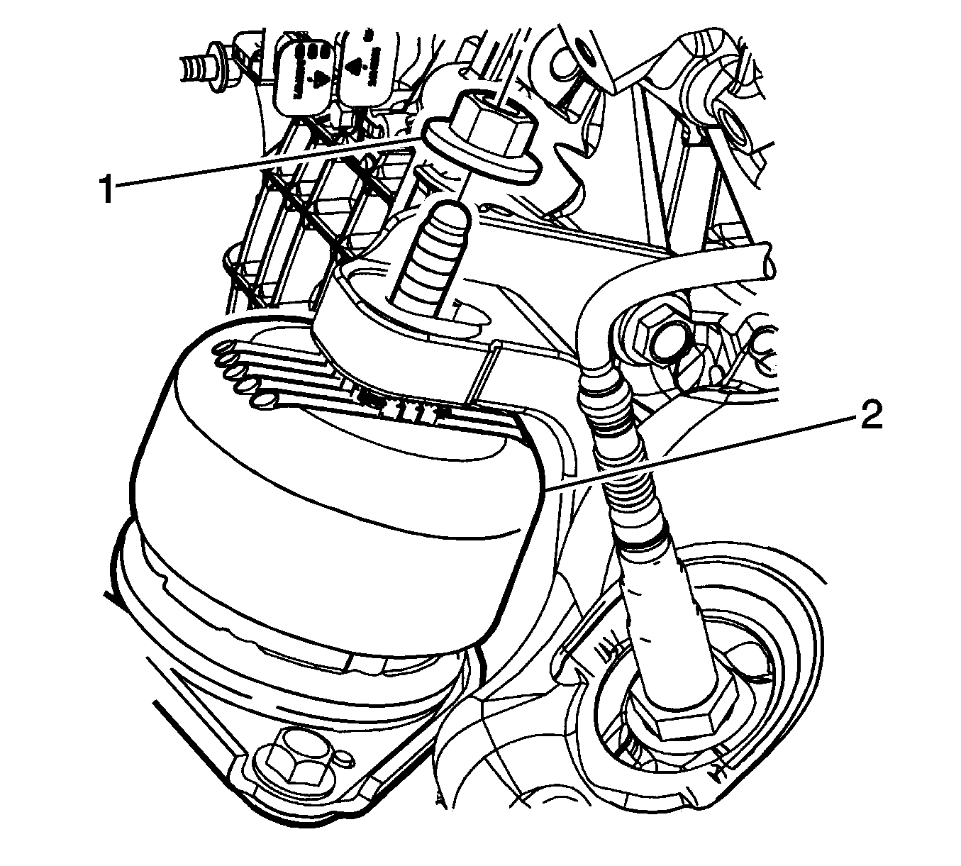
Note: Access the nut through the right hand wheel opening.
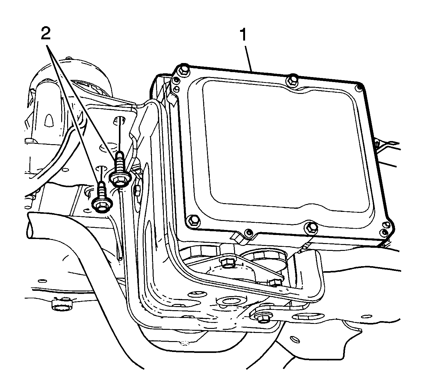
Note: Support the EBCM with mechanics wire to the vehicle underbody.


Installation Procedure
- Lower the vehicle on to the frame.
- Install the front frame bolts, then tighten the bolts to 155 N·m (114 lb ft).
- Install the frame reinforcements. Refer to Drivetrain and Front Suspension Frame Reinforcement Replacement.
- Raise the vehicle off of the J 39580 .
- Install the rear transmission mount to bracket retaining nut, then tighten the nut to 100 N·m (74 lb ft).
- Install the front transmission mount to frame retaining bolts (1), then tighten the bolts to 76 N·m (56 lb ft).
- Install the steering shaft coupling (1) to the steering gear. Refer to Steering Shaft Coupling Replacement.
- Install the four EBCM bolts, then tighten the bolts to 40 N·m (30 lb ft)
- Connect the two electric power steering rack electrical connectors (1,2).
- Install the steering gear electric motor ground strap to the underbody.
- Install the lower ball joints to the steering knuckles. Refer to Lower Control Arm Replacement.
- Connect both left and right stabilizer links. Refer to Stabilizer Shaft Insulator Replacement.
- Connect the outer tie rod ends to the steering knuckle. Refer to Steering Linkage Outer Tie Rod Replacement
- Install the front catalytic converters. Refer to Catalytic Converter Replacement - Left Side and Catalytic Converter Replacement - Right Side.
- Install the air deflector to the frame. Refer to Front Bumper Fascia Air Deflector Replacement.
- Install the engine splash shields. Refer to Engine Splash Shield Replacement.
- Install the tire and wheel assemblies. Refer to Tire and Wheel Removal and Installation.
- Remove the engine support fixture. Refer to Engine Support Fixture
- Release the radiator, air conditioning condenser, and fan module assembly from the upper tie bar.
- Install the front compartment sight shield. Refer to Front Compartment Sight Shields Replacement.
- Enable the hybrid high voltage system. Refer to High Voltage Enabling
- Connect the 12 volt battery negative cable. Refer to Battery Negative Cable Disconnection and Connection
- Check the wheel alignment. Refer to Wheel Alignment Measurement.

Caution: Refer to Fastener Caution in the Preface section.


Frame Replacement 4T45-E Transmission
Special Tools
J 39580 Engine Support Table
Removal Procedure
- Remove the front compartment sight shield. Refer to Front Compartment Sight Shields Replacement.
- Secure the radiator, air conditioning condenser, and fan module assembly to the upper tie bar to keep the assembly with the vehicle when the frame is removed.
- Install the engine support fixture. Refer to Engine Support Fixture.
- Raise and support the vehicle. Refer to Lifting and Jacking the Vehicle.
- Remove the tire and wheel assemblies. Refer to Tire and Wheel Removal and Installation.
- Remove the engine splash shields. Refer to Engine Splash Shield Replacement.
- Remove the two push pins securing the front bumper air deflector to the frame. Refer to Front Bumper Fascia Air Deflector Replacement.
- Remove both left and right stabilizer shaft insulator clamps. Refer to Stabilizer Shaft Insulator Replacement.
- Remove the lower ball joints from the steering knuckles. Refer to Lower Control Arm Replacement.
- Disconnect the steering shaft coupling from the steering gear. Refer to Steering Shaft Coupling Replacement.
- Remove the power steering gear mounting bolts (1) and secure the gear out of the way using mechanic's wire or equivalent. Refer to Steering Gear Replacement.
- Remove the front transmission mount thru bolt.
- Remove the rear transmission mount bolts from the frame.
- Lower the vehicle until the frame contacts the J 39580 .
- Remove the frame reinforcements. Refer to Drivetrain and Front Suspension Frame Reinforcement Replacement.
- Remove the front frame bolts.
- Raise the vehicle off of the frame.
- If replacing the frame, remove the lower control arms. Refer to Lower Control Arm Replacement.


Note: Whenever the steering gear is moved in relation to the body, disconnect the intermediate shaft from the steering gear.


Installation Procedure
- If removed, Install the lower control arms. Refer to Lower Control Arm Replacement.
- Lower the vehicle on to the frame.
- Install the front frame bolts.
- Install the frame reinforcement. Refer to Drivetrain and Front Suspension Frame Reinforcement Replacement.
- Raise the vehicle off of the J 39580 .
- Install the rear transmission mount bolts to the frame.
- Install the front transmission mount thru bolt.
- Install the power steering gear mounting bolts (1). Refer to Steering Gear Replacement.
- Install the steering shaft coupling to the steering gear. Refer to Steering Shaft Coupling Replacement.
- Install the lower ball joints to the steering knuckles. Refer to Lower Control Arm Replacement.
- Install both left and right stabilizer shaft insulator clamps. Refer to Stabilizer Shaft Insulator Replacement.
- Install the two push pins securing the front bumper air deflector to the frame. Refer to Front Bumper Fascia Air Deflector Replacement.
- Install the engine splash shields. Refer to Engine Splash Shield Replacement.
- Install the tire and wheel assemblies. Refer to Tire and Wheel Removal and Installation.
- Remove the engine support fixture. Refer to Engine Support Fixture.
- Release the radiator, air conditioning condenser, and fan module assembly from the upper tie bar.
- Install the front compartment sight shield. Refer to Front Compartment Sight Shields Replacement.
- Check the wheel alignment. Refer to Wheel Alignment Measurement.

Caution: Refer to Fastener Caution in the Preface section.

Tighten
Tighten the bolts to 155 N·m (114 lb ft).


Tighten
Tighten the bolts to 50 N·m (37 lb ft).

Tighten
Tighten the bolt to 110 N·m (81 lb ft).


Frame Replacement 6T70 Transmission
Special Tools
J 39580 Engine Support Table
Removal Procedure
- Remove the front compartment sight shield. Refer to Front Compartment Sight Shields Replacement.
- Secure the radiator, air conditioning condenser, and fan module assembly to the upper tie bar to keep the assembly with the vehicle when the frame is removed.
- Install the engine support fixture. Refer to Engine Support Fixture for the 3.5 L LZ4 engine or Engine Support Fixture for the 3.6 L LY7 engine.
- Raise and support the vehicle. Refer to Lifting and Jacking the Vehicle.
- Remove the tire and wheel assemblies. Refer to Tire and Wheel Removal and Installation.
- Remove the engine splash shields. Refer to Engine Splash Shield Replacement.
- Remove the two push pins securing the front bumper air deflector to the frame. Refer to Front Bumper Fascia Air Deflector Replacement.
- Remove the catalytic converters. Refer to Catalytic Converter Replacement - Left Side and Catalytic Converter Replacement - Right Side.
- Remove the propeller shaft if the vehicle is equipped with AWD. Refer to Propeller Shaft Replacement.
- Remove both left and right stabilizer shaft insulator clamps. Refer to Stabilizer Shaft Insulator Replacement.
- Remove the lower ball joints from the steering knuckles. Refer to Lower Control Arm Replacement.
- Disconnect the steering shaft coupling from the steering gear. Refer to Steering Shaft Coupling Replacement.
- Remove the power steering gear mounting bolts (1) and secure the gear out of the way using mechanics wire or equivalent. Refer to Steering Gear Replacement.
- Remove the front transmission mount thru bolt.
- Remove the rear transmission mount bolts from the frame.
- Lower the vehicle until the frame contacts the J 39580 .
- Remove the frame reinforcements. Refer to Drivetrain and Front Suspension Frame Reinforcement Replacement.
- Remove the front frame bolts.
- Raise the vehicle off of the frame.
- If replacing the frame, remove the lower control arms. Refer to Lower Control Arm Replacement.


Note: Whenever the steering gear is moved in relation to the body, disconnect the intermediate shaft from the steering gear.


Installation Procedure
- If removed, install the lower control arms. Refer to Lower Control Arm Replacement.
- Lower the vehicle on to the frame.
- Install the front frame bolts.
- Install the frame reinforcement. Refer to Drivetrain and Front Suspension Frame Reinforcement Replacement.
- Raise the vehicle off of the J 39580 .
- Install the rear transmission mount bolts to the frame.
- Install the front transmission mount thru bolt.
- Install the power steering gear mounting bolts (1). Refer to Steering Gear Replacement.
- Install the steering shaft coupling to the steering gear. Refer to Steering Shaft Coupling Replacement.
- Install the lower ball joints to the steering knuckles. Refer to Lower Control Arm Replacement.
- Install the propeller shaft if the vehicle is equipped with AWD. Refer to Propeller Shaft Replacement.
- Install the catalytic converters. Refer to Catalytic Converter Replacement - Left Side and Catalytic Converter Replacement - Right Side.
- Install both left and right stabilizer shaft insulator clamps. Refer to Stabilizer Shaft Insulator Replacement.
- Install the two push pins securing the front bumper air deflector to the frame. Refer to Front Bumper Fascia Air Deflector Replacement.
- Install the engine splash shields. Refer to Engine Splash Shield Replacement.
- Install the tire and wheel assemblies. Refer to Tire and Wheel Removal and Installation.
- Remove the engine support fixture. Refer to Engine Support Fixture for the 3.5 L LZ4 engine or Engine Support Fixture for the 3.6 L LY7 engine.
- Release the radiator, air conditioning condenser, and fan module assembly from the upper tie bar.
- Install the front compartment sight shield. Refer to Front Compartment Sight Shields Replacement.
- Check the wheel alignment. Refer to Wheel Alignment Measurement.

Caution: Refer to Fastener Caution in the Preface section.

Tighten
Tighten the bolts to 155 N·m (114 lb ft).


Tighten
Tighten the bolts to 50 N·m (37 lb ft).

Tighten
Tighten the bolt to 110 N·m (81 lb ft).


