Steering Angle Sensor Replacement Two Mode Hybrid
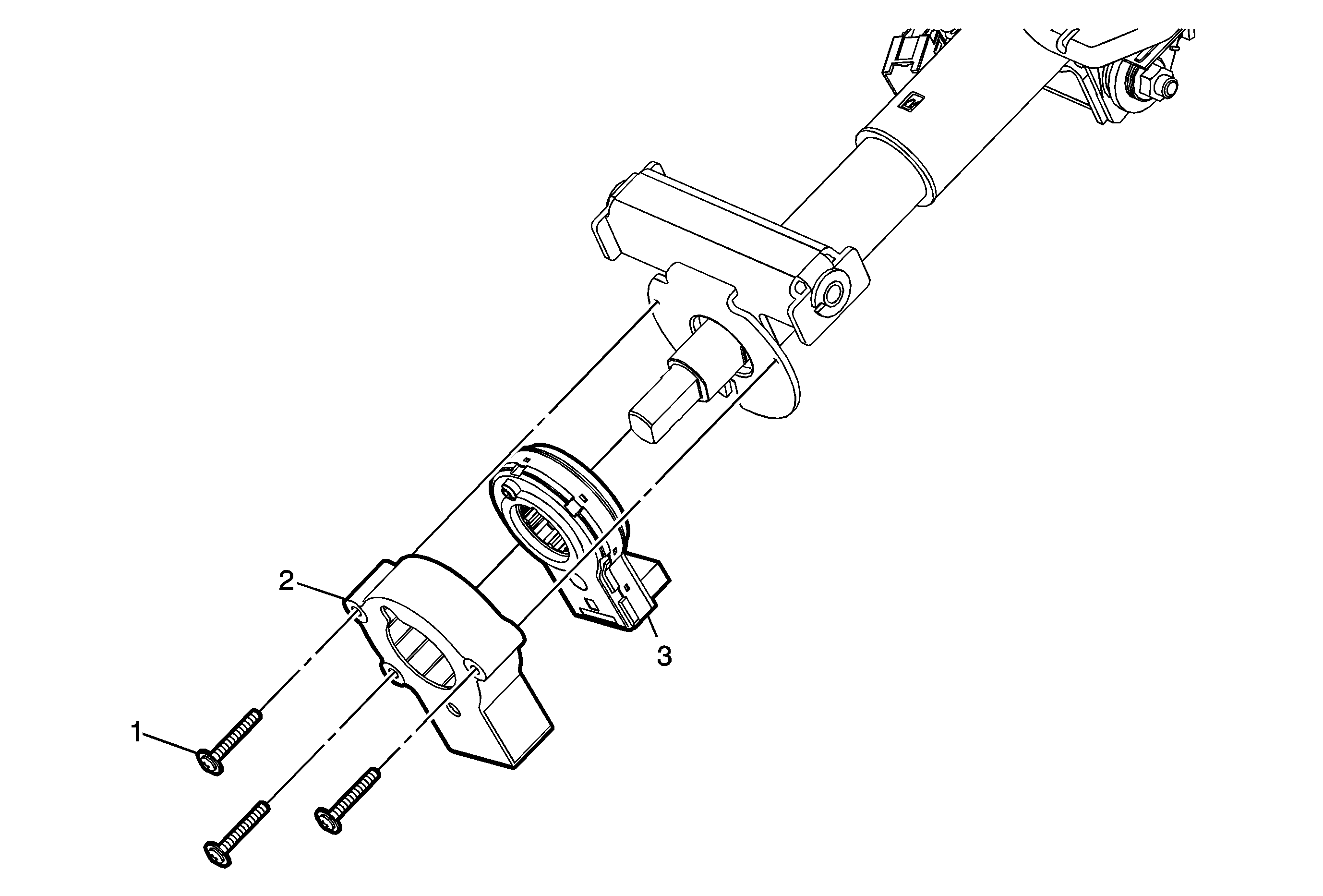
Callout | Component Name |
|---|---|
Preliminary ProcedureRemove the steering column. Refer to Steering Column Replacement. | |
1 | Steering Angle Sensor Cover Bolt (Qty: 3) |
2 | Steering Angle Sensor Cover |
3 | Steering Angle Sensor Procedure
|
Steering Angle Sensor Replacement Hydraulic Power Steering
Removal Procedure
- Turn the steering wheel to the straight-ahead position and secure the steering wheel.
- Disconnect the negative battery cable. Refer to Battery Negative Cable Disconnection and Connection.
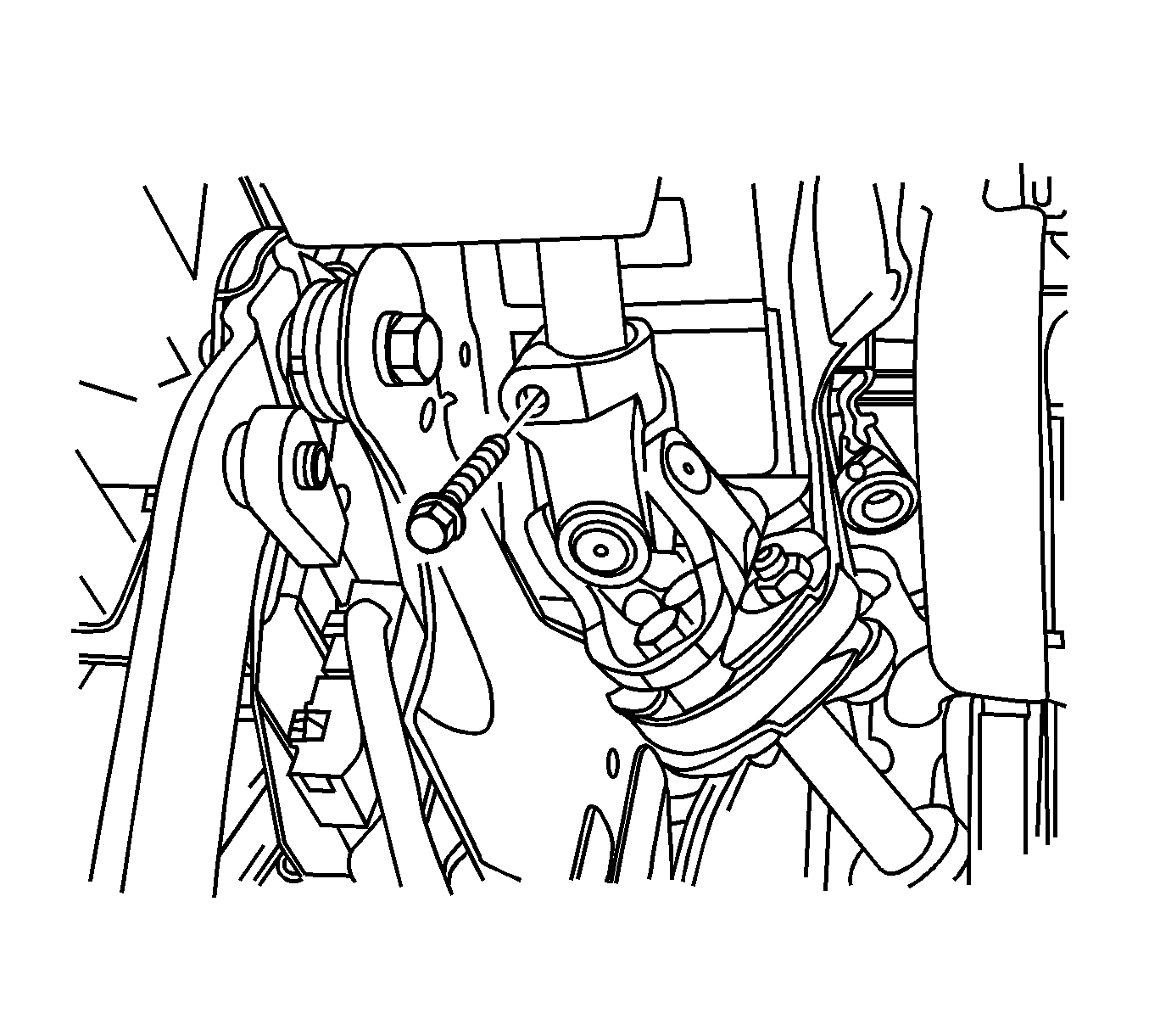
- Use paint in order to place match marks on the steering shaft coupling and on the lower portion of the steering column shaft.
- Remove the upper pinch bolt.
- Separate the steering shaft coupling from the steering column shaft.
- Disconnect the connector from the steering angle sensor.
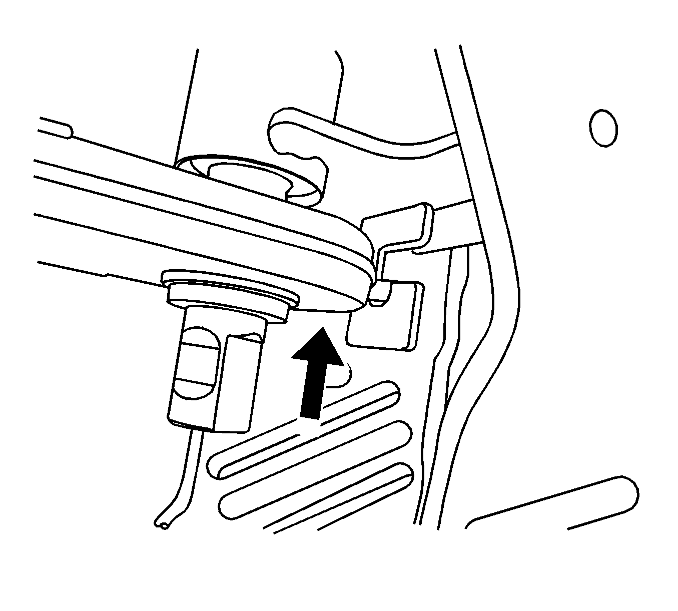
- Move the steering angle sensor up the steering column shaft toward the steering wheel.
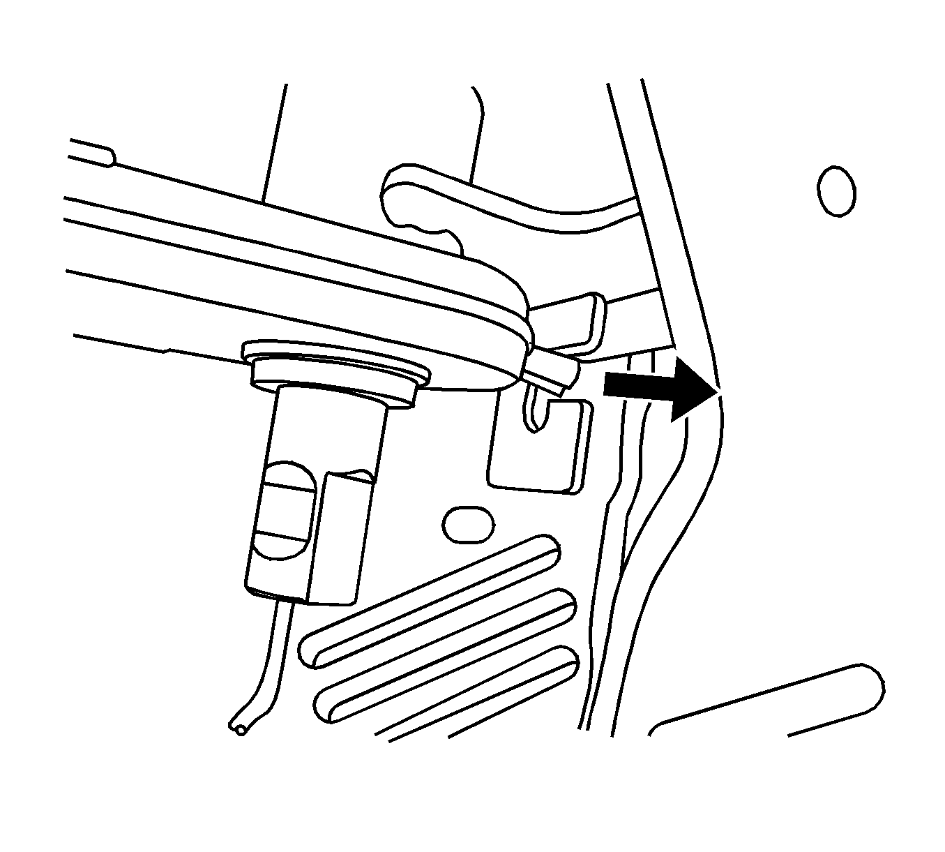
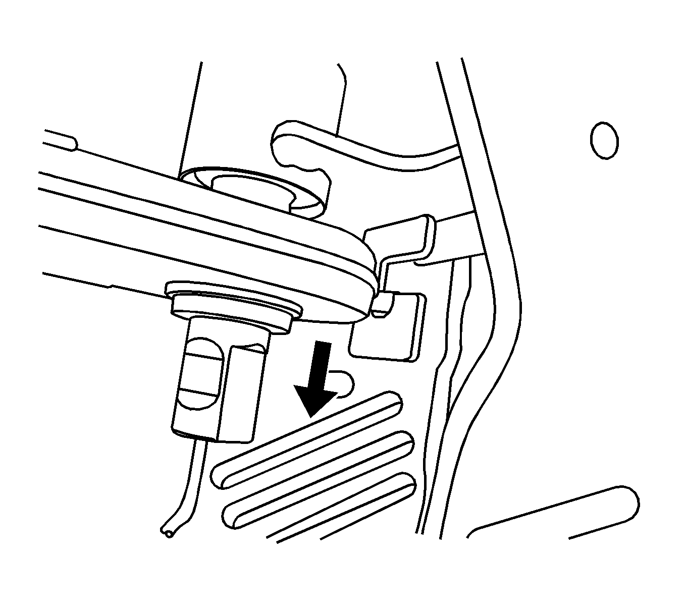
- Remove the steering angle sensor by turning the sensor out of the retaining bracket slot and sliding the sensor down the steering column shaft.
Notice: Secure the steering wheel utilizing a strap to prevent rotation. Locking of the steering column will prevent damage and a possible malfunction of the SIR system. The steering wheel must be secured
in position before disconnecting the following components:
• The steering column • The intermediate shaft • The steering gear
Installation Procedure
- Slide the steering angle sensor up the steering column shaft until the sensor is on the retaining bracket slot.
- Install the steering angle sensor into the groove of the retaining bracket.
- Connect the connector to the steering angle sensor.
- Align the match marks and carefully guide the steering shaft coupling onto steering column shaft.
- Install the pinch bolt into the steering shaft coupling.
- Connect the negative battery cable. Refer to Battery Negative Cable Disconnection and Connection.
- Perform the steering angle sensor centering procedure. Refer to Steering Angle Sensor Centering.

Important: Ensure the steering wheel is in the straight-ahead position.
Notice: Refer to Fastener Notice in the Preface section.
Tighten
Tighten the bolt to 30 N·m (22 lb ft).
