Ignition Lock Cylinder Replacement With Electronic Power Steering
Removal Procedure
- Remove the wipers/washer switch. Refer to Windshield Wiper and Washer Switch Replacement
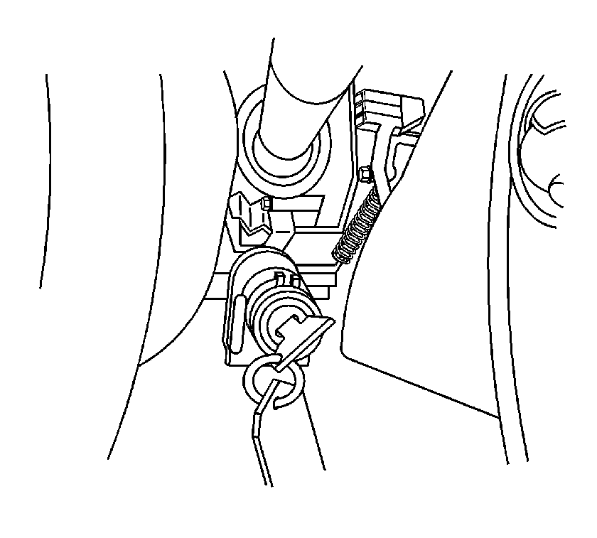
- Turn the ignition lock cylinder to the RUN position.
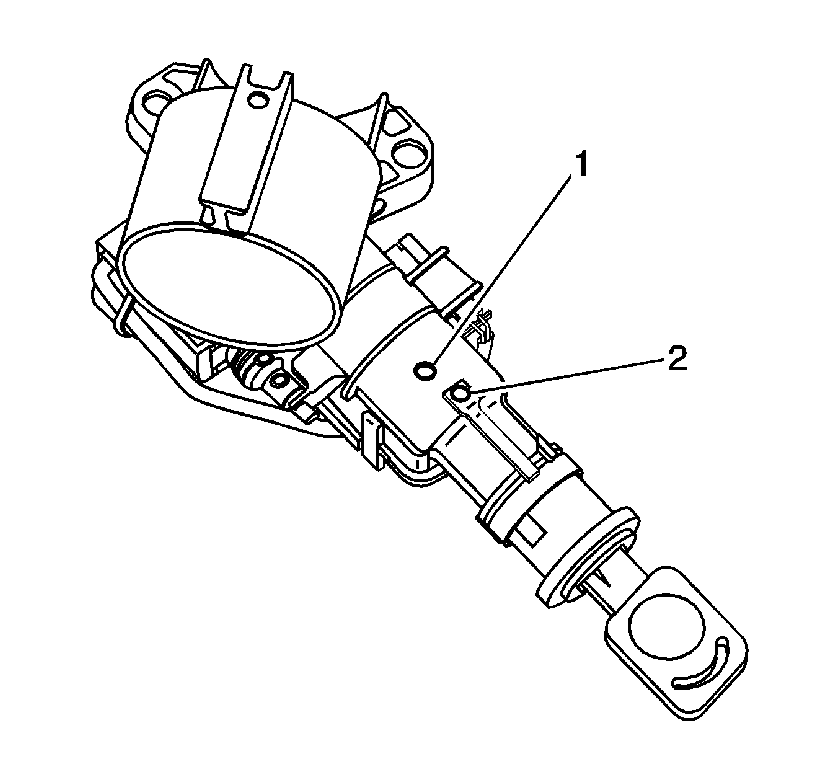
- Depress the first retaining tab through the ignition/start switch housing front access hole (2) with a small allen wrench or similar pick-type tool. The ignition lock cylinder will back out slightly.
- Depress the second retaining tab through the ignition/start switch housing rear access hole (1). The ignition lock cylinder will back out slightly again.
- Pull the ignition lock cylinder out enough to locate the second retaining tab in the ignition/start switch housing front access hole (2) and depress it.
- Pull and the ignition lock cylinder should release from the ignition/start switch housing. The ignition lock cylinder may have to be wiggled while pulling to release it from the ignition/start switch housing.

Important: There are two retaining tabs on the ignition lock cylinder. Both will need to be manipulated to remove it from the ignition/start switch housing.
Installation Procedure
- Position the ignition lock cylinder in the run position and insert it into the ignition/start switch housing.
- Rotate the ignition lock cylinder in the housing and verify proper rotation.
- Install the wipers/washer switch. Refer to Windshield Wiper and Washer Switch Replacement

Important: If you are installing a new ignition lock cylinder, refer to Key and Lock Cylinder Coding .
Ignition Lock Cylinder Replacement With Hydraulic Power Steering

Callout | Component Name |
|---|---|
Preliminary Procedures
| |
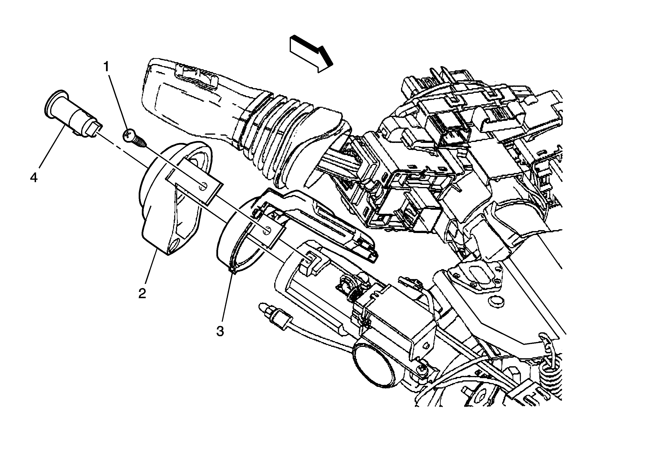
1 | Ignition Lock Cylinder Bolt Notice: Refer to Fastener Notice in the Preface section. Tighten |
2 | Ignition Lock Cylinder Bezel ProcedureDisengage the ignition lock cylinder bezel light from the bezel. |
3 | Theft Deterrent Module ProcedureDisconnect any electrical connectors as needed. |
4 | Ignition Lock Cylinder Procedure
Tip |
Ignition Lock Cylinder Replacement With Electronic Power Steering
Removal Procedure
- Remove the windshield wiper and washer switch. Refer to Windshield Wiper and Washer Switch Replacement.
- Turn the ignition lock cylinder to the RUN position.
- Depress the first retaining tab through the ignition and start switch housing front access hole (2) with a small allen wrench or similar pick-type tool. The ignition lock cylinder will back out slightly.
- Depress the second retaining tab through the ignition and start switch housing rear access hole (1). The ignition lock cylinder will back out slightly again.
- Pull the ignition lock cylinder out enough to locate the second retaining tab in the ignition and start switch housing front access hole (2) and depress it.
- Pull and the ignition lock cylinder should release from the ignition and start switch housing. The ignition lock cylinder may have to be wiggled while pulling to release it from the ignition and start switch housing.
- If you are installing a new ignition lock cylinder, refer to Key and Lock Cylinder Coding.

Note: There are two retaining tabs on the ignition lock cylinder. Both will need to be manipulated in order to remove it from the ignition and start switch housing.
Installation Procedure
- Position the ignition lock cylinder in the run position and insert it into the ignition and start switch housing.
- Rotate the ignition lock cylinder in the ignition and start switch housing and verify proper rotation.
- Install the windshield wiper and washer switch. Refer to Windshield Wiper and Washer Switch Replacement.

Ignition Lock Cylinder Replacement With Hydraulic Power Steering

Callout | Component Name |
|---|---|
Preliminary Procedures
| |
1 | Ignition Lock Cylinder Bolt Caution: Refer to Fastener Caution in the Preface section. Tighten |
2 | Ignition Lock Cylinder Bezel ProcedureDisengage the ignition lock cylinder bezel light from the bezel. |
3 | Theft Deterrent Module ProcedureDisconnect any electrical connectors as needed. |
4 | Ignition Lock Cylinder Procedure
|
