For 1990-2009 cars only
Removal Procedure
- Disconnect the negative battery cable. Refer to Battery Negative Cable Disconnection and Connection.
- Remove the quarter lower rear trim panel. Refer to Quarter Lower Rear Trim Panel Replacement.
- Remove the center pillar lower garnish molding. Refer to Center Pillar Lower Garnish Molding Replacement.
- Remove the front carpet retainer. Refer to Front Side Door Opening Floor Carpet Retainer Replacement.
- Remove the generator battery control module cover. Refer to Generator Control Module Cover Replacement.
- Remove the engine cover. Refer to Fuel Injector Sight Shield Replacement.
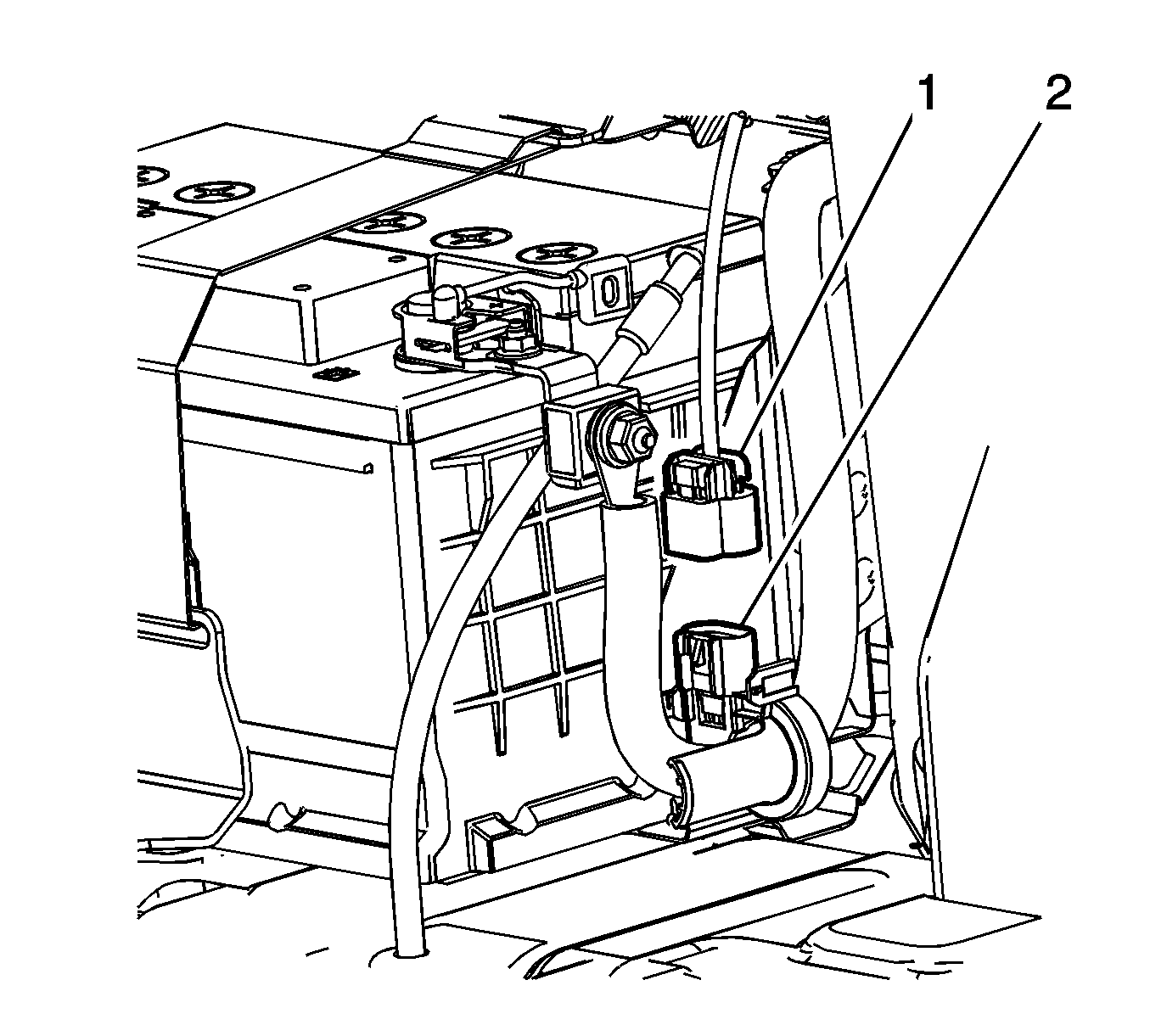
- Disconnect the current sensor harness connector (1).
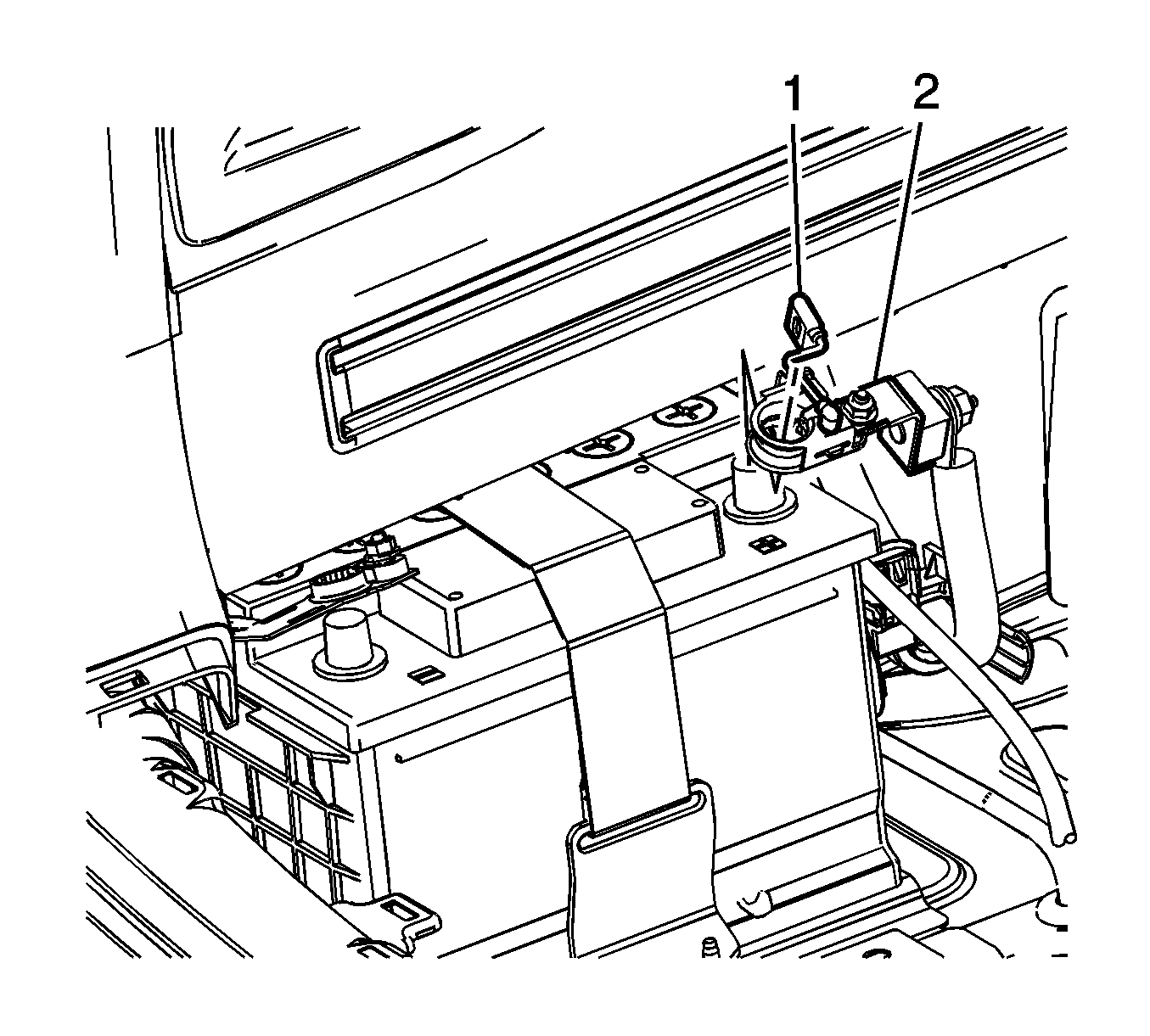
- Rotate the positive cable terminal lever (1) to the release position.
- Remove the positive battery cable terminal (2) from the battery.
- Note the routing of the positive battery cable through the chassis.
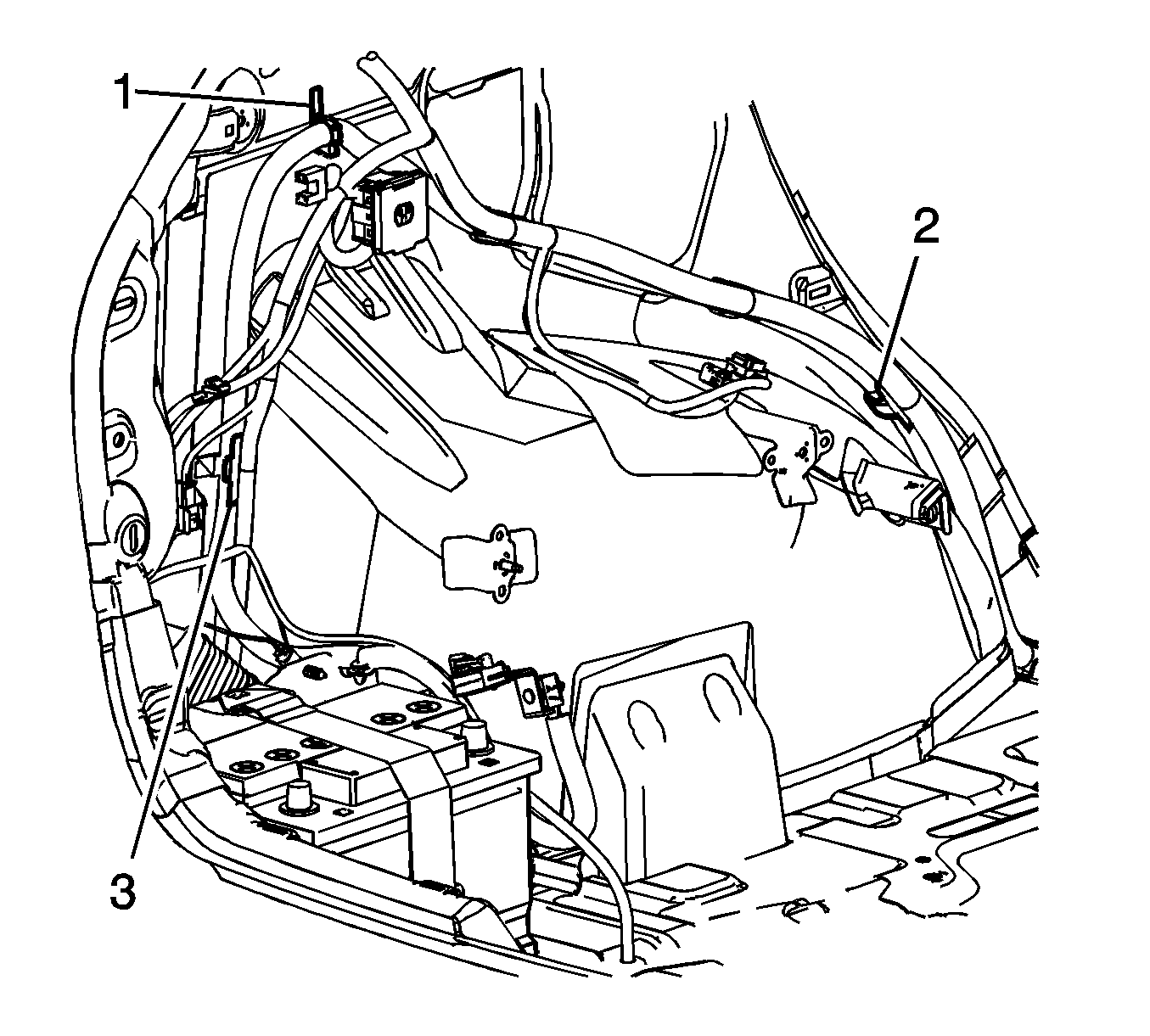
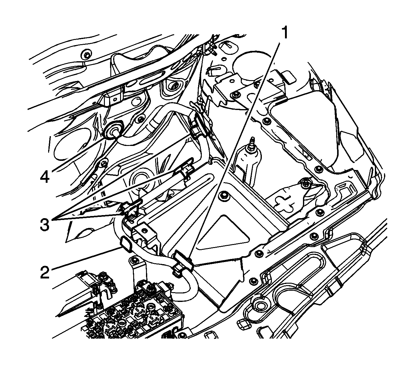
- Disengage the positive battery cable from the retainers (1, 2, and 3).
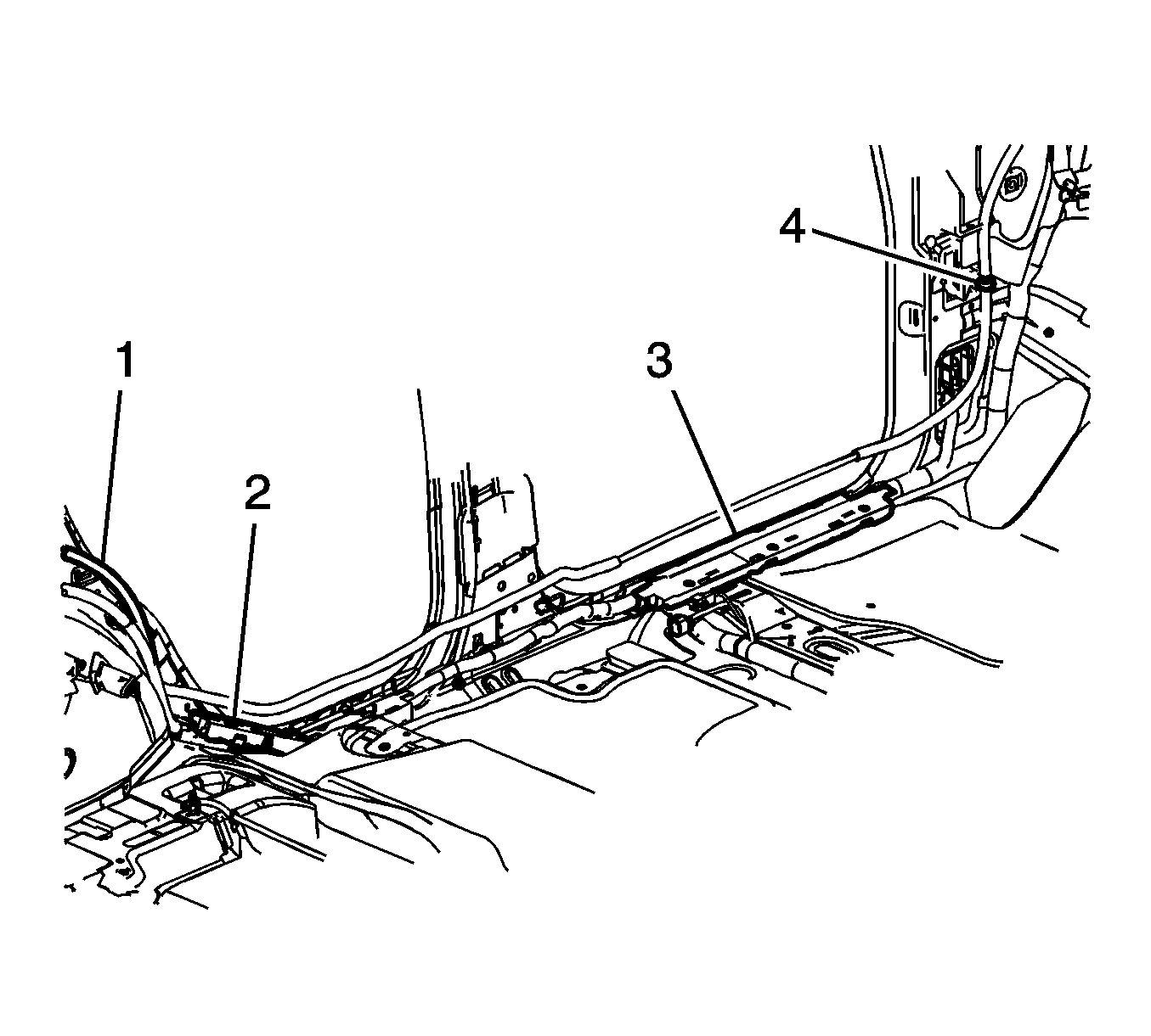
- Disengage the positive battery cable from the retainers (1, 2, 3, and 4).
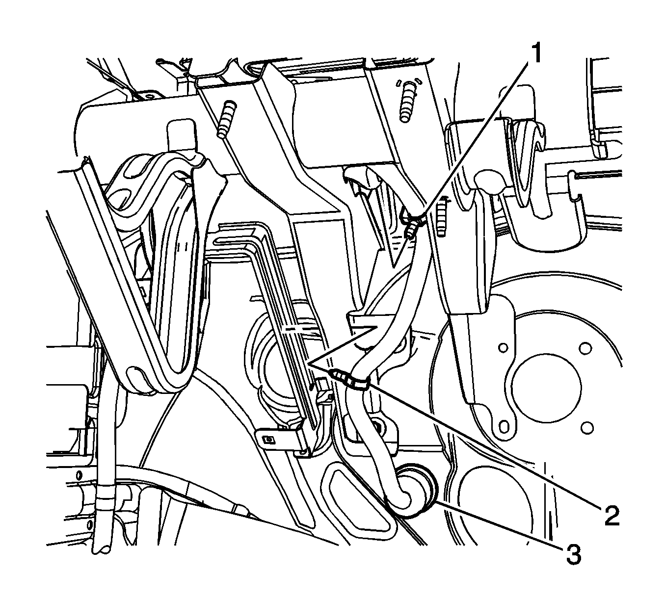
- From under the dash, disengage the retainers (1 and 2).
- Disengage the positive cable grommet (3) from the dash panel reinforcement.
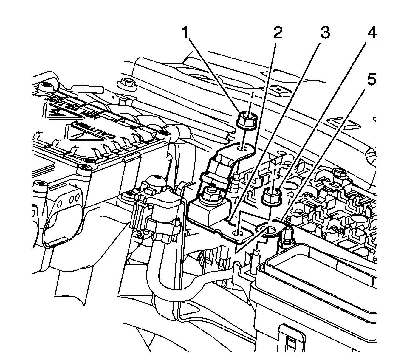
- Remove the under hood fuse box and junction block covers.
- Remove the terminal fasteners (1, and 4).
- Remove the fused cable (3) from the terminal.
- Remove the cables (2 and 5) from the terminals.
- Disengage the push retainers (1 and 3) from the hybrid control module tray.
- Remove the positive battery cable from the retainers (2 and 4).
- Route the cable through the dash panel reinforcement to inside the vehicle.
- Remove the Positive battery cable from inside the vehicle.
Installation Procedure
- Route the positive battery cable as noted in the removal.
- Route the cable through the dash panel reinforcement to under the hood.
- Install the positive battery cable from the retainers (2 and 4).
- Install the push retainers (1 and 3) into the hybrid control module tray.
- Route the cables (2 and 5) to the terminals.
- Install the fused cable (3) to the terminal.
- Install the terminal fasteners (1, and 4) and tighten to 10 N·m (89 lb in)..
- Install the under hood fuse box and junction block covers.
- Install the positive cable grommet (3) into the dash panel reinforcement.
- From under the dash, attach the retainers (1 and 2).
- Install the positive battery cable into the retainers (1, 2, 3, and 4).
- Install the positive battery cable into the retainers (1, 2, and 3).
- Position the positive battery cable terminal (2) to the battery.
- Rotate the positive cable terminal lever (1) to the locked position.
- Connect the current sensor harness connector (1).
- Install the fuel injection sight shield. Refer to Fuel Injector Sight Shield Replacement.
- Install the generator battery control module cover. Refer to Generator Control Module Cover Replacement.
- Install the center pillar lower garnish molding. Refer to Center Pillar Lower Garnish Molding Replacement.
- Install the quarter lower rear trim panel. Refer to Quarter Lower Rear Trim Panel Replacement.
- Connect the negative battery cable. Refer to Battery Negative Cable Disconnection and Connection.


Caution: Refer to Fastener Caution in the Preface section.


