IGNITION KEY STICKS IN LOCK CYLINDER (REMOVE CASTING BURR)

Subject: IGNITION KEY STICKS IN THE LOCK CYLINDER
Model and Year: 1991 CAVALIER ONLY
DESCRIPTION:
------------ 1991 Cavalier models equipped with a floor shift automatic transaxle use a Park Lock System. This system uses a park lock cable which is attached to the floor shift lever at one end, and the column mounted lock cylinder housing assembly at the other end. Under certain circumstances, the vehicle operator may experience a situation where the ignition key sticks in the ignition lock cylinder. Vehicles involved are as follows:
Janesville Plant. Start of production through MJ132664. Lordstown Plant. Start of production through M7129428.
SYSTEM CHECK PROCEDURE:
Use the following procedure to check the Park Lock System and verify that the ignition key cannot be removed from the lock cylinder.
1. Place shifter in the "Park" position and turn ignition key to the "Off Lock" position.
The key should be able to be removed, if you are not able to turn the key to "Off Lock" and remove the key, refer to Condition "A."
2. Check and make sure that the shifter cannot be moved from the "Park" position by depressing the shifter button and attempting to actuate the shift assembly.
The shifter should not shift from park. If able to shift, refer to Condition "A."
3. Turn ignition key to the "Run" position. 4. Move the shifter to the "Neutral" position. 5. Turn ignition key to the "Off Lock" position.
The ignition key rotation should stop before reaching the "Off Lock" position and the key cannot be removed from lock cylinder. If key is removable, refer to Condition "A."
6. With the key in the same position (before reaching "Off Lock") return the shifter to the "Park" position.
7. Turn the ignition key towards the "Run" position, then to the "Off Lock" position and remove the key.
8. Replace key in the ignition lock cylinder.
The Park Lock System is operating properly if all of the above steps can be completed correctly. If the ignition key still sticks in the ignition lock cylinder, go to Condition "B" below.
CONDITION A:
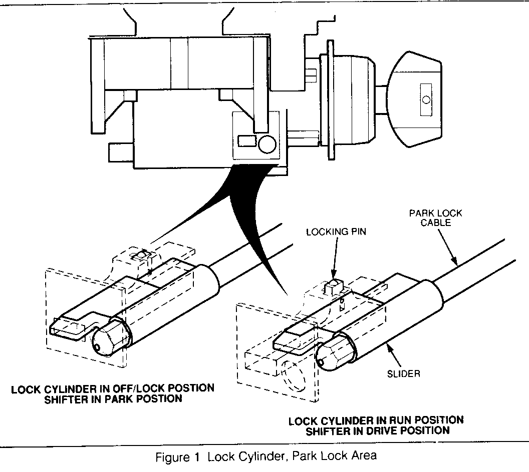
When the shift lever is shifted to "Park," the park lock cable slider is loaded against the locking pin in the lock cylinder housing assembly. (See Figure 1). This loading prevents the park lock cable slider from extending to its full "Park" position. The lock cylinder is prevented from being rotated to its "Off Lock" position. The vehicle operator cannot remove the ignition key from the lock cylinder assembly.
CAUSE A:
A misadjusted park lock cable at the shifter assembly end.
CORRECTION A:
1. Refer to the vehicle service manual for disassembly of the console.
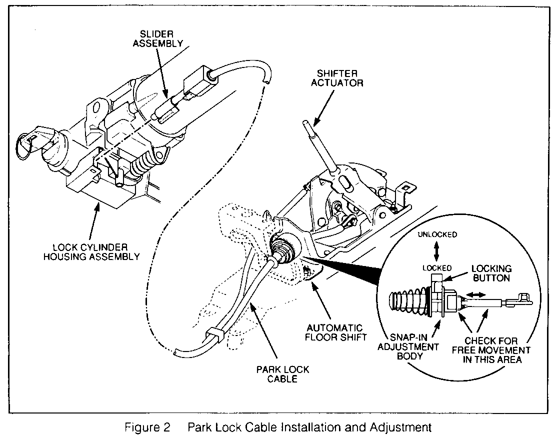
2. With the shift lever in "Park," move the locking button on the shifter end of the park lock cable to the "Unlock" position. (See Figure 2).
3. Turn the ignition key to the "Off Lock" position and remove the key. If you are not able to remove the key, depress the shifter actuator and make sure that the adjustment body moves freely within the snap-in adjustment body. (See Figure 2) Note: Key should be able to turn to the "Off Lock" position and be removed.
4. Depress and release shifter actuator.
5. Move the locking button on the shifter end of the park lock cable to the "Lock" position. (See Figure 2).
6. Perform the system check again by following steps 1 through 8 in the "System Check Procedure."
Note: If the key cannot be removed, refer to "Condition B."
CONDITION B:
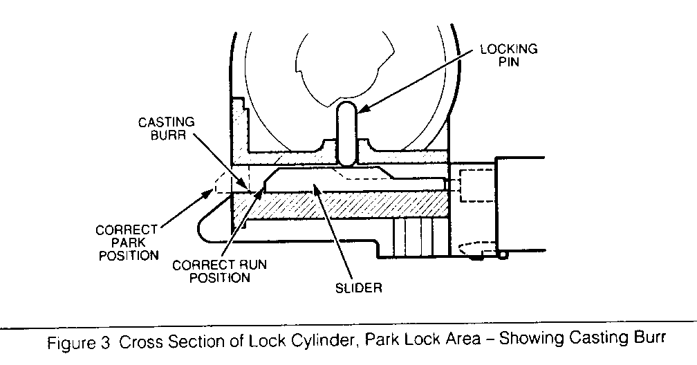
When the shift lever is shifted to "Park," the park lock cable slider catches on a casting burr (sharp edge) in the lock cylinder housing assembly. This prevents the park lock cable slider from extending to its full "Park" position. The lock cylinder is prevented from being rotated to its "Off Lock" position. The vehicle operator cannot remove the ignition key from the lock cylinder assembly.
CAUSE B:
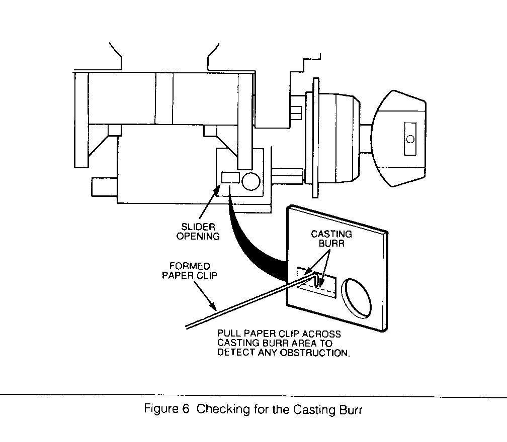
A casting parting line of the lock cylinder housing assembly resulted in a casting burr on the bottom and left side of the rectangular slider opening on the lock cylinder housing. (See Figure 3 and Figure 6).
CORRECTION B:
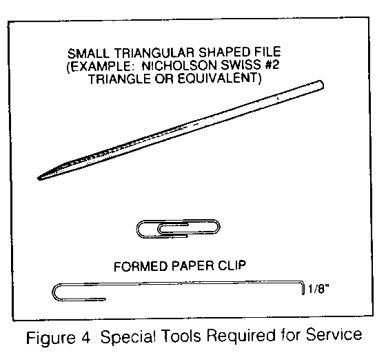
Note: Two special tools are required to correct slider interference: a formed paper clip and a small triangular shaped file. (See Figure 4).
Note: Refer to the vehicle service manual (Sections 3F, 3F1, and 3F2) for detailed disassembly instructions.
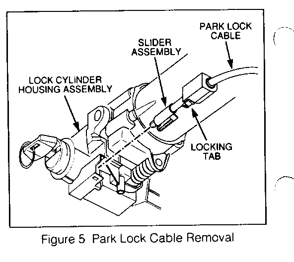
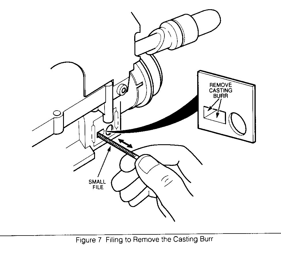
1. Disconnect the negative battery cable. 2. Remove the pad and disconnect the horn lead. 3. Remove the steering wheel retainer and nut. 4. Remove the steering wheel using J 1859-03. 5. Remove tilt lever from the column housing, if so equipped. 6. Remove upper cover screws and upper steering column cover. Note: Make sure that spring clips remain attached to upper cover. 7. Remove key from lock cylinder. 8. Remove lower steering column cover screws and lower steering column cover. 9. Install key in lock cylinder and turn to the "Run" position. 10. Disconnect park lock cable from lock cylinder housing assembly by depressing locking tab with a small screwdriver (See Figure 5). 11. Check for a casting burr by dragging the tip of the preformed paper clip across the bottom and left surface of the park lock cable slider opening to detect any signs of a rough edge. (See Figure 6). 12. Use a small triangular shaped file (Nicholson Swiss #2 Triangle or equivalent) to file down the rough edges of the park lock cable slider opening as shown (See Figure 7). 13. Check that the rough edges are removed by again dragging the tip of the preformed paper clip across the surface of the park lock cable slider opening and feeling for any remaining edges of the casting burr. The end of the paper clip must not detect any sign of the burr. 14. Repeat steps 12 and 13 until all traces of the burr have been removed from the bottom and left sides of the slider opening. 15. From the back side of the slider opening, use compressed air to clean the slider opening in the lock cylinder housing assembly. Make sure that no filings remain to obstruct slider or locking pin movement. 16. Install the park lock cable. Make sure the cable locking tab is firmly seated and latched in the lock cylinder housing slot. 17. Test for proper operation of the park lock system by repeating the check procedure in the "Description" section. 18. Reassemble column in reverse order. Note: Refer to the vehicle service manual for detailed reassembly instructions.
WARRANTY INFORMATION:
Labor Operation Number: T1714 (Adjust and remove burrs) Labor Time: 0.6 hour
Labor Operation Number: K5173 (Park lock cable adjust)
Use applicable labor time guide for labor hours.
Trouble Code: 92
General Motors bulletins are intended for use by professional technicians, not a "do-it-yourselfer". They are written to inform those technicians of conditions that may occur on some vehicles, or to provide information that could assist in the proper service of a vehicle. Properly trained technicians have the equipment, tools, safety instructions and know-how to do a job properly and safely. If a condition is described, do not assume that the bulletin applies to your vehicle, or that your vehicle will have that condition. See a General Motors dealer servicing your brand of General Motors vehicle for information on whether your vehicle may benefit from the information.
