| Figure 1: |
Oil Pump Assembly
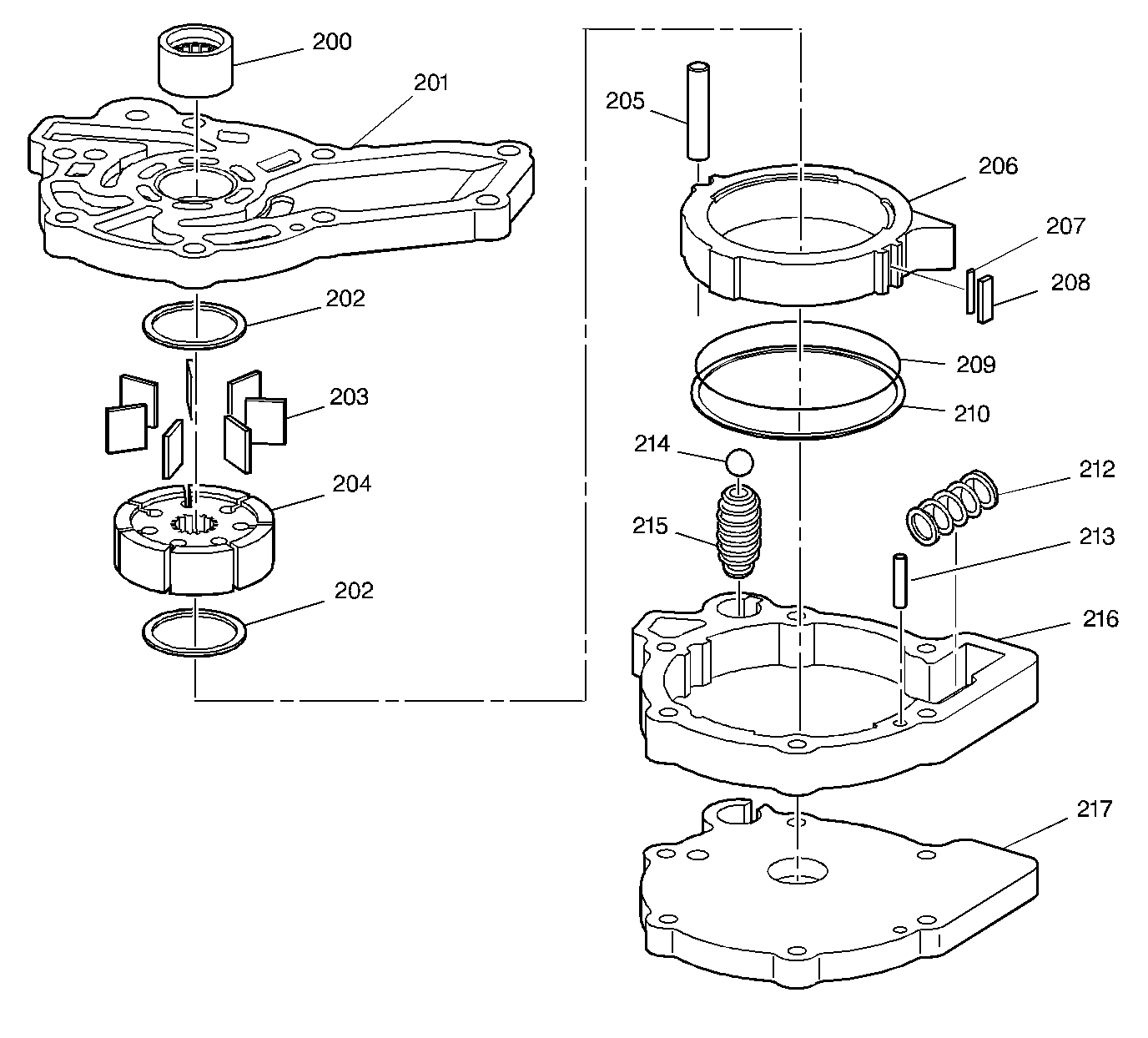
|
| Figure 2: |
Control Valve Body Assembly
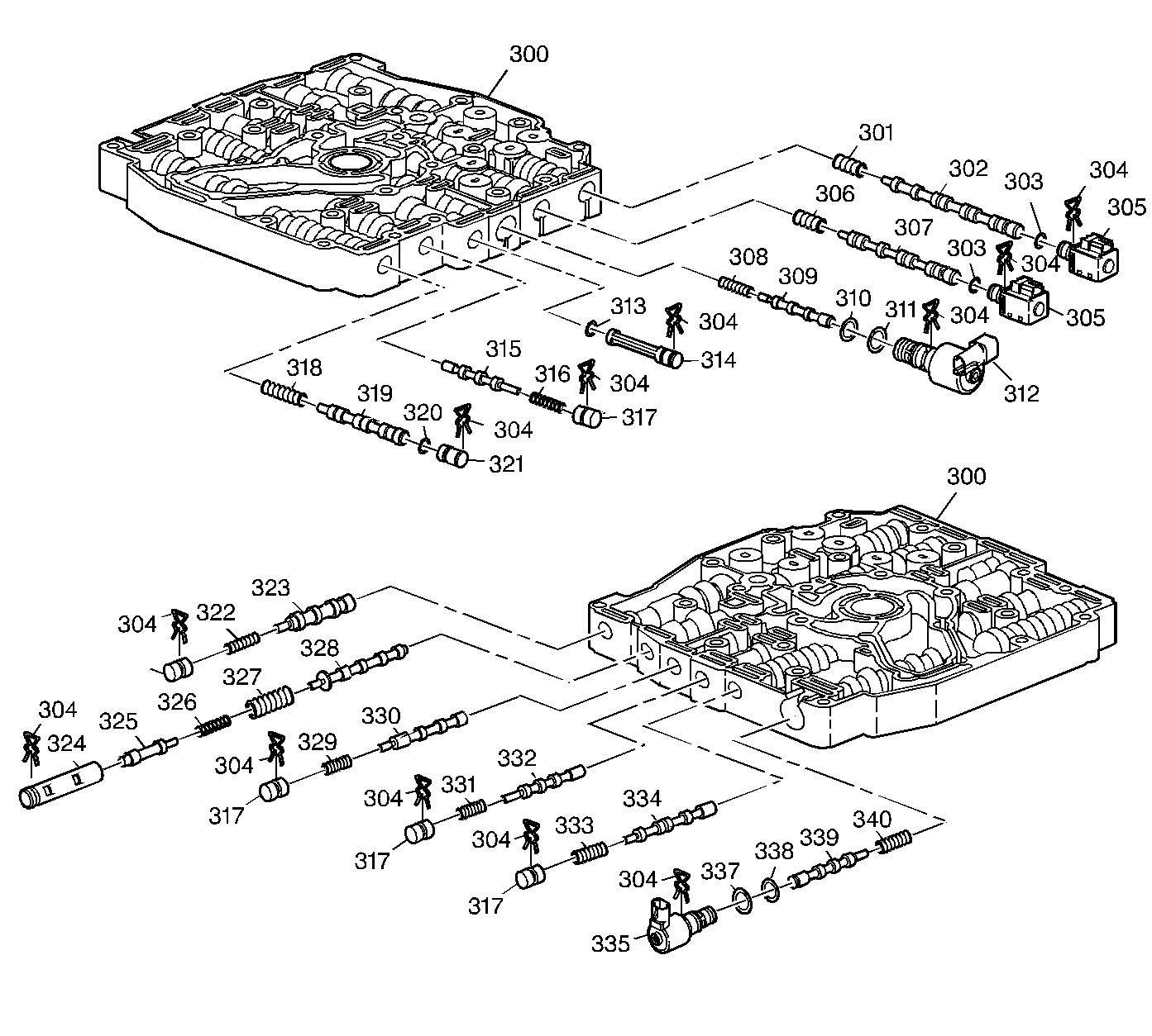
|
| Figure 3: |
Driven Sprocket Support Assembly/2nd Clutch
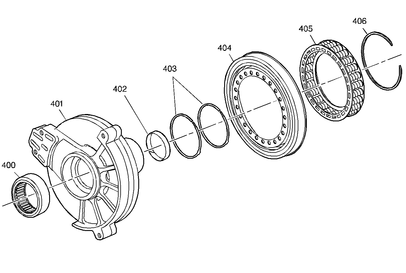
|
| Figure 4: |
Reverse Input Clutch Assembly
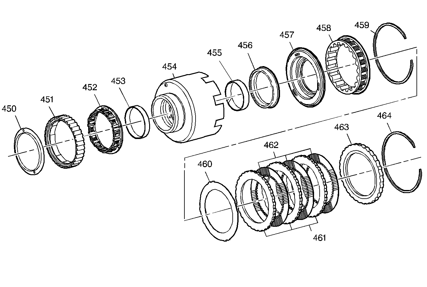
|
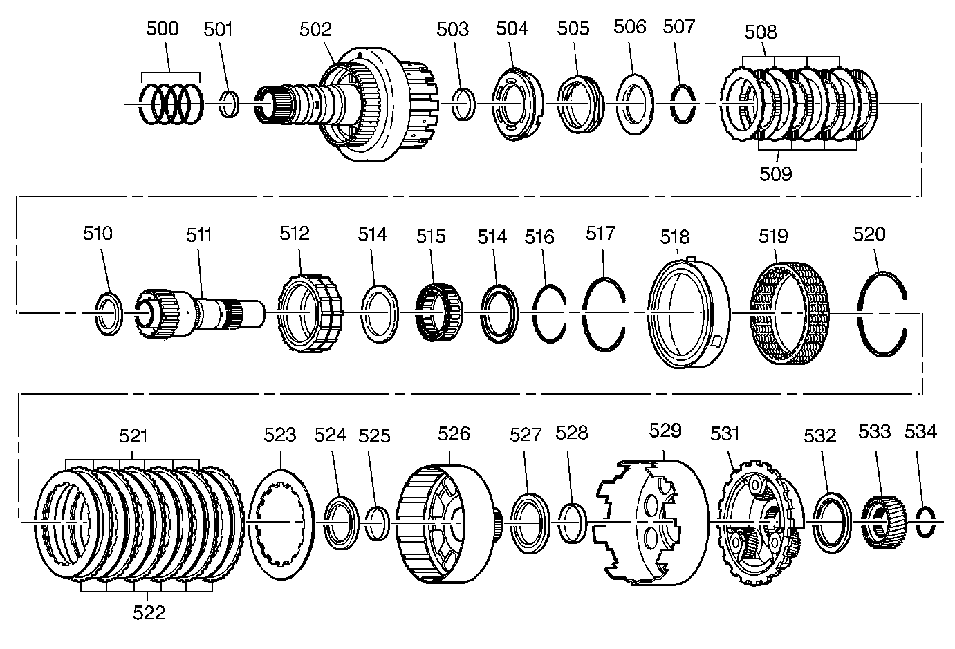
| Figure 5: |
Direct and Coast Clutch Assemblies
|
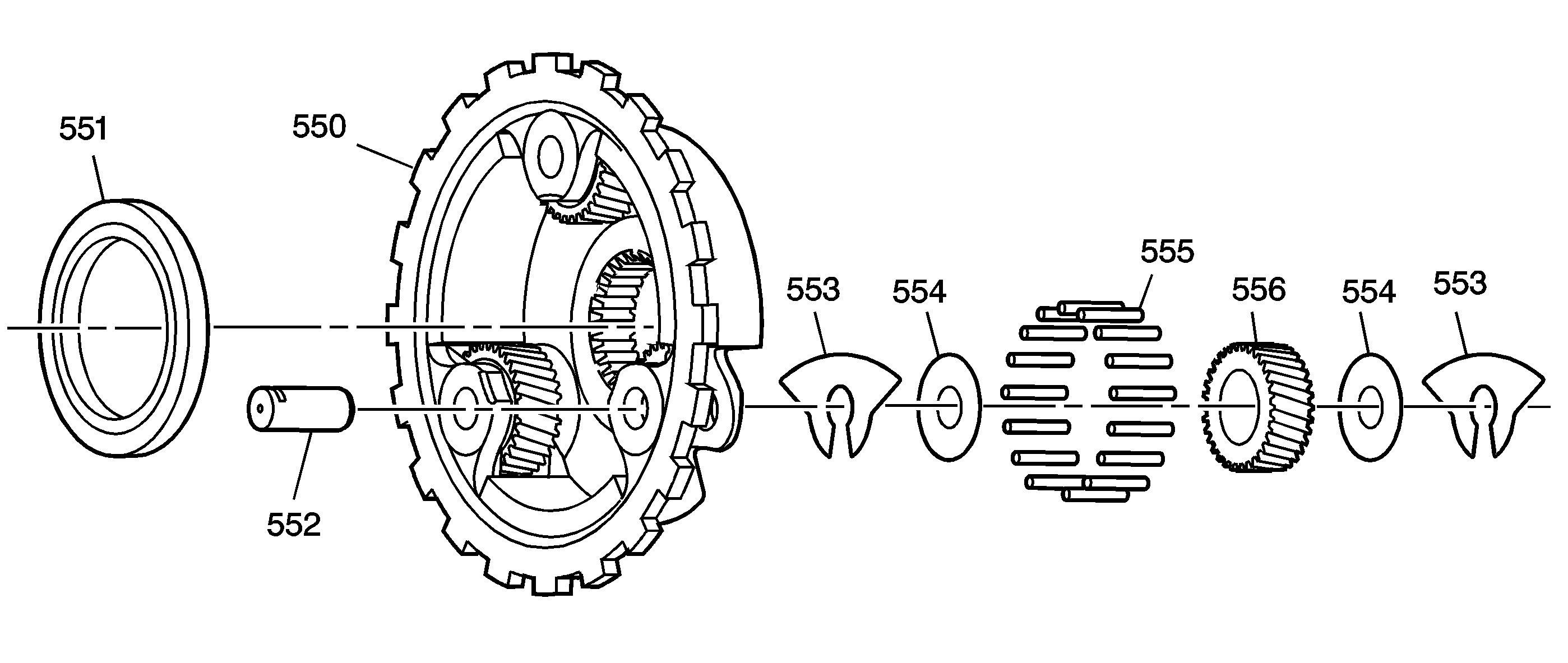
| Figure 6: |
Reaction Carrier Assembly
|
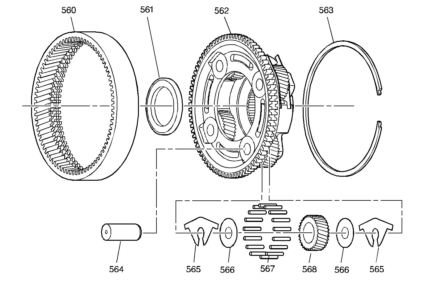
| Figure 7: |
Input Carrier Assembly
|
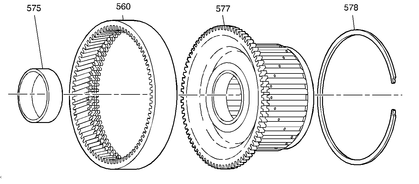
| Figure 8: |
Input Internal Gear and Forward Clutch Hub
|
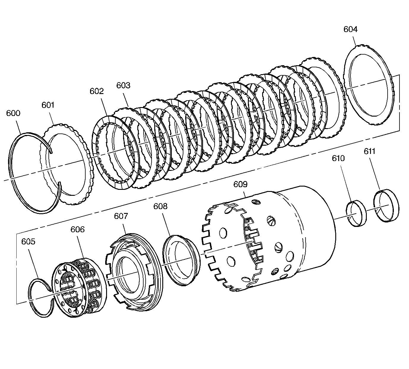
| Figure 9: |
Forward Clutch Assembly
|
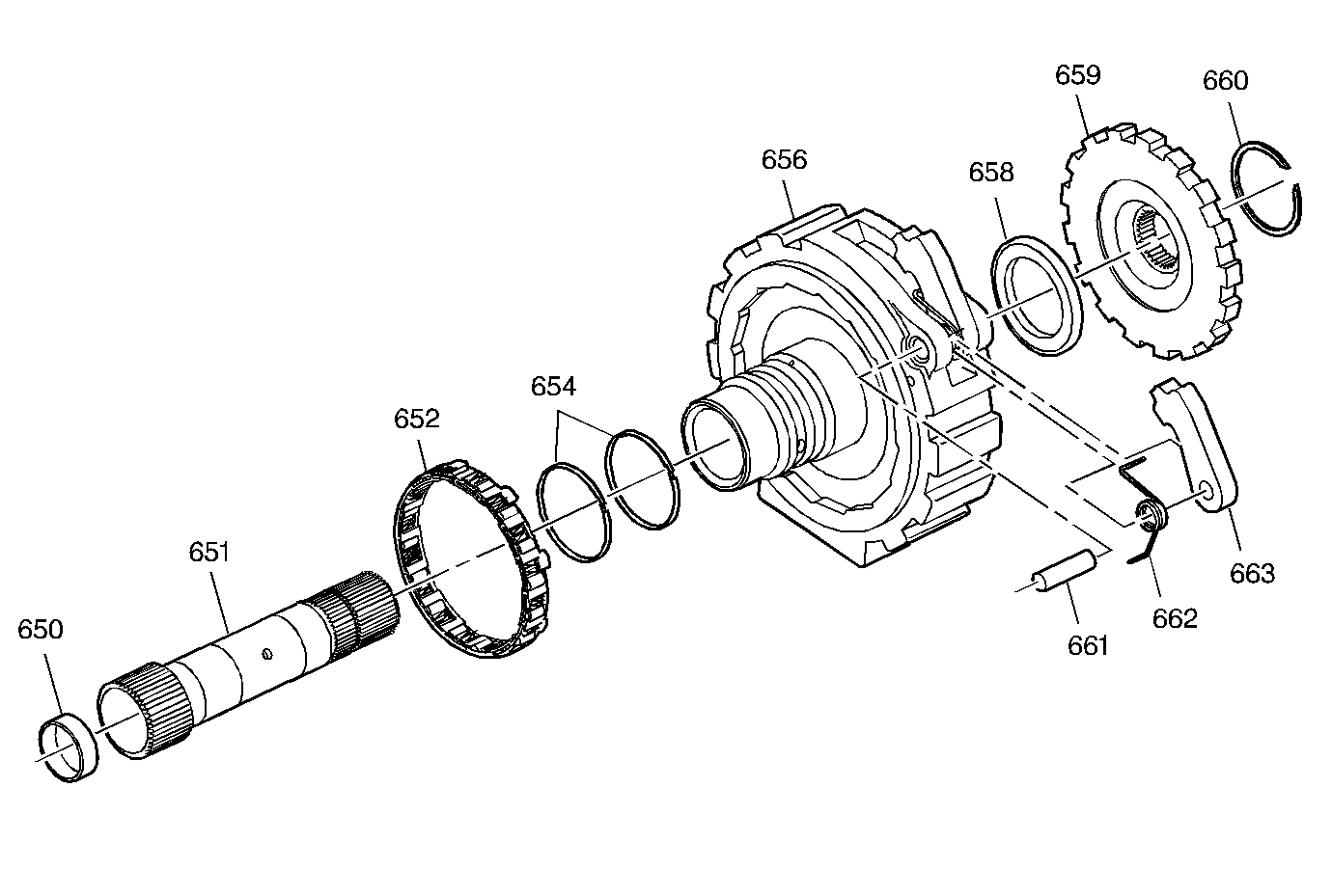
| Figure 10: |
Forward Clutch Support Assembly
|
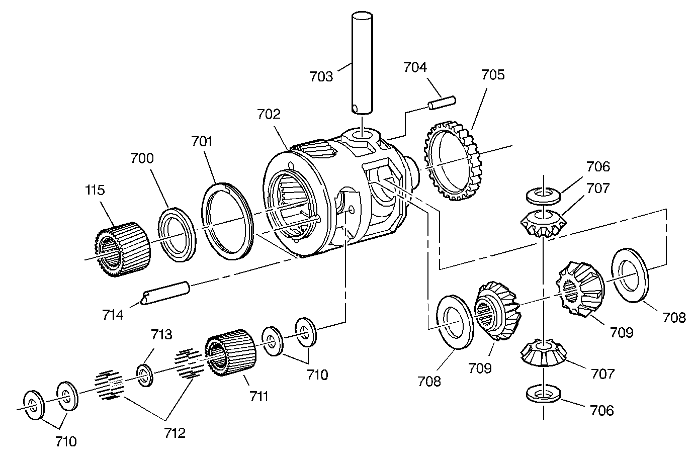
| Figure 11: |
Final Drive and Differential Assembly
|
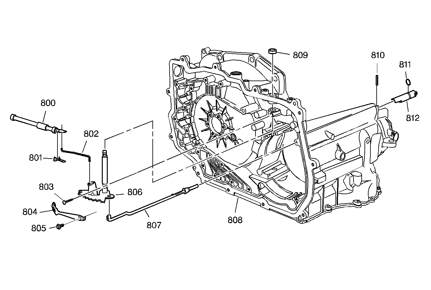
| Figure 12: |
Manual Shaft, Parking Panel and Actuator Assembly
|
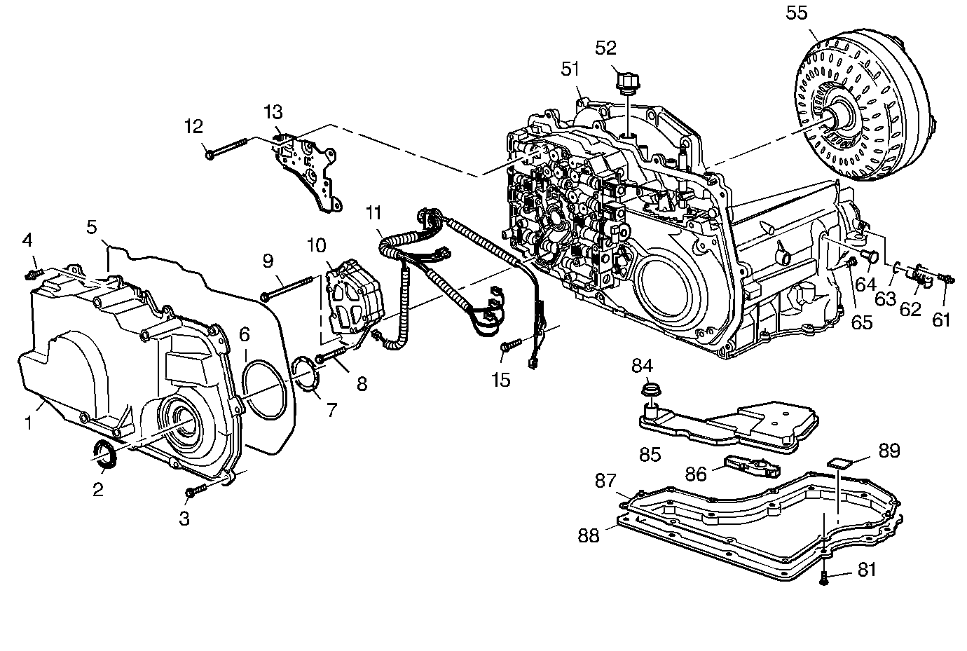
| Figure 13: |
Case & Associated Parts (1 of 3)
|
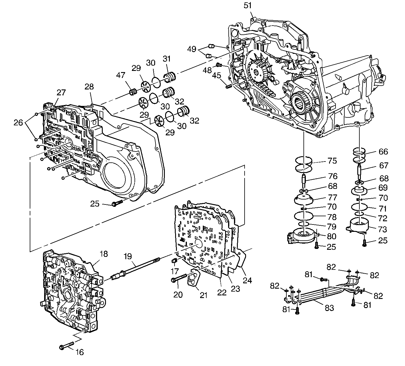
| Figure 14: |
Case & Associated Parts (2 of 3)
|
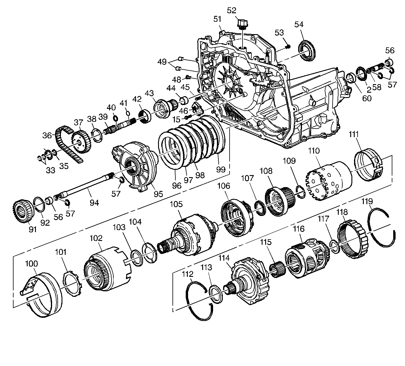
| Figure 15: |
Case and Associated Parts (3 of 3)
|
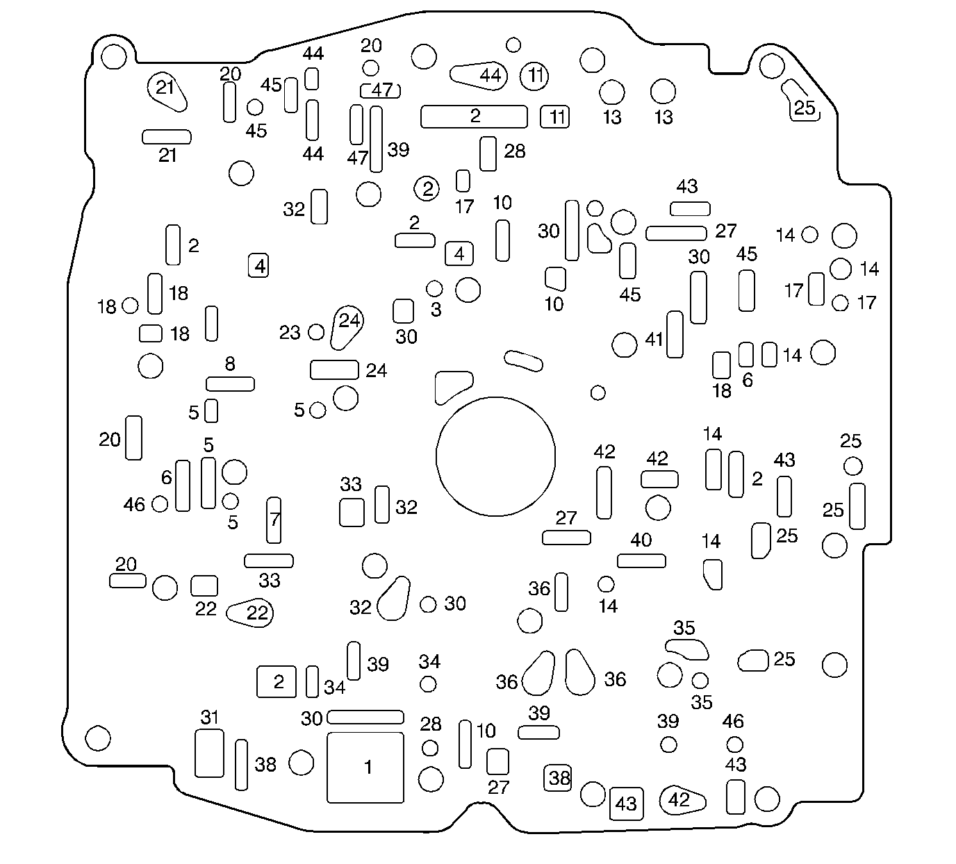
| Figure 16: |
Valve Body-to-Spacer Plate Gasket
|
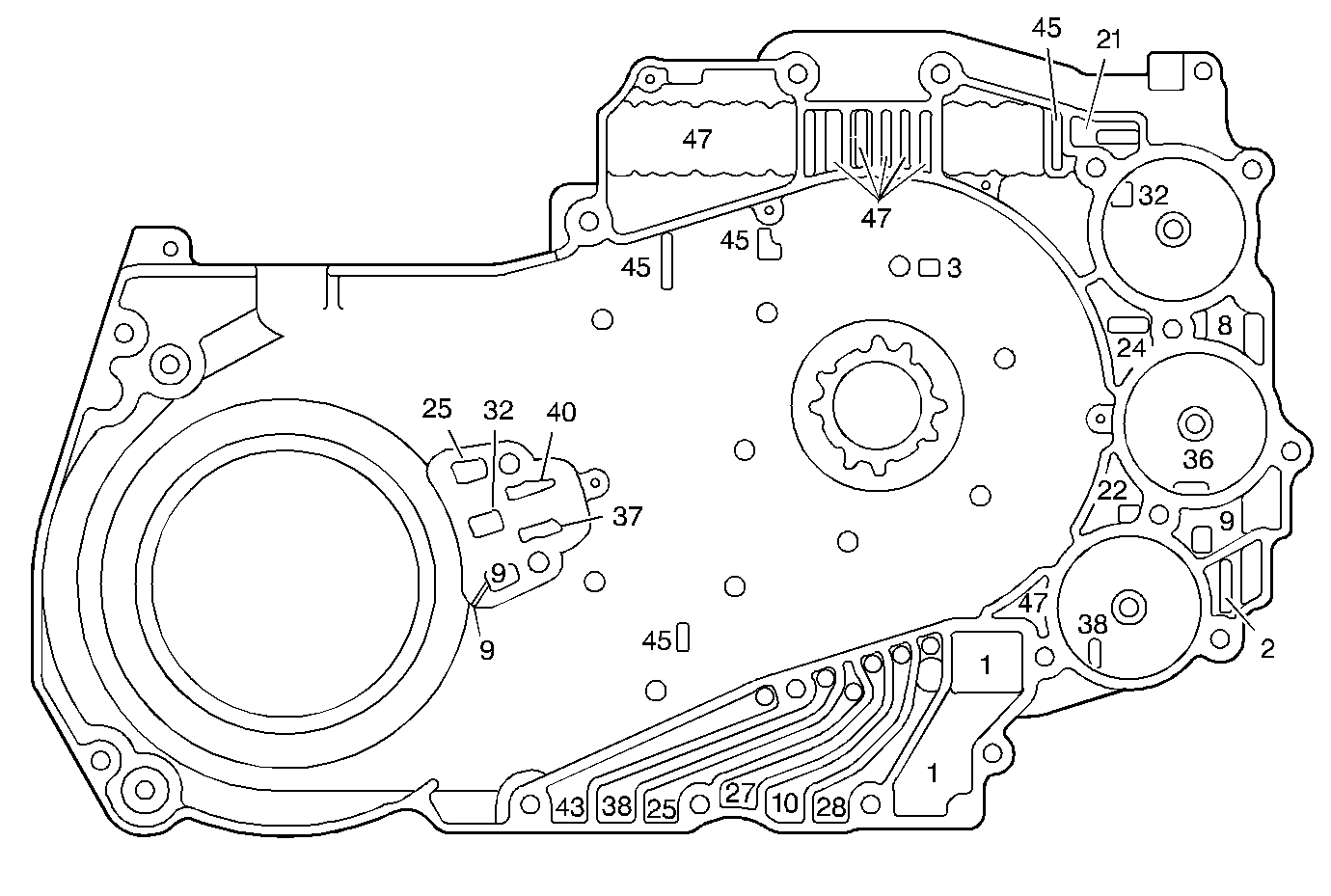
| Figure 17: |
Channel Plate Fluid Passages (Case Side)
|
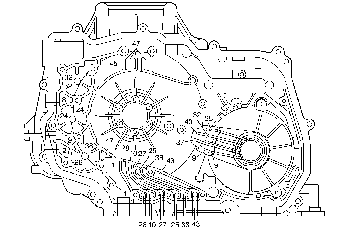
| Figure 18: |
Ease Passages - Channel Plate Side
|
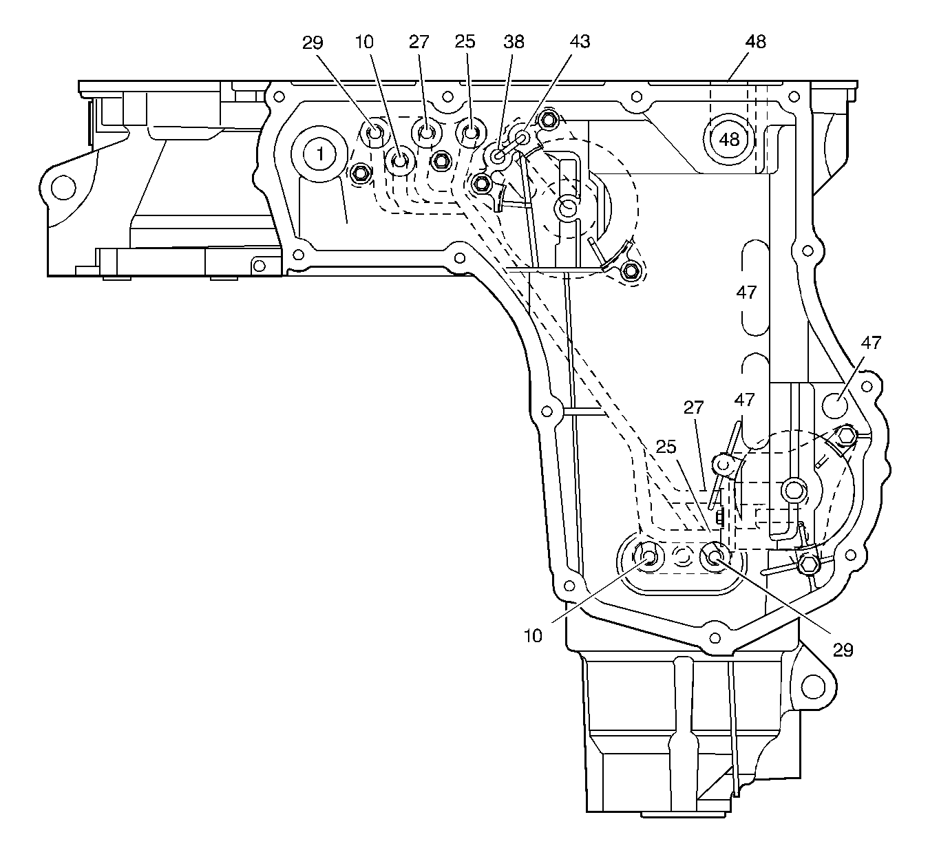
| Figure 19: |
Case Fluid Passages - Bottom
|
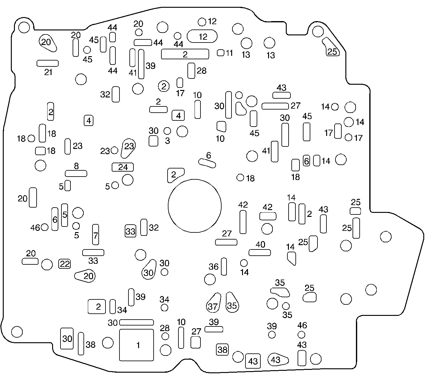
| Figure 20: |
Spacer Plate-to-Channel Plate Gasket
|
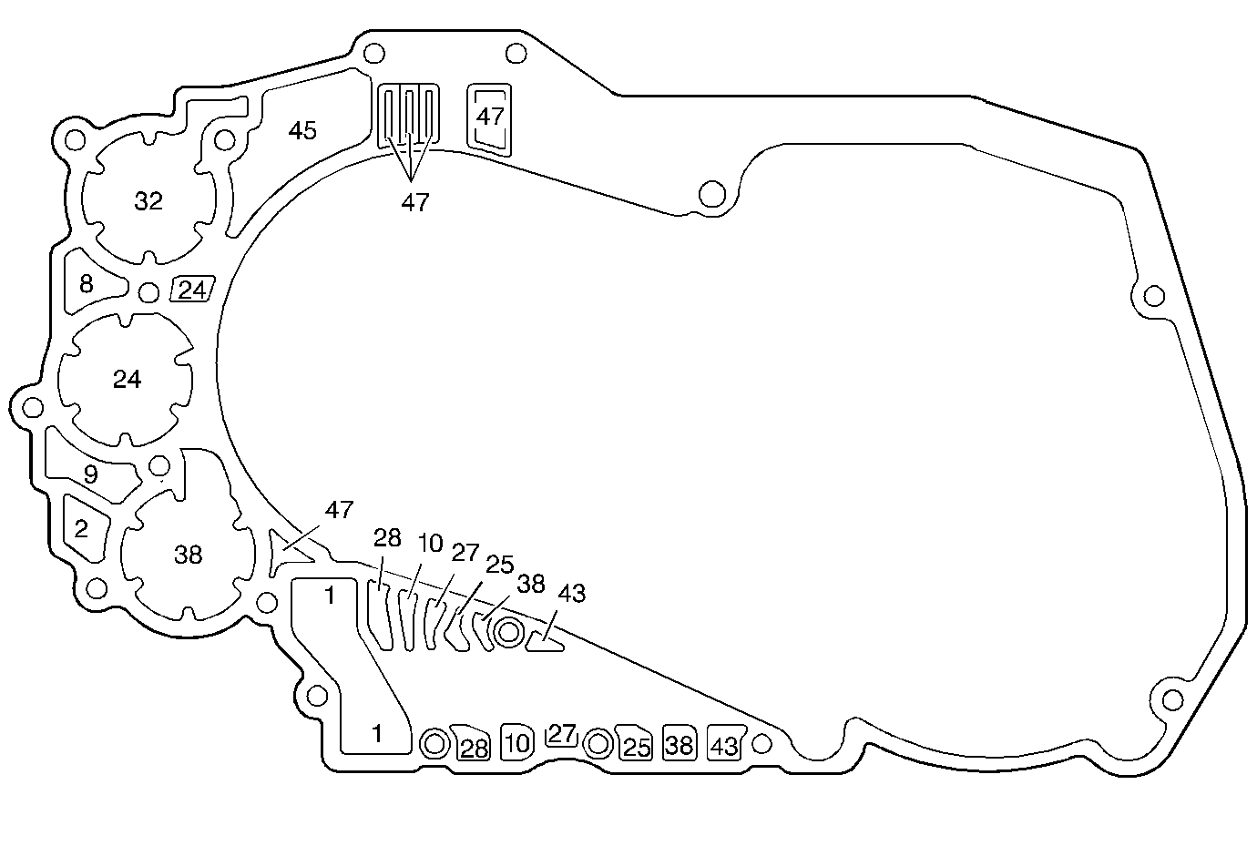
| Figure 21: |
Channel Plate to Case Gasket
|
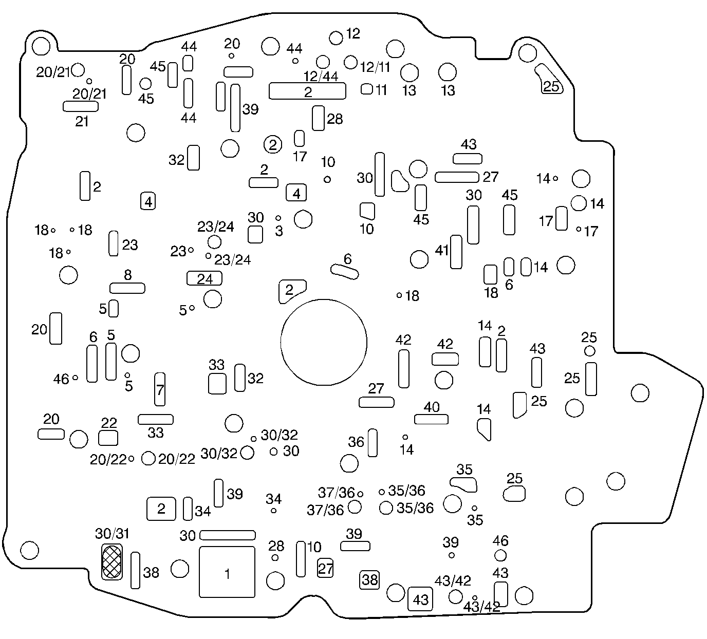
| Figure 22: |
Spacer Plate
|
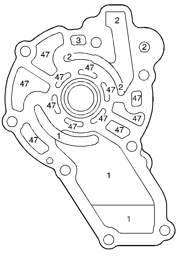
| Figure 23: |
Oil Pump Base Fluid Passages - Control Valve Body Side
|
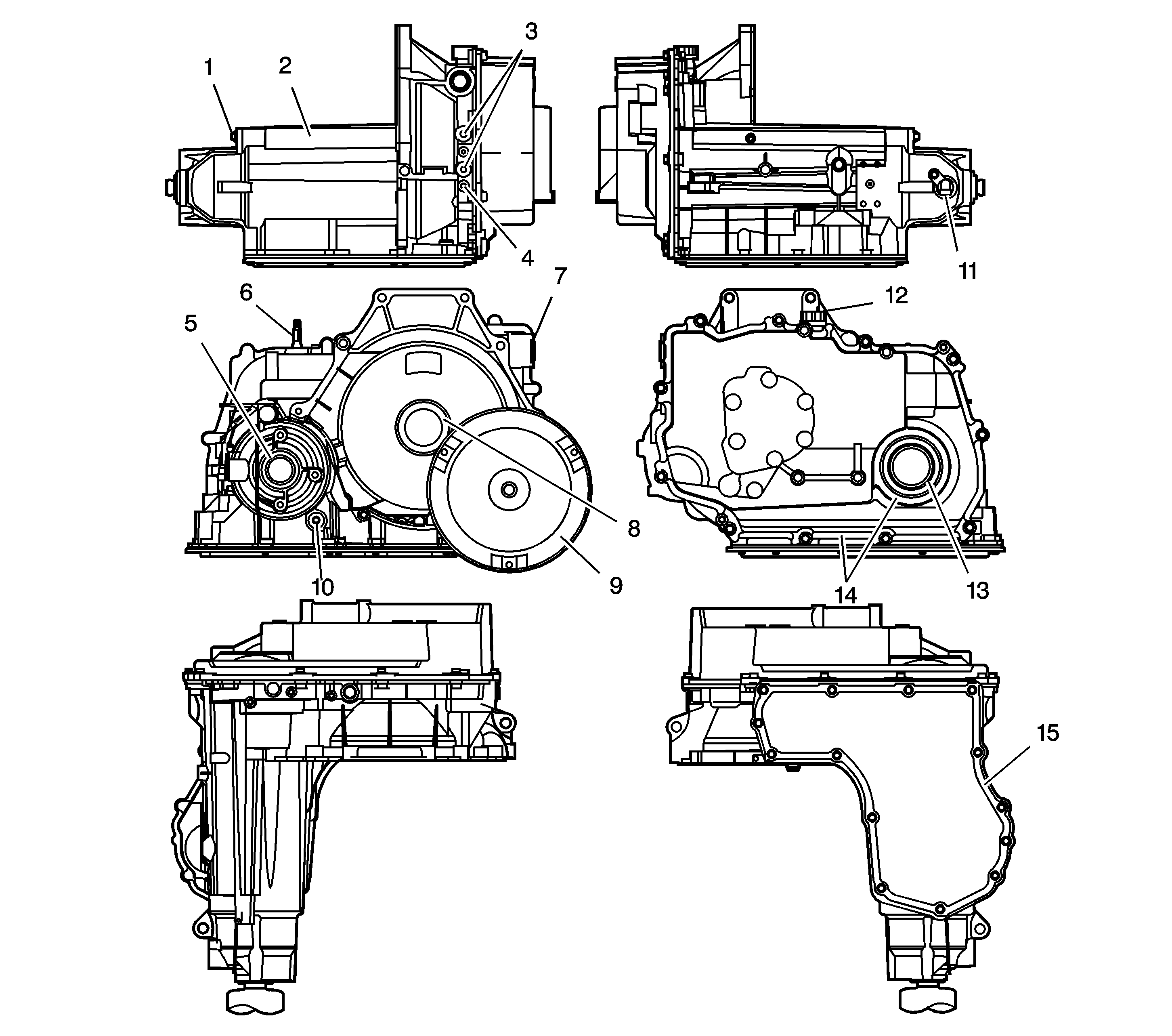
| Figure 24: |
Leak Inspection Points
|
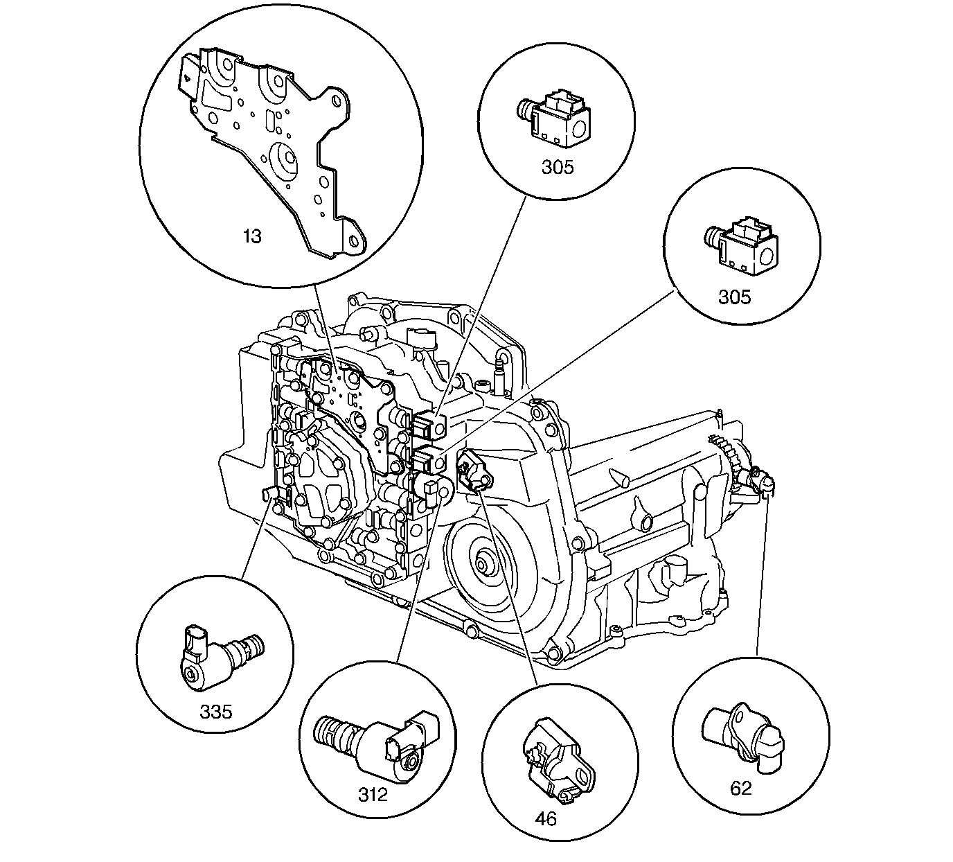
| Figure 25: |
Electronic Component Location Views
|
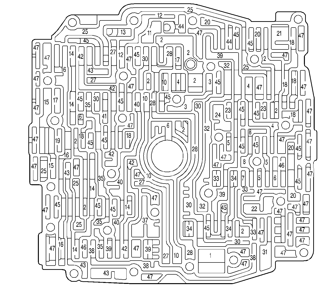
| Figure 26: |
Control Valve Body Fluid Passages (Channel Plate Side)
|
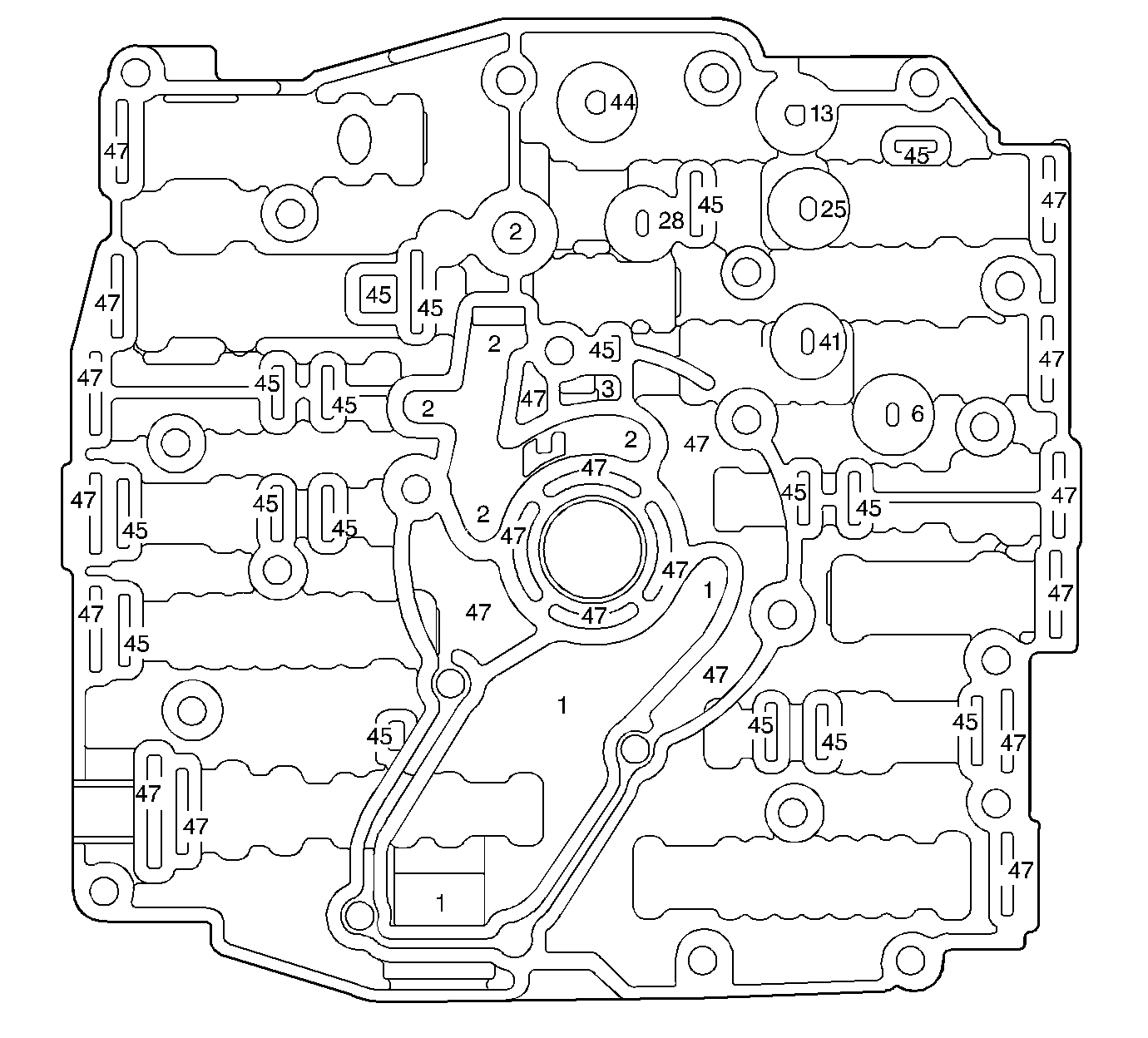
| Figure 27: |
Control Valve Body Fluid Passages (Oil Pump Base Side)
|
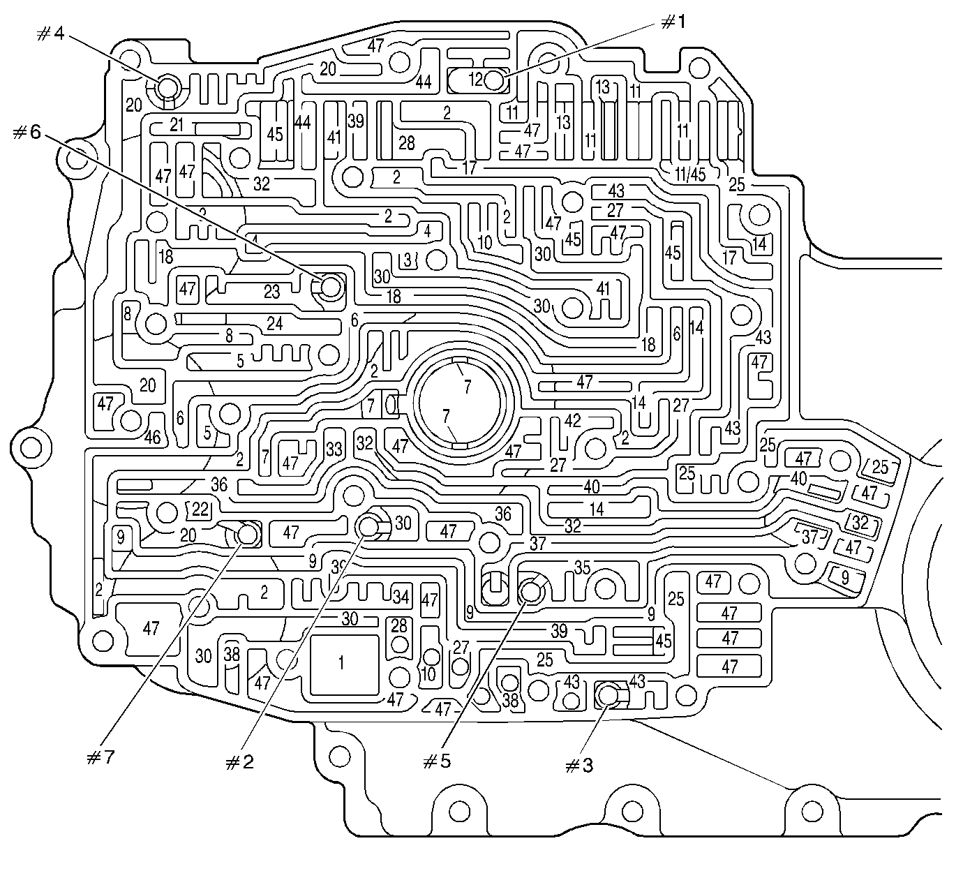
| Figure 28: |
Channel Plate Fluid Passages (Control Valve Body Side)
|