For 1990-2009 cars only
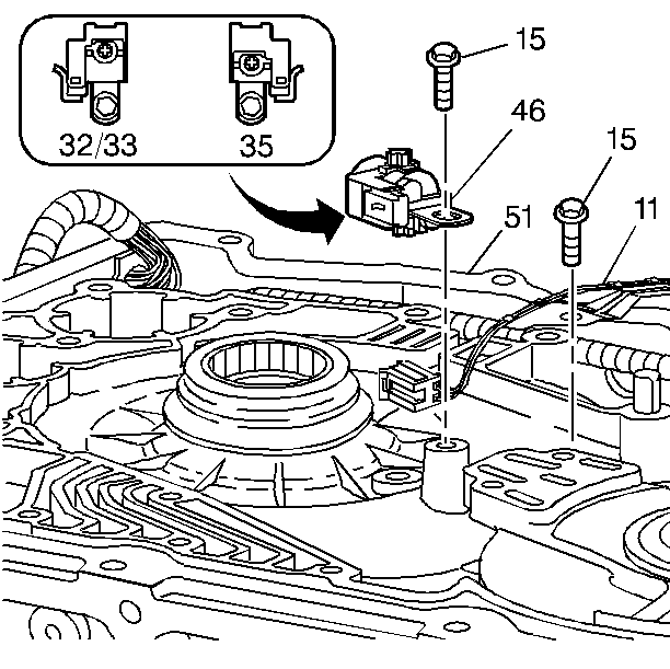
- Assemble the input speed sensor (46) to the transmission case (51).
- Install the input speed sensor bolt (15). Hand start and tighten the input speed sensor bolt to 12 N·m (9 lb ft).
- Route the input speed sensor wiring harness in the case channel.
- Connect the input speed sensor connector to the input speed sensor.
- Install the wire harness retainer and wire harness retainer bolt. Tighten the wire harness retainer bolt to 12 N·m (9 lb ft).

Important: The tab on the sensor housing (46) fits into the recess on the case boss. Orientation of the input speed sensor depends on the number teeth on the drive sprocket, which varies according to model application. For drive sprockets with 32 or 33 teeth, the speed sensor connector faces the bottom pan. For drive sprockets with 35 teeth, the speed sensor connector faces the fluid fill cap.
