CAMPAIGN: TRANSAXLE SHIFT IND. DISPLAY MAY NOT BE VISIBLE DUE

SUBJECT: TRANSAXLE SHIFT INDICATOR DISPLAY MAY NOT BE VISIBLE DUE TO INSTRUMENT CLUSTER TRIM PLATE SAG
U.S. Campaign Number Cross Reference: 95-C-64
Models: 1995 Pontiac Sunfire Models with Automatic Transaxle
TO: ALL GENERAL MOTORS DEALERS
General Motors of Canada Limited has determined that CERTAIN 1995 Pontiac Sunfire model vehicles may not conform to the Canada Motor Vehicle Safety Standard (CMVSS) 101, "Control Location and Identification." The instrument panel cluster trim plate/bezel on some of these vehicles may sag and cover the light emitting diode (LED) portion (lighted pointer above PRNDL) of the transaxle shift indicator display. If this occurs, the driver of the vehicle may not be able to determine, with certainty, the actual position of the transaxle gear selector. This could result in a driver inadvertently leaving the transaxle of a parked or idling vehicle in DRIVE, REVERSE, or NEUTRAL rather than PARK, or selecting an incorrect transaxle shift position while driving the vehicle. If either of these situations should occur, a vehicle crash could occur, and vehicle occupants and/or pedestrians could be injured.
To prevent this condition from occurring, dealers are to install a new instrument panel cluster trim plate/bezel assembly which is not subject to this condition.
VEHICLES INVOLVED:
Involved are CERTAIN 1995 Pontiac Sunfire model vehicles built within the following VIN breakpoints:
Year Model Plant Plant Code From Through ---- ----- ----- ---------- ---- ------- 1995 Pontiac Sunfire Lordstown 7 S7500075 S7532183 1995 Pontiac Sunfire Ramos Arizpe s SS800671 SS882368 1995 Pontiac Sunfire Genasys B SB200001 SB200203
NOTE: PLEASE CHECK DCS SCREEN 45 OR YOUR V.I.N. LISTING BEFORE PERFORMING CAMPAIGN TO ENSURE THAT THE VEHICLE IS AFFECTED. ONLY AFFECTED VIN'S WILL BE PAED.
All affected vehicles have been identified by the VIN listing provided to involved dealers with this bulletin. Any dealer not receiving a listing was not shipped any of the affected vehicles.
DEALER CAMPAIGN RESPONSIBILITY:
All unsold new vehicles in dealer's possession and subject to this campaign must be held and inspected/repaired per the Service Procedure of this Campaign Bulletin before owners take possession of these vehicles.
Dealers are to perform this campaign on all involved vehicles at no charge to owners, regardless of Kilometres traveled, age of vehicle, or ownership, from this time forward. Owners of vehicles recently sold from your new vehicle inventory with no owner information indicated on the dealer listing, are to be contacted by the dealer, and arrangements made to make the required correction according to instructions contained in this bulletin. This could be done by mailing to such owners a copy of the owner letter accompanying this bulletin. Campaign follow-up cards should not be used for this purpose, since the owner may not as yet have received the notification letter.
In summary, whenever a vehicle subject to this campaign is taken into your new or used vehicle inventory, or is in your dealership for service in the future, please take the steps necessary to be sure the campaign correction has been made before selling or releasing the vehicle.
CAMPAIGN PROCEDURES:
Refer to Section 4 of the Service Policies and Procedures Manual for the detailed procedure on handling Product Campaigns. Dealers are requested to complete the campaign on all transfers as soon as possible.
OWNER NOTIFICATION:
All owners of record at the time of campaign release are shown on the attached computer listing and have been notified by first class mail from General Motors (see copy of owner letter included with this bulletin). The listings provided are for campaign activity only and should not be used for any other purpose.
PARTS INFORMATION:
Parts required to complete this campaign should be ordered through regular channels, as follows:
Part Number Description Quantity/Vehicle ----------- ----------- ----------------- 22653357 Plate/Bezel, Trim-I/P Cluster-White 1 Also used for Red, Aqua & White interior 22653358 Plate/Bezel, Trim-I/P Cluster-Neutral 1
PARTS AND LABOR CLAIM INFORMATION:
Credit for the campaign work performed will be paid upon receipt of a properly completed campaign claim card or DCS Transmission in accordance with the following:
Repair Code Description Time Allowance ----------- ----------- --------------
2A Replace I/P Trim Plate/Bezel - Graphite, .7 Red, Aqua, White 3A Replace I/P Trim Plate/Bezel - Neutral .7
Time allowance includes 0. I hour for dealer administrative detail associated with this campaign. Parts credit will be based on dealer net plus 40% to cover parts handling.
SERVICE PROCEDURE:
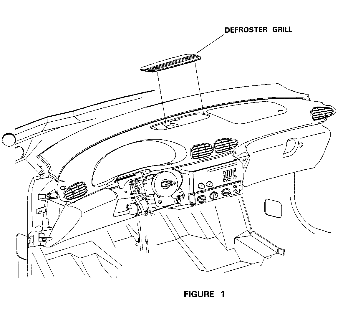
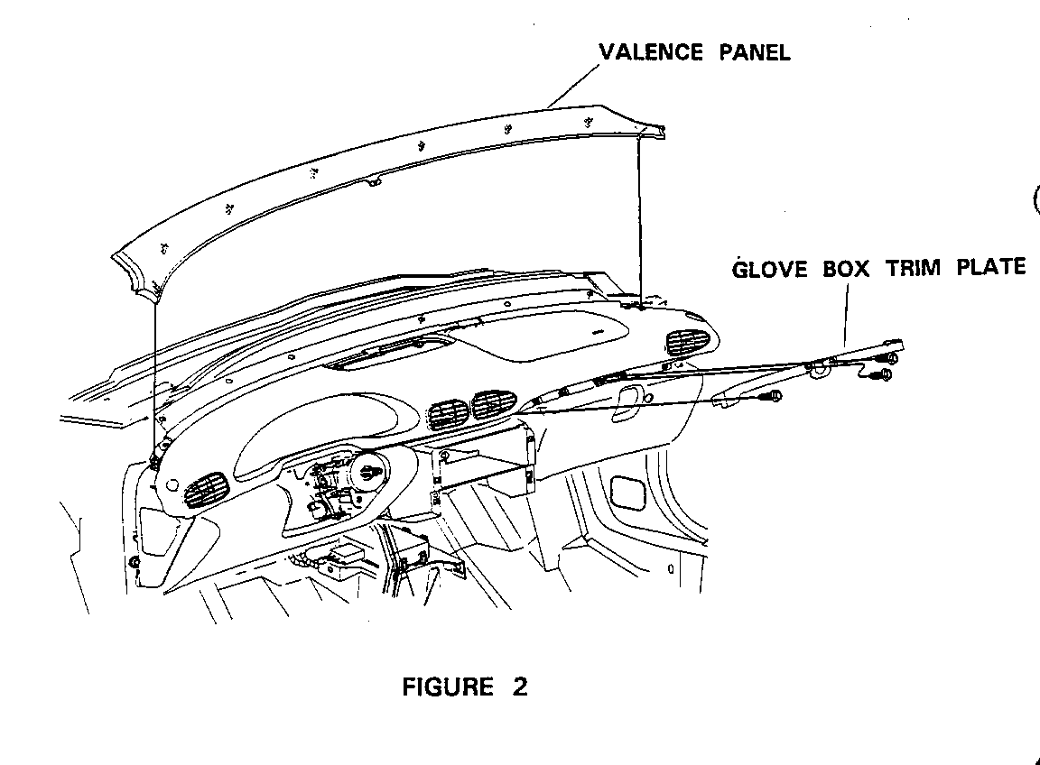
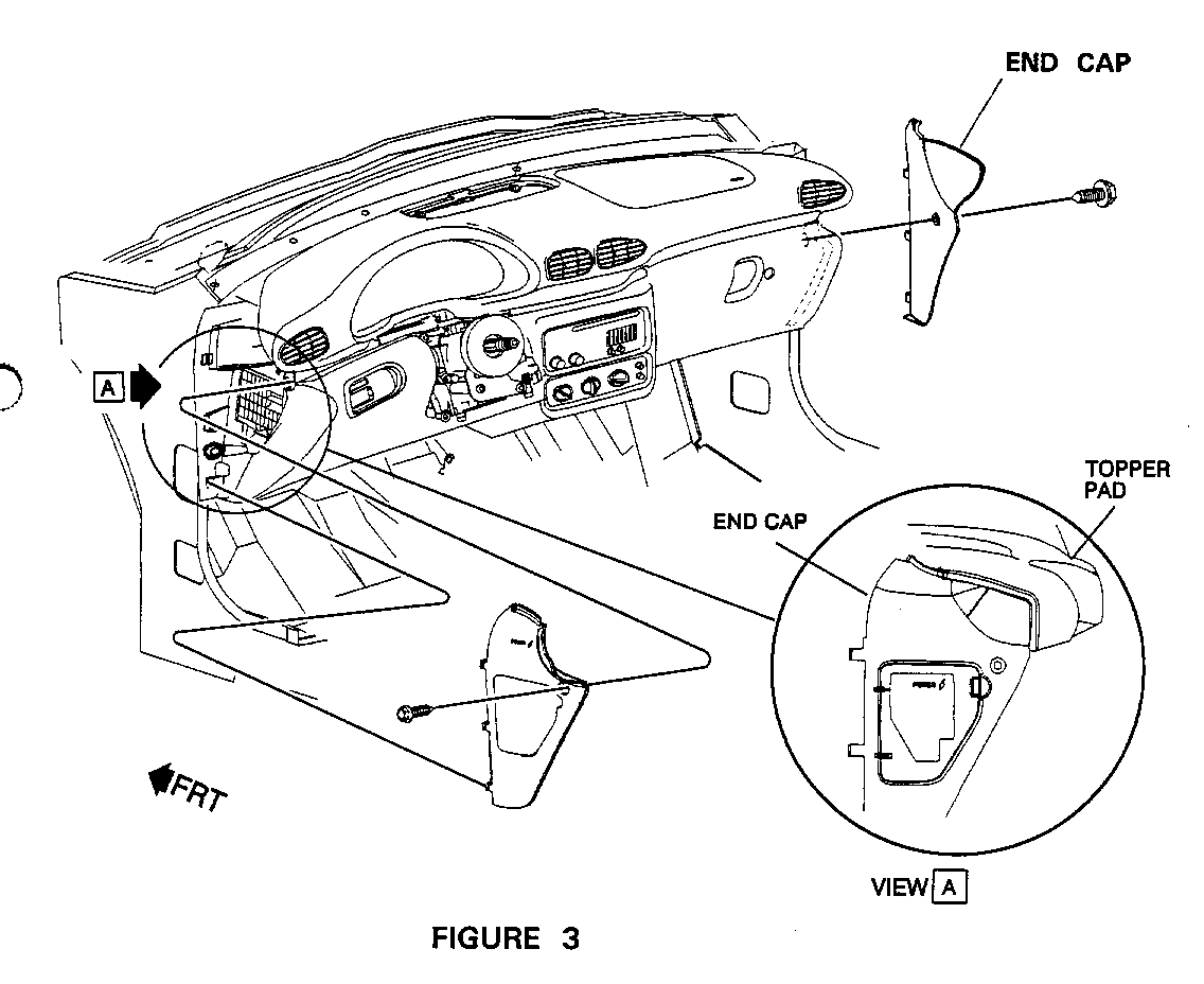
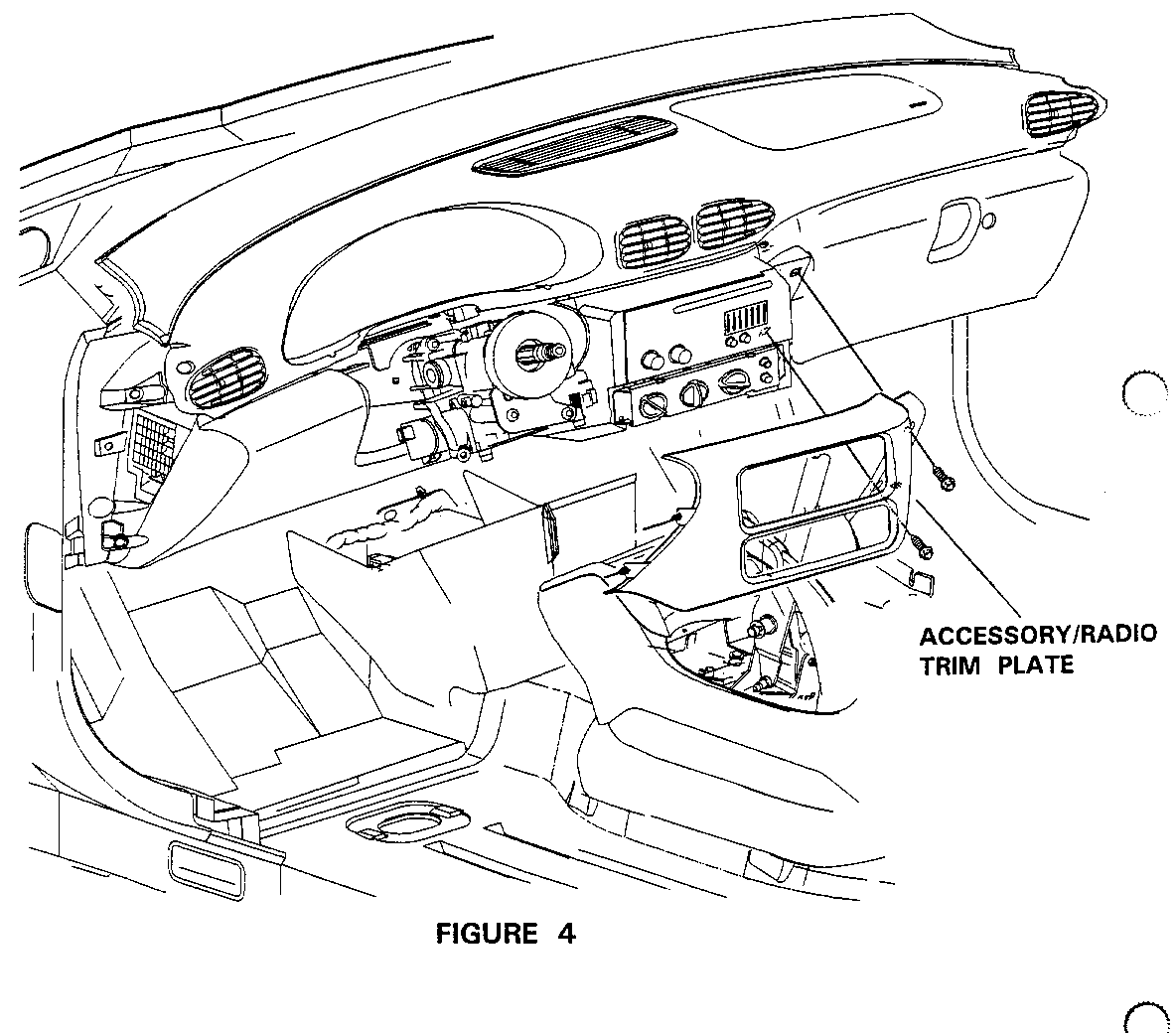
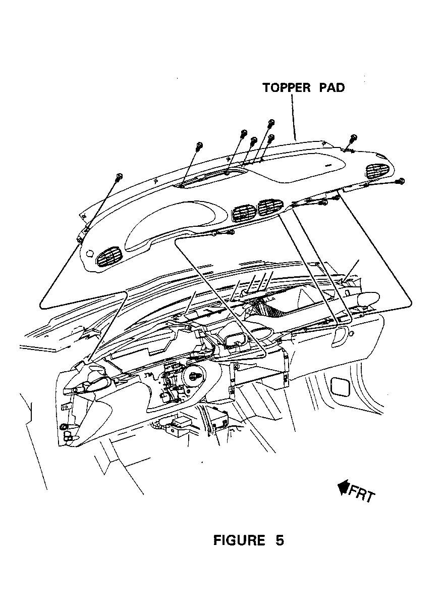
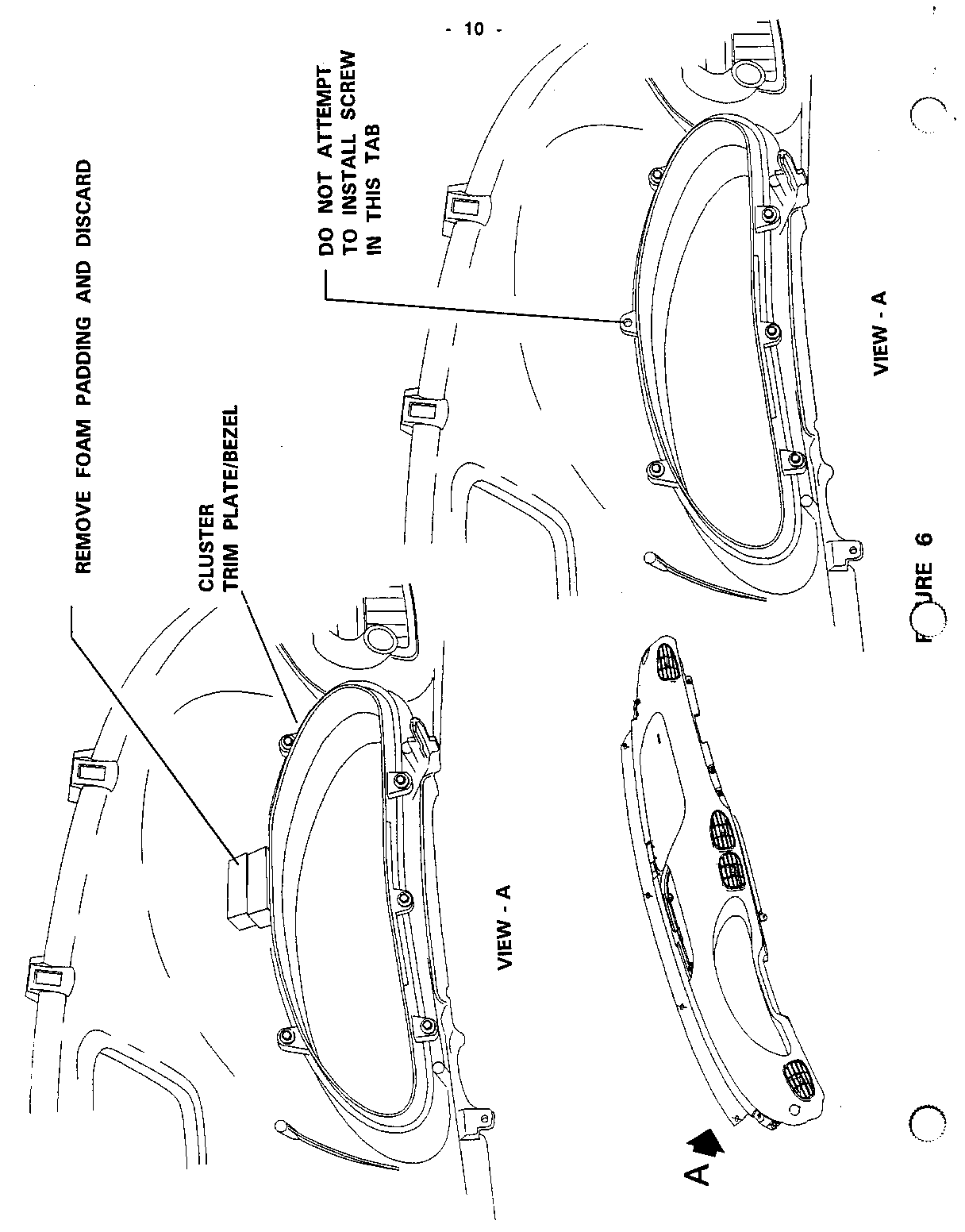
1. Disable Supplemental Inflatable Restraint (S.I.R.) system per instructions on Page 8C2-5 of the Service Manual. 2. Remove defroster grille from center of instrument pad (I/P) by carefully prying with a non-marring tool. See Figure 1. 3. Remove valence panel from front of I/P by carefully disengaging two pins from grommets (one at each end) and six clips. See Figure 2. IMPORTANT: DO NOT SCRATCH TOPPER PAD WITH VALENCE CLIPS WHEN REMOVING THE VALENCE. 4. Remove LH and RH end caps - one (1) Phillips head screw each end cap. See Figure 3. 5. Open glove box door to gain access to glove box trim plate screws and accessory trim plate screws. 6. Remove glove box trim plate - three (3) Phillips head screws. See Figure 2. 7. Remove two screws (7mm hex-head) from accessory/radio trim plate. Carefully remove trim plate, by rotating and pulling out. See Figure 4. 8. Remove topper pad as follows: 0 Two 7mm hex screws (gold/brass colored) forward of supplemental inflatable restraint (S.I.R.) panel. IMPORTANT: THE GOLD/BRASS COLORED SCREWS MUST BE REINSTALLED INTO THE SAME FASTENER LOCATIONS AT THE FRONT OF THE S.I.R. PANEL. 0 Four 7mm hex (or T15 torx) screws (black) from lower rear edge of pad. 0 Four 7mm hex (or T15 torx) screws (black) from upper forward edge of pad. Carefully remove topper pad by pulling away from I/P. IMPORTANT: HANDLE TOPPER PAD CAREFULLY TO AVOID DAMAGE. See Figure 5. 9. Remove thick gray foam padding (approx. I " thick) from area between underside of topper pad and topside of I/P cluster trim plate/bezel. 10. Remove I/P cluster trim plate/bezel from rear of topper pad - five 7mm hex (or T15 torx) screws. See Figure 6. 11. Install new I/P cluster trim plate/bezel to rear of topper pad with five 7mm hex (or T15 torx) screws, using the same fastener locations utilized on old trim plate/bezel. [Do not attempt to install a screw in the center upper screw position.] Tighten screws to 2.3 N.m (1.7 lbs. ft. or 20 lbs. in.). OR Screws are to be fully driven, seated, but not stripped. See Figure 6. IMPORTANT: MAKE SURE THAT FOM PADDING (GRAY - APPROX. 1" THICK) HAS BEEN REMOVED FROM UNDERSIDE OF TOPPER PAD ABOVE I/P CLUSTER TRIM PLATE/BEZEL. FAILURE TO REMOVE THIS PADDING MAY RESULT IN REPEATED SAGGING OF THE CLUSTER TRIM PLATE/BEZEL. 12. Carefully position topper pad to I/P. 13. Install four 7mm hex (or T15 torx) screws (black) to upper forward edge of topper pad. Tighten screws to 2.3 N.m (1.7 lbs. ft. or 20 lbs. in.). OR Screws are to be fully driven, seated, but not stdpped. See Figure 5. 14. Install four 7mm hex (or T15 torx) screws (black) to lower rear edge of topper pad. Tighten screws to 2.3 N.m (1.7 lbs. fL or 20 lbs. in.). OR Screws are to be fully driven, seated, but not stripped. See Figure 5. 15. Install two 7mm hex screws (gold/brass colored) to topper pad at forward edge of S.I.R. panel. Tighten screws to 2.3 N.m (1.7 lbs. ft. or 20 lbs. in.). OR Screws are to be fully driven, seated, but not stripped. See Figure 5. IMPORTANT: THE GOLD/BRASS COLORED SCREWS MUST BE REINSTALLED INTO THEIR ORIGINAL LOCATIONS AT THE FORWARD EDGE OF THE S.I.R. PANEL. SOME VEHICLES (A VERY SMALL NUMBER) MAY HAVE THREE FASTENER LOCATIONS AT THE FORWARD EDGE OF THE S.I.R. PANEL. ON THESE VEHICLES, THE FASTENERS MUST BE INSTALLED IN THE TWO LOCATIONS CLOSEST TO THE LEFT (DRIVER'S) SIDE OF THE S.I.R. PANEL. 16. Install glove box trim plate using three Phillips head screws. Tighten screws to 2.3 N.m (1.7 lbs. fL or 20 lbs. in.). OR Screws are to be fully driven, seated, but not stripped. See Figure 5. 17. Position RH and LH end caps to lower I/P and loose assemble screw to each end cap. Adjust end caps upward and rearward to minimize gap to topper pad before tightening screws. Tighten screws to 2.3 N.m (1.7 lbs. ft. or 20 lbs. in.).OR Screws are to be fully driven, seated, but not stripped. See Figure 3. 18. Position two pins on LH side of accessory trim plate into grommets in lower I/P and rotate trim plate into position. Install two Phillips head screws and tighten to 2.3 N.m (1.7 lbs. ft. or 20 lbs. in.). OR Screws are to be fully driven, seated, but not stripped. See Figure 4. 19. Close glove box door. 20. Carefully position valence to forward edge of topper pad. IMPORTANT: USE CAUTION WHEN POSITIONING VALENCE TO TOPPER PAD TO AVOID DAMAGE TO TOPPER PAD. 21. Position pins at each end of valence to I/P grommets and push in to seat. See Figure 2. 22. Secure, valence to topper pad by seating six clips. Seat outboard clips first and seat remaining clips by working inward towards middle panel. 23. Position defroster grille and push into topper pad until secure. See Figure 1. 24. Enable S.I.R. system per instructions on Page 8C2-6 of the Service Manual. 25. Install Campaign Identification label
INSTALLATION OF CAMPAIGN IDENTIFICATION LABEL
Clean surface of radiator upper mounting panel and apply a Campaign Identification Label. Make sure the correct campaign number is inserted on the label. This will indicate that the campaign has been completed.
VEHICLE RECALL NOTICE General Motors of Canada Limited 1908 Colonel Sam Drive Oshowa, Ontario L1H 8P7
February 1996
Dear General Motors Customer.
General Motors of Canada Limited has determined that CERTAIN 1995 Pontiac Sunfire model vehicles may not conform to the Canada Motor Vehicle Safety Standard (CMVSS) 101, "Control Location and Identification." The instrument panel cluster trim plate/bezel on some of these vehicles may sag and cover the light emitting diode (LED) portion (lighted pointer above PRNDL) of the transaxle shift indicator display. If this occurs, the driver of the vehicle may not be able to determine, with certainty, the actual position of the transaxle gear selector. This could result in a driver inadvertently leaving the transaxle of a parked or idling vehicle in DRIVE, REVERSE, or NEUTRAL rather than PARK, or selecting an incorrect transaxle shift position while driving the vehicle. If either of these situations should occur, a vehicle crash could occur, and vehicle occupants and/or pedestrians could be injured.
To prevent this condition from occurring, your dealer with install a new instrument panel cluster trim plate/bezel assembly which is not subject to this condition.
This service will be provided for you at no charge.
Please contact your GM dealer as soon as possible to arrange a service date.
If parts are required, ask your dealer for details regarding their availability. If parts are not in stock, they can be ordered before scheduling your service date.
This letter identifies your vehicle. Presentation of this letter to your dealer will assist their Service personnel in completing the necessary correction to your vehicle in the shortest possible time.
We are sorry to cause you this inconvenience; however, we have taken this action in the interest of your continued satisfaction with our products.
Customer Support Department General Motors of Canada Limited
5D31
General Motors bulletins are intended for use by professional technicians, not a "do-it-yourselfer". They are written to inform those technicians of conditions that may occur on some vehicles, or to provide information that could assist in the proper service of a vehicle. Properly trained technicians have the equipment, tools, safety instructions and know-how to do a job properly and safely. If a condition is described, do not assume that the bulletin applies to your vehicle, or that your vehicle will have that condition. See a General Motors dealer servicing your brand of General Motors vehicle for information on whether your vehicle may benefit from the information.
