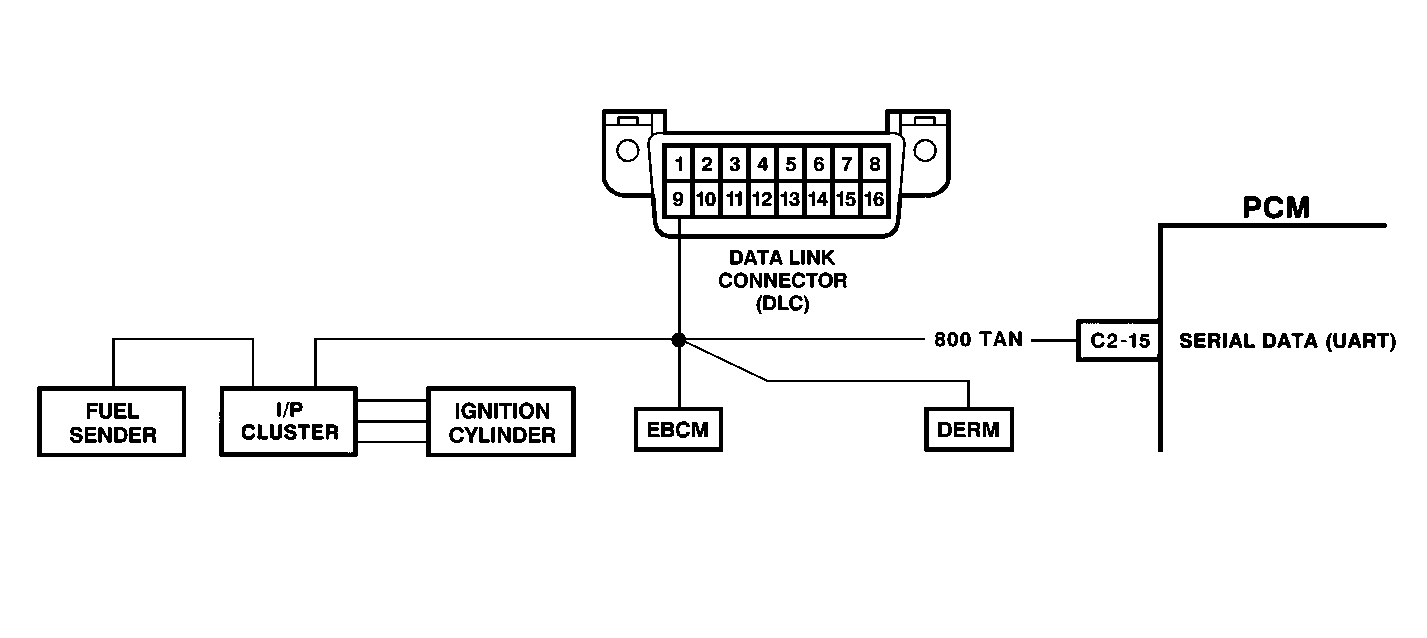
Circuit Description
UART serial data communication is a method by which components or modules can transfer information to each other. The serial data communication circuit is connected to four components or modules: the Powertrain Control Module (PCM), Diagnostic Energy Reserve Module (DERM), Electronic Brake Control Module (EBCM), and the electronic Instrument Panel Cluster (IPC). The IPC is the master of this network and sends out updated information and requests updated information from the other modules through the serial data circuit. Each module in turn responds back to the IPC with updated information used by the IPC. The PCM communicates with the EBCM through the IPC over the serial data circuit. If any of the modules cannot respond to each other; a DTC is set in each applicable module.
Conditions for Setting the DTC
| • | PCM does not receive 25 valid responses from the IPC. |
| • | System voltage is greater than 6.8 volts. |
| • | Above conditions are met for 10 seconds. |
Action Taken When the DTC Sets
| • | The PCM will record operating conditions at the time the diagnostic fails. This information will be stored in the Failure Records buffer. |
| • | A history DTC is stored. |
| • | IPC illuminates the telltales the PCM controls through the serial data line: |
| - | Low coolant |
| - | low oil level |
| - | Volts |
Conditions for Clearing the MIL/DTC
| • | A history DTC will clear after 40 consecutive warm up cycles without a fault. |
| • | A scan tool can clear the MIL/DTCs. |
Diagnostic Aids
| • | Move the PCM and IPC connectors while watching the IPC to see if serial data is lost. When serial data is lost, the IPC telltales are illuminated. This is a good indication that serial data is lost to the IPC. |
| • | An intermittent problem may be caused by electrical interference on the ground circuit of the IPC, a poor connection, rubbed through wire insulation, or a wire that is broken inside the insulation. |
| • | Any circuitry, that is suspected as causing the intermittent complaint, should be thoroughly checked for the following conditions: |
| - | Backed out terminals |
| - | Improper mating |
| - | Broken locks |
| - | Improperly formed |
| - | Damaged terminals |
| - | Poor terminal to wire connection |
| • | Install an additional ground wire from the IPC to the negative side of the battery if electrical interference is suspected. |
Test Description
Number(s) below refer to the step number(s) on the Diagnostic Table.
-
The Powertrain OBD System Check prompts the technician to complete some basic checks and store the freeze frame and failure records data on the scan tool if applicable. This creates an electronic copy of the data taken when the fault occurred. The information is then stored on the scan tool for later reference.
-
When all PCM controlled telltales are illuminated, serial data is lost to the IPC.
-
If the scan tool cannot read serial data from the IPC, be sure that the scan tool is working properly on another vehicle.
-
The open in the circuit can be narrowed down by determining which modules can communicate with the scan tool.
-
A short in the UART serial data circuit will cause all of the IPC telltales in step 2 to illuminate plus the additional telltales controlled by the other modules on the circuit.
-
If the scan tool can communicate normally with the IPC once the PCM connectors are disconnected, then the PCM is causing the short on the UART serial data circuit.
-
Replacement PCM's must be reprogrammed. Refer to the latest Techline information for programming procedures.
-
If no faults have been found at this point and no additional DTC's were set, refer to Diagnostic Aids for additional checks and information.
Step | Action | Value(s) | Yes | No | ||||||||
|---|---|---|---|---|---|---|---|---|---|---|---|---|
Was the Powertrain On-Board Diagnostic (OBD) System Check performed? | -- | Go to | ||||||||||
Are all the telltales ON and the gauges not operating properly? | -- | |||||||||||
Install a scan tool. Can the scan tool communicate with IPC? | -- | |||||||||||
Check the UART serial data circuit for an open and repair as necessary. Was a repair necessary? | -- | |||||||||||
Check the UART serial data circuit for a short to ground or to voltage and repair as necessary. Was a repair necessary? | -- | |||||||||||
6 | Check the PCM connector for a poor connection and repair as necessary. Was a repair necessary? | -- | ||||||||||
Can the scan tool communicate with the IPC? | -- | Go to Section 8A-50 | ||||||||||
Replace the PCM. Is the action complete? | -- | -- | ||||||||||
9 |
Does the scan tool indicate that this diagnostic has ran and passed? | -- | ||||||||||
Check if any additional DTC's are set. Are any DTC's displayed that have not been diagnosed? | -- | Go to applicable DTC table | System OK Refer to Diagnostic Aids |
