Removal Procedure
Tools Required
- Disconnect the negative battery cable. Refer to
Caution: Unless directed otherwise, the ignition and start switch must be in the OFF or LOCK position, and all electrical loads must be OFF before servicing
any electrical component. Disconnect the negative battery cable to prevent an electrical spark should a tool or equipment come in contact with an exposed electrical terminal. Failure to follow these precautions may result in personal injury and/or damage to
the vehicle or its components.
in General Information.
- Remove the oil pan. Refer to
Oil Pan Replacement
.
- Remove the balance shafts. Refer to
Balance Shaft Housing Replacement
.
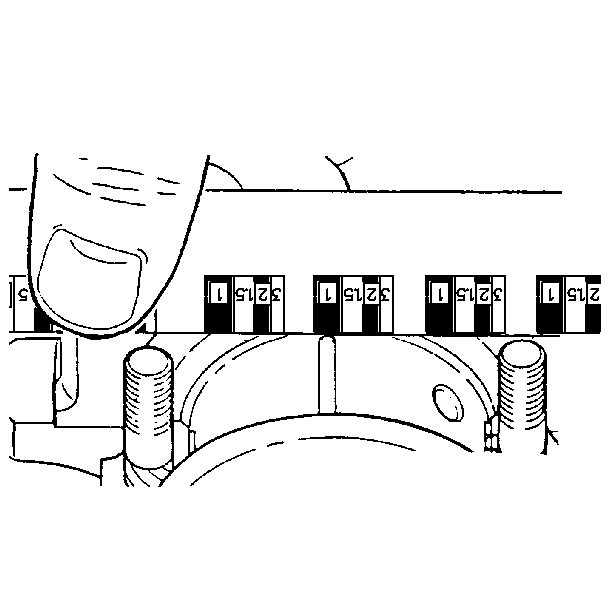
- Remove the rod bearing cap.
- Remove the main bearing cap.
- Inspect the bearing surfaces for wear and gouges or imbedded foreign
material.
Important: Bearing failure, other than normal wear must be investigated carefully.
Inspect the crankshaft or connecting rod and the bearing bores.
- Inspect outer surfaces for the following things:
| • | Wear. Surface wear indicates either movement of the insert or
high spots in the surrounding material. |
- Inspect the thrust surfaces for the following things:
Important: Method A yields measurements from which the bearing clearance can be
computed. Method B yields the bearing clearance directly. Method B does not
give any indication of bearing journal runout.
Do not mix the inserts of different nominal size.
| • | Grooving. Grooves are caused by irregularities of the crankshaft
thrust surface. |
- Remove the bearing cap bolts. If the bolts are stretched replace
them.
- Measure the bearing clearance. To determine the correct replacement
insert size, the bearing clearance must be measured accurately. Either of
the following two methods may be used, however, method A gives more reliable
results and is preferred.
Method A
- Measure the crankshaft journal diameter with a micrometer in several
places, approximately 90 degrees apart, and average the measurements.
- Measure the taper and runout
- Measure the bearing insert I.D. with an inside micrometer. Measure
at 90 degrees to the split line of the bearing.
Method B
- Clean and install the bearing inserts, and the crankshaft into
the block.
- Place a piece of gaging plastic across the entire bearing width.
- If the main bearing clearance is being measured, support the crankshaft
away from the gaging plastic so total clearance is being measured.
- Seat the bearing cap carefully by tapping it lightly with a suitable
tool.
Notice: To prevent the possibility of cylinder block and/or main bearing cap
damage, tap the main bearing caps into the cylinder block cavity with a brass
or leather mallet before installing the attaching bolts. Do not use the attaching
bolts to pull the caps into their seats.
- Tighten the bearing cap bolts to specification.
Important: Do not rotate the crankshaft.
- Remove the bearing cap, leaving the gaging plastic in place. It
does not matter whether the gaging plastic adheres to the journal or to the
bearing cap.
- Measure the flattened gaging plastic package.
- Remove all traces of the gaging plastic after measuring.
Installation Procedure
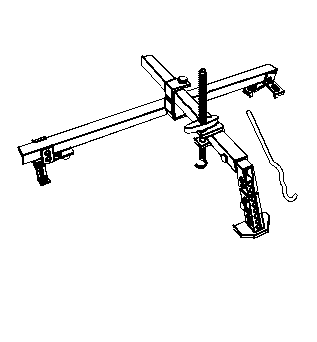
Important: If the number one piston and the rod assembly were removed, the engine
must be lifted prior to reinstallation in order to gain clearance for the
torque angle meter usage. The engine does not have to be lifted to reinstall
numbers two, three, and four piston and rod assemblies. Use the engine support
fixture to gain this clearance.
- Install the balance shafts. Refer to
Balance Shaft Housing Replacement
.
- Install the new oil pan gasket. Refer to
Oil Pan Replacement
.
- Install the oil pan. Refer to
Oil Pan Replacement
.
- Start the engine and inspect for leaks. Refer to Oil Consumption Diagnosis
.
- Connect the negative battery cable.
