Caution: Bodily injury may occur if carburetor cleaning fluid is exposed to the
skin or if the fumes are inhaled.
Cleaning Procedure

Important: It is essential that the piston ring grooves are cleaned of carbon to
the bare metal. Do not scrape the piston skirt.
- Clean the following contaminates from the piston, the piston pin and
connecting rod:
- Clean the varnish from the piston pin by soaking it in Parts Immersion
Solvent GM P/N 12345368 or equivalent.
Connecting Rod Inspection Procedure
- Inspect the connecting rod for bending or twisting.
- Install the connecting rod cap. Place the connecting rod assembly
on a checking fixture and check if it is bent or twisted.
- Replace the connecting rod if it is bent or twisted. Do not attempt
to straighten it. Check the new connecting rods before using them.
- Inspect the outside of the connecting rod bearing and the I.D.
of the connecting rod lower end for wear, indicating high spots in the connecting
rod lower end.
- Inspect the connecting rod bolts for stretching by comparing them
with a new bolt.
- Inspect the upper end for scoring.
Piston and Piston Pin Inspection Procedure
- Inspect the piston pin for the following conditions:
| • | Galling caused by improper installation |
| • | The fit in connecting rod and piston |
- Inspect the piston for the following conditions:
| • | Broken ring groove lands |
Piston Rings Measuring Procedure
- Select a set of new piston rings, if necessary.

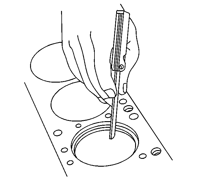
- Use the following procedure to measure the piston ring end gap:
| 2.1. | Place the piston into the cylinders at the bottom of the ring
travel. |
| 2.2. | Place a piston ring on top of the piston. |
| 2.3. | Back off the piston. |
| 2.4. | Measure the ring gap. If the gap is below specification increase
the gap by carefully filing off excess material. |
Important: High spots in the ring groove may be cleaned up by careful use of a
point file. Do not attempt to cut the ring groove.

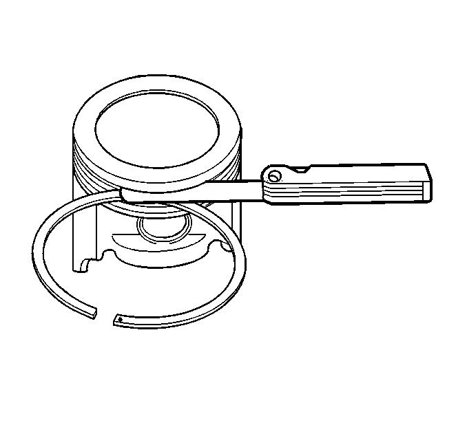
- Measure the piston compression ring side clearance. Roll the piston
ring around the groove in which it will be installed and measure the side
clearance. If the ring is too thick, try another ring.
Connecting Rod and Piston Assembly Procedure

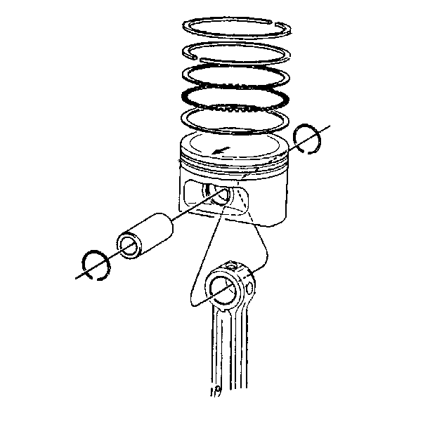
- The piston ring must be installed on the connecting rod so that the
mark on the piston faces toward the front of the engine and the oil squirt
hole faces the left (exhaust) side of the engine.
- Coat the piston pin with clean engine oil.
- Assemble the piston pin into the piston and the connecting rod.
- Install the retainers.
- Inspect the piston for freedom of movement.
Notice: Use a piston ring expander to install the piston rings. The rings may
be damaged if expanded more than necessary.
- Assemble the following oil control ring assembly components:
| • | The lower oil control ring |
| • | The upper oil control ring |
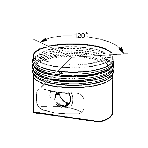
Important: In order to provide and effective compression seal, the ring gaps must
be staggered.

- Assemble the lower and upper compression rings with the identification
mark facing up. The top compression ring is made from ductile iron with a
molybdenum facing and phosphate coated sides. The second compression ring
is grey iron. A mark is machined into the top of the second compression ring.


