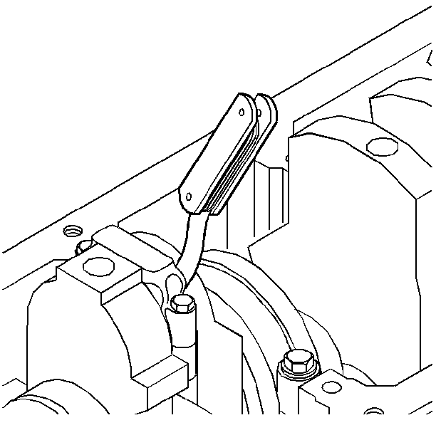
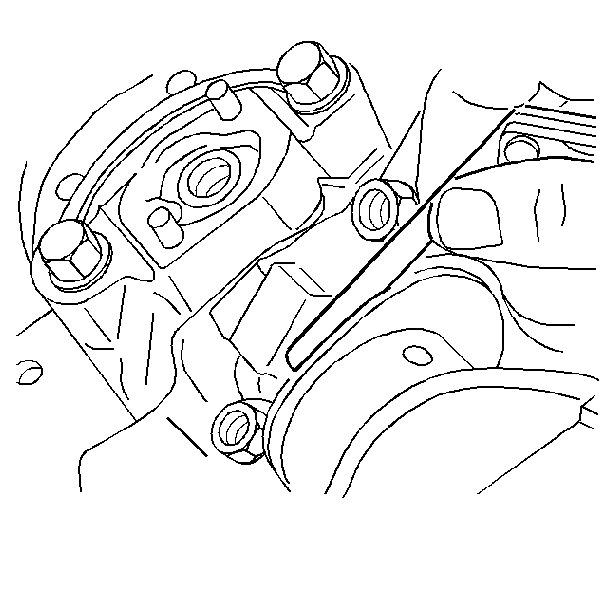
Inspection Procedure
- Inspect the bearing surfaces for the following conditions:
- If foreign material exists, determine its cause and repair it.
- Inspect the oil pan for sludge and residue.
- Inspect the outer surfaces for the following conditions:
- Inspect the main thrust bearing and thrust surfaces for the following conditions:
- Investigate bearing failure, other than normal wear.
- Inspect the crankshaft or connecting rod and the bearing bores.
- Inspect the bearing cap bolts. Replace any bolts that are stretched.
| • | Wear |
| • | Gouges |
| • | Imbedded foreign material |
| • | Surface or spot wear indicating movement of the insert or high spots in the surrounding material |
| • | Overheating or discoloration |
| • | Looseness or rotation, indicating flattened tangs and worn grooves |
| • | Wear |
| • | Grooves |
Important: Measure the bearing clearance correctly in order to determine the correct replacement insert size. Use either method A or method B. Method A gives more reliable results and is preferred. Method A yields measurements from which the bearing clearance can be computed. Method B yields the bearing clearance directly. Method B does not indicate bearing or journal runout. Do not mix inserts of different nominal size.
Method A
- Use a micrometer in order to measure the crankshaft journal diameter in several places approximately 90° apart. Average the measurements.
- Compute the taper and runout to ensure they are within the specification limits.
- Use an inside micrometer in order to measure the bearing insert ID. If you are replacing the inserts, measure using the new inserts.
- Install the bearing inserts in the correct cylinder block bore or connecting rod bore. Tighten the rod and the main bearing cap bolts or nuts to the correct specifications.
- Measure the inside diameter with an inside micrometer. Measure using the new inserts, if the current inserts are being replaced.
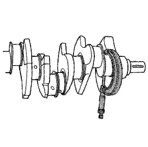
Method B
- Clean and install the bearing inserts.
- Install the crankshaft into the cylinder block.
- Place a piece of gaging plastic across the entire bearing width.
- If the main bearing clearance is being measured, support the crankshaft away from the gauging plastic in order for total clearance to be measured.
- Seat the bearing cap carefully by tapping it lightly with a suitable tool.
- Tighten the bearing cap bolts to specifications.
- Remove the bearing cap. Leave the gauging plastic in place. It does not matter whether the gaging plastic adheres to the journal or to the bearing cap.
- Measure the flattened gauging plastic at its widest point with the scale printed on the gauging plastic package.
- Remove all traces of the gauging plastic after measuring.
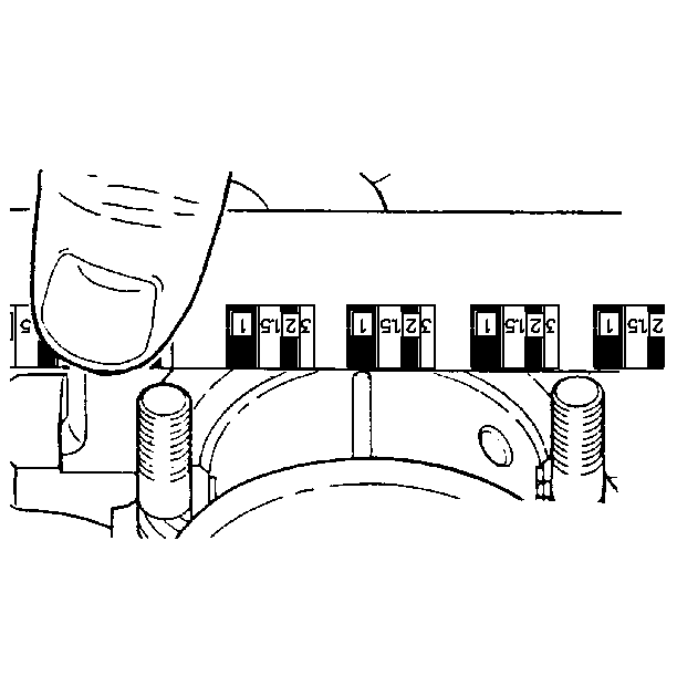
Notice: In order to prevent the possibility of cylinder block or crankshaft bearing cap damage, the crankshaft bearing caps are tapped into the cylinder block cavity using a brass, lead, or a leather mallet before the attaching bolts are installed. Do not use attaching bolts to pull the crankshaft bearing caps into the seats. Failure to use this process may damage a cylinder block or a bearing cap.
Important: Do not rotate the crankshaft.
Notice: Do not scrape, shim, or file bearing inserts. If the bearing surface of the insert is touched with bare fingers, the skin oil and acids will etch the bearing surface.
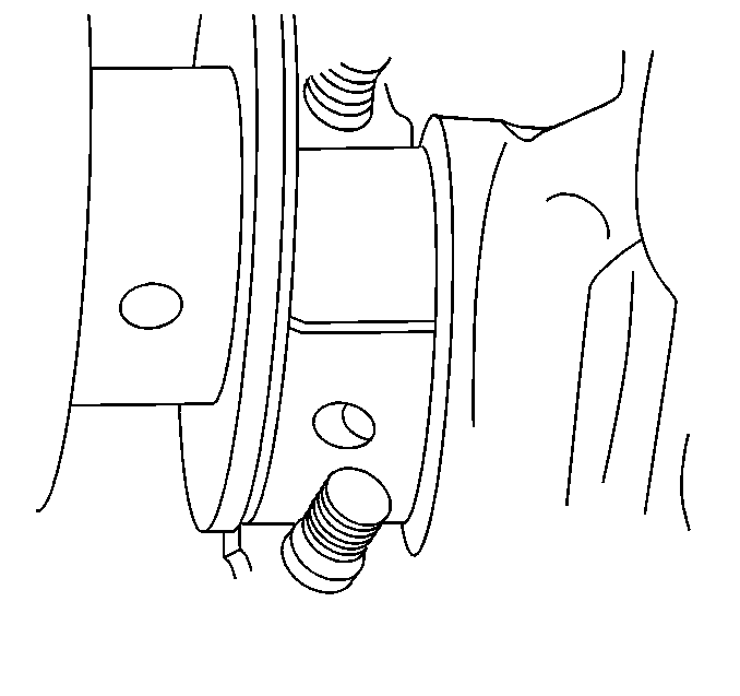
Bearing Installation Procedure
- Ensure that the bearing cap bolt holes and the cap mating surfaces are clean and dry.
- Dip the bearing cap bolts in clean engine oil.
- Lubricate the bearing surface with clean engine oil.
- Install the crankshaft.
- Install the crankshaft bearing caps. Tap gently into place with a brass or leather mallet.
- Install the bearing cap bolts. Finger tighten.
- Seat the crankshaft thrust bearing.
- Pry the connecting rods back and forth in order to check for binding. If necessary loosen and re-tighten the bearing cap.
- Measure the crankshaft end play.
- Measure the cnnecting rod side clearance.
Notice: Use connecting rod stud protectors or guide pins in order to avoid damage to the crankshaft journal.
Notice: In order to prevent the possibility of cylinder block or crankshaft bearing cap damage, the crankshaft bearing caps are tapped into the cylinder block cavity using a brass, lead, or a leather mallet before the attaching bolts are installed. Do not use attaching bolts to pull the crankshaft bearing caps into the seats. Failure to use this process may damage a cylinder block or a bearing cap.
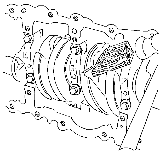
Tighten
Tighten the crankshaft main bearing cap bolts to 20 N·m
(15 lb ft) + 90 degrees using the J 36660-A
.
Tighten
Tighten the connecting rod bearing cap nuts to 25 N·m (18 lb ft)
+ 80 degrees using the J 36660-A
.
