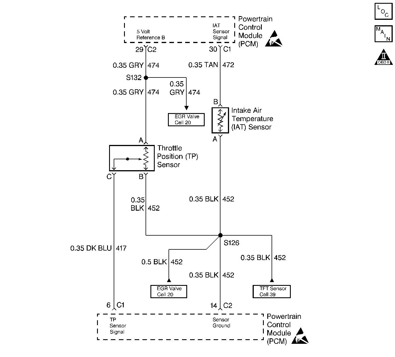
Circuit Description
The PCM supplies a 5V reference signal and a ground to the sensor. The TP sensor sends a voltage signal back to the PCM relative to the throttle plate opening. The voltage will vary from approximately 0.45Vat closed throttle, to over 4.5V at wide open throttle.
Conditions for Setting the DTC
| • | Engine is running. |
| • | TP sensor voltage is greater than 3.9 V for 5 seconds. |
| • | MAP is less than 65 kPa. |
| • | Engine speed is less than 1500 RPM. |
| • | DTC's P0107 or P0108 not set. |
| OR |
| • | TP sensor voltage is greater than 4.8 V. |
| • | DTC's P0107 or P0108 not set. |
Action Taken When the DTC Sets
| • | The Malfunction Indicator Lamp (MIL) will illuminate. |
| • | The PCM will record operating conditions at the time the diagnostic fails. This information will be stored in the Freeze Frame and Failure Records buffers. |
| • | A history DTC is stored. |
| • | Coolant fan turns ON. |
| • | The TP angle will default to 0% when the vehicle speed is less than 2 mph (3 km/h) and 10 % when the vehicle speed is greater than 2 mph (3 km/h) (The scan tool will display the defaulted value). |
Conditions for Clearing the MIL/DTC
| • | The MIL will turn OFF after three consecutive ignition cycles in which the diagnostic runs without a fault. |
| • | A history DTC will clear after 40 consecutive warm-up cycles without a fault. |
| • | The MIL/DTCs can be cleared by using the scan tool. |
Diagnostic Aids
If a DTC P0123 cannot be duplicated, the information included in the Freeze Frame data can be useful. Use the scan tool DTC information data to determine the status of the DTC. If the DTC occurs intermittently, use the DTC P0121 Diagnostic table in order to help isolate the problem.
| • | With the ignition ON and the throttle at closed position, the voltage should read between 0.20V and 0.90V and increase steadily to over 4.5V at wide open throttle. |
| • | DTCs P0123 and P0113 stored at the same time could be the result of an open sensor ground circuit. |
Test Description
Number(s) below refer to the step number(s) on the Diagnostic Table.
-
The Powertrain OBD System Check prompts the technician to complete some basic checks and store the freeze frame and failure records data on the scan tool if applicable. This creates an electronic copy of the data taken when the fault occurred. The information is then stored in the scan tool for later reference.
-
With the throttle closed, the TP sensor voltage should read less than 0.90V. If the TP sensor voltage does not read less than 0.90V check for a binding or sticking throttle cable.
-
With the TP sensor disconnected, the TP sensor voltage should less than 0.2V if the PCM and wiring are OK.
-
Probing the ground circuit with a test light checks the circuit for high resistance which will cause a DTC P0123 to set.
-
A shorted 5 volt reference circuit will also set additional DTC's.
-
Replacement PCM's must be reprogrammed. Refer to the latest Techline information for programming procedures.
Step | Action | Value(s) | Yes | No |
|---|---|---|---|---|
Was the Powertrain On-Board Diagnostic (OBD) System Check performed? | -- | Go to | ||
Is the TP sensor voltage greater than the specified value? | 1V | |||
3 |
Is the TP sensor voltage greater than the specified value? | 3.9V | ||
Disconnect the TP sensor electrical connector. Is the TP sensor voltage less than the specified value? | 0.2V | |||
Probe the TP sensor ground circuit at the TP sensor harness connector with a test light connected to B+. Does the test light illuminate? | -- | |||
6 | Check the TP sensor signal circuit for a short to voltage and repair as necessary. Was a repair necessary? | -- | ||
Check the TP sensor 5V reference circuit for a short to B+ and repair as necessary. Was a repair necessary? | -- | |||
8 | Check the TP sensor electrical connector for poor connection and replace the terminals as necessary. Was a repair necessary? | -- | ||
9 | Check the TP sensor ground circuit for a open and repair as necessary. Was a repair necessary? | -- | ||
10 | Replace the TP sensor. Is the action complete? | -- | -- | |
Replace the PCM. Is the action complete? | -- | -- | ||
12 |
Does the scan tool indicate that the diagnostic ran and passed? | -- | ||
13 | Check if any additional DTC's are set. Are any additional DTC's displayed that have not been diagnosed? | -- | Go to applicable DTC table | System OK |
