For 1990-2009 cars only
Tools Required
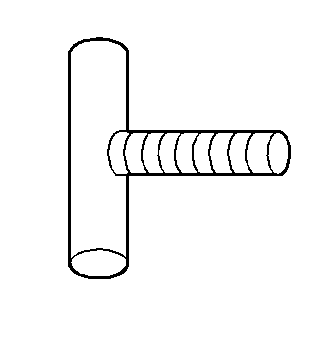
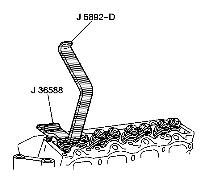
| • | J 36588 Valve Spring Compressor T-Bolt |
| • | J 5892-D Valve Spring Compressor |
| • | J 36017 Valve Guide Seal Remover |
| • | J 36660-A Torque Angle Meter |
Removal Procedure
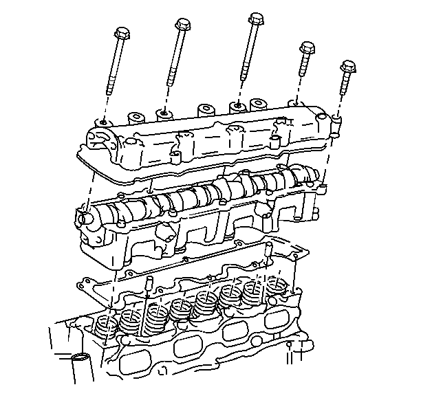
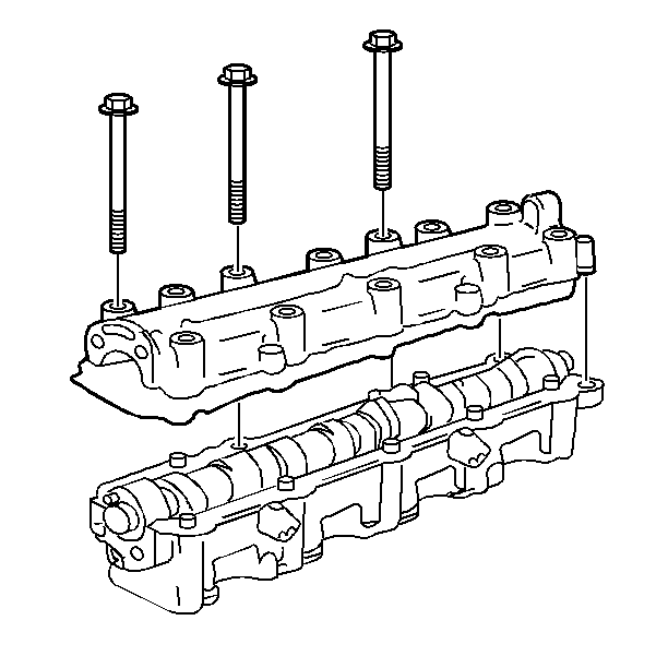
Important: Any time the camshaft housing to the cylinder head bolts are loosened or removed, the camshaft housing to the cylinder head gasket must be replaced.
- Disconnect the negative battery cable. Refer to Battery Negative Cable Disconnection and Connection in Engine Electrical.
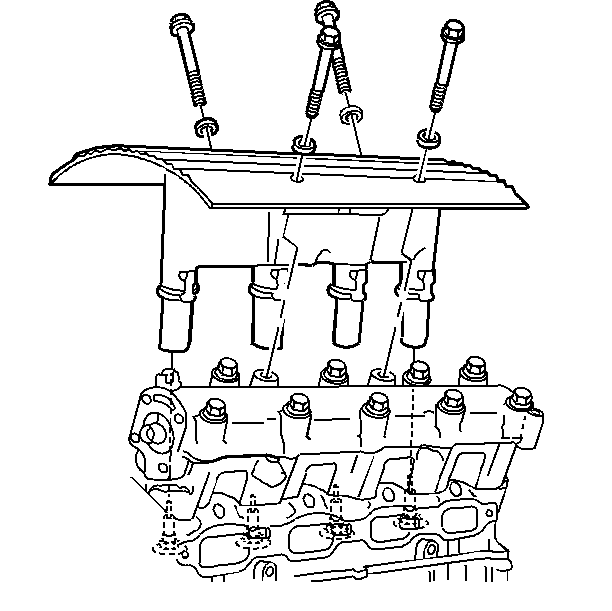
- Remove the ignition coil and module assembly. Refer to Ignition Control Module Replacement in Engine Controls.
- Disconnect the electrical connection from the oil pressure switch.
- Disconnect the timing chain housing at the camshaft housing, but do not remove it from the vehicle. Refer to Timing Chain Housing Replacement .
- Remove the camshaft housing. Refer to Exhaust Camshaft, Housing and Lifter Replacement or Intake Camshaft, Housing and Lifter Replacement .
- Remove the spark plug.
- Using a suitable adapter, apply air pressure to the cylinder.
- Compress the valve spring. Use the J 5892-D and the J 36588 .
- Disassemble the following components:
Notice: Turn the camshaft housing upside down as soon as it is removed from the cylinder head. The lifters will fall out of the camshaft housing if it is not turned upside down. the lifters can be damaged if they fall out and hit a hard surface.
Important: Use the reverse of the tightening procedure when loosening the camshaft housing to the cylinder head retaining bolts.
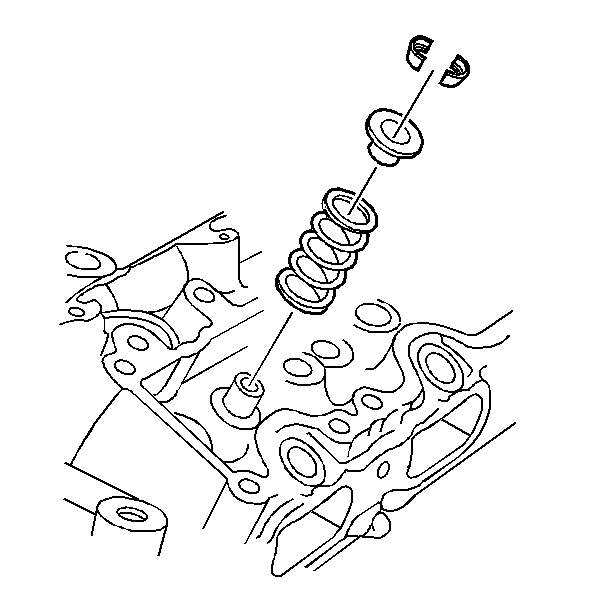
| • | The valve keys |
| • | The retainer |
| • | The spring |
| • | The valve seal using J 36017 |
| • | The rotator (intake) |
| • | The valve spring seat (exhaust) |
Installation Procedure
- Assemble the following components:
- Inspect for proper valve key seating.
- Remove the air line adapter.
- Install the spark plug.
- Install the camshaft housing. Refer to Exhaust Camshaft, Housing and Lifter Replacement or Intake Camshaft, Housing and Lifter Replacement .
- Install the timing chain housing to the camshaft housing and timing chain. Refer to Timing Chain Housing Replacement .
- Connect the electrical connection to the oil pressure switch.
- Install the ignition coil and module assembly. Refer to Ignition Control Module Replacement in Engine Controls.
- Connect the negative battery cable. Refer to Battery Negative Cable Disconnection and Connection in Engine Electrical.
| • | The rotator (intake) |
| • | The valve spring seat (exhaust) |
| • | A new, clean and dry valve seal. Push the seal on by hand in order to ensure that the seal is fully seated. |
| • | The valve keys |
Notice: Carefully roll the camshaft housing right side up as it is installed onto the cylinder head. The lifters can be damaged if they fall out and hit a hard surface.