Removal Procedure
- Remove the battery. Refer to Battery Replacement in Engine Electrical.
- Disconnect the IAT sensor and loosen the air duct hose from the intake plenum.
- Remove the push pin from the relay center, lift the relay center.
- Remove the air cleaner assembly. Refer to Air Cleaner Assembly Replacement in Engine Controls-2.2 L.
- Remove the upper radiator filler panel.
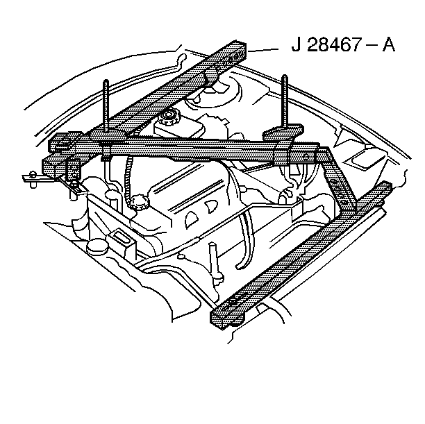
- Install the engine support fixture. Refer to Engine Support Fixture in Engine Mechanical-2.2 L.
- Disconnect the transaxle wiring harness from the transaxle and the PNP switch.
- Remove the screw from the front coolant pipe bracket to allow the freedom of movement.
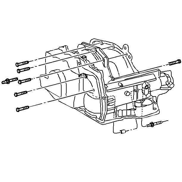
- Remove the 3 upper transaxle to engine bolts and the 1 stud.
- Remove the 2 top bolts from the transaxle mount.
- Raise and support the vehicle. Refer to Lifting and Jacking the Vehicle in General Information.
- Remove the tire and the wheel assemblies. Refer to Tire and Wheel Removal and Installation in Tires and Wheels.
- Remove the front fender liner. Refer to Front Fender Liner Replacement in Body Front End.
- Disconnect the engine strut from the lower engine mount. Refer to Engine Mount Strut Replacement in Engine Mechanical-2.2 L.
- Disconnect the front and rear oxygen senors and wiring harness from the shift cable bracket.
- Remove the wiring harness from the retaining clips.
- Remove the front exhaust pipe.
- Disconnect the wheel speed sensor wires from the both front wheels and unclip the clips from the frame.
- Remove the lower steering intermediate shaft pinch bolt.
- Remove the tie rod from the steering knuckle. Refer to Rack and Pinion Outer Tie Rod End Replacement in Front Suspension.
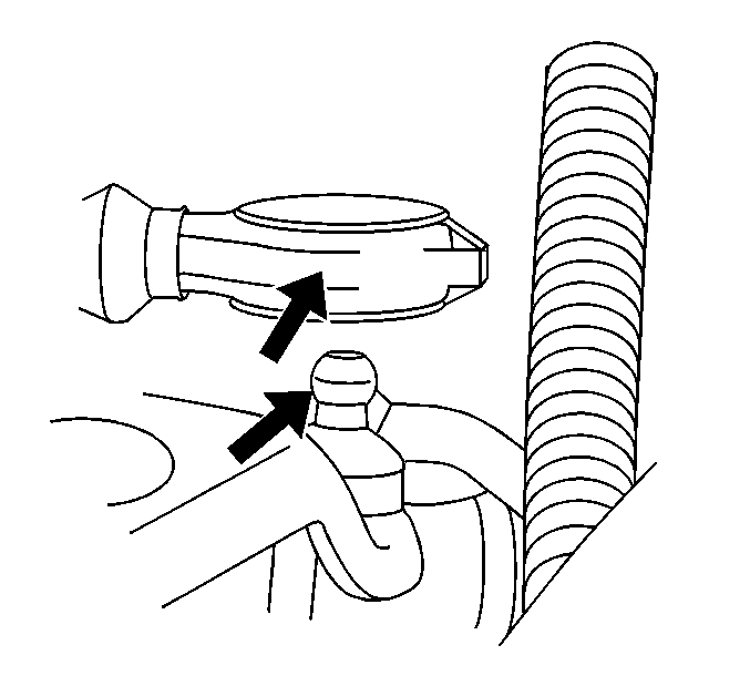
- Remove the ball joint from the steering knuckle. Refer to Lower Control Arm Ball Joint Replacement in Front Suspension.
- Remove the drive axles from the transaxle. Refer to Wheel Drive Shaft Replacement in Wheel Drive Shafts.
- Unclip the brake line from the retainers on the suspension support frame clips.
- Place a suitable drain pan in position to catch the power steering fluid as you remove the power steering lines from the rack and pinion assembly.
- Remove the bolt which retains the power steering line to the right side of the suspension support brace.
- Remove the front suspension support brace bolts.
- Remove the support brace.
- With the aid of an assistant remove the lower suspension support.
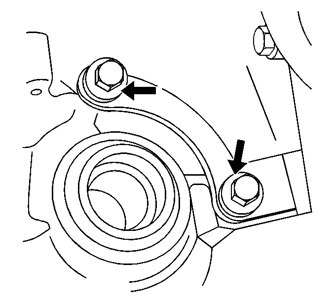
- Remove the 2 bolts which hold the transaxle to engine support brace to the transmission at the right side of the transaxle output shaft.
- Disconnect the shift cable from the shift linkage.
- Disconnect the cable from the bracket.
- Remove the flywheel inspection cover.
- Remove the starter. Refer to Starter Motor Replacement in Engine Electrical.
- Mark the relationship of the flywheel to the torque converter for reassembly.
- Remove the torque converter to flywheel bolts.
- Remove the transaxle cooler lines by removing the nut holding the bracket to the transaxle case.
- Disconnect the VSS wiring harness from the sensor.
- Disconnect the transaxle output shafts from the transaxle and support in an out of the way position with mechanics wire.
- Remove the 2 bolts which retain the transaxle bracket to the body.
- Remove the 2 bolts retaining the bracket to the transaxle.
- Remove the wiring harness from the body.
- Lower the vehicle.
- Remove the 2 bolts from the transaxle to body bracket.
- Lower the transaxle with the engine support fixture enough to remove the transaxle.
- Raise the vehicle.
- Remove the two retaining bolts and the bracket.
- Remove the 2 transaxle to engine bolts.
- Support the transaxle with a suitable jack.
- Separate the engine and the transaxle.
- Remove the transaxle from the vehicle.
- Flush the transmission cooler and lines. Refer to Transmission Fluid Cooler Flushing and Flow Test .
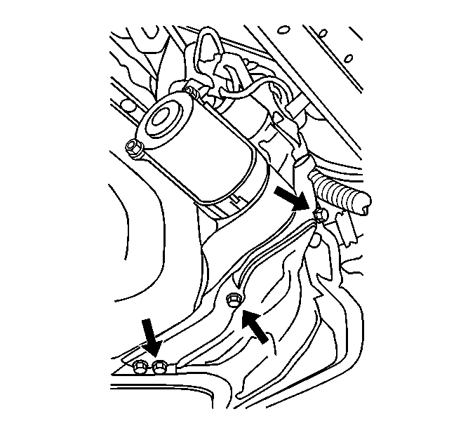
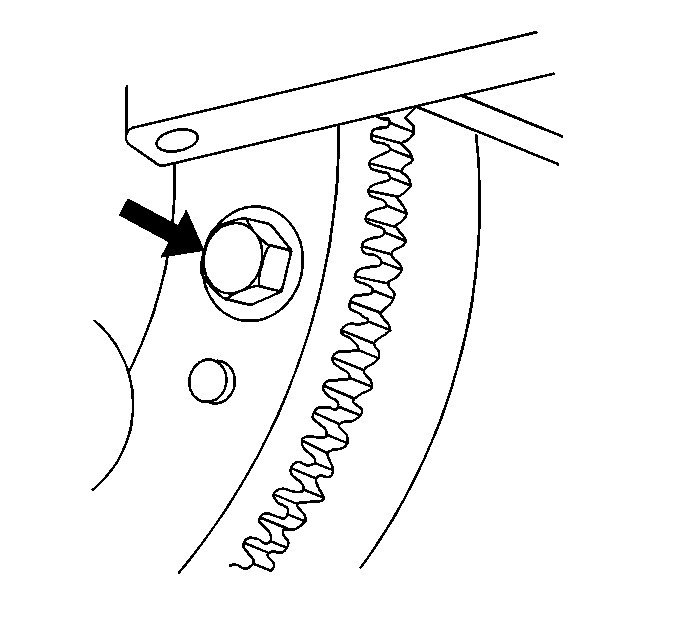
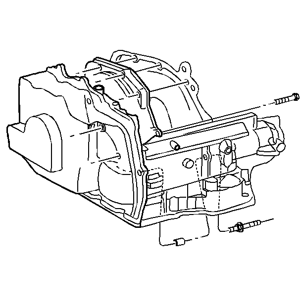
Installation Procedure
- Place a thin film of chassis grease GM P/N 1051344, or the equivalent, on the torque converter pilot hub.
- Ensure that the torque converter is properly seated in the oil pump.
- Position the transaxle in the vehicle.
- Install the lower transaxle to engine bolts and 2 studs.
- Install the transaxle to body bracket bolts.
- Lower the vehicle.
- Use the engine support fixture to raise the transaxle.
- Install the 2 bolts through the unibody frame into the transaxle to engine mount bracket.
- Raise the vehicle.
- Reposition the wiring harness into its clips on the body rail.
- Install the drive axles to the transaxle. Refer to Wheel Drive Shaft Replacement in Wheel Drive Shafts.
- Install the wiring harness to the VSS.
- Connect the transaxle cooler pipes to the transaxle.
- Install the torque converter to flywheel bolts.
- Install the starter. Refer to Starter Motor Replacement in Engine Electrical.
- Install the battery cable to the starter and the nut.
- Install the starter wire and the nut to the starter solenoid.
- Install the flywheel inspection cover.
- Connect the shift cable to the bracket and the lever.
- With the aid of an assistant install the front suspension support assembly, rack and pinion assembly into place with the 6 bolts.
- Install the left side suspension support brace and bolts.
- Install and tighten the power steering lines to the rack and pinion steering gear.
- Install the bolt that secures the power steering lines to the front suspension support assembly.
- Reconnect the ball joints to the steering knuckles and the nuts.
- Install the cotter pin in both the balls joints.
- Reconnect the tie rod ball stud and nut to the steering knuckle.
- Install the lower steering column pinch bolt.
- Reroute and clip the wheel speed sensor wiring into the proper position on both sides.
- Install the catalytic converter flange attaching bolts.
- Install the front pipe to the manifold exhaust and the nuts.
- Route and clip the rear oxygen senor and wires in there proper position.
- Lower the vehicle to loosen the J 28476-B and allow the engine to assume its proper position.
- Raise the vehicle.
- Install the right side suspension support bolts.
- Install the front fender liner. Refer to Front Fender Liner Replacement in Body Front End.
- Install the tire and the wheel assemblies. Refer to Tire and Wheel Removal and Installation in Tires and Wheels.
- Lower the vehicle.
- Install the upper transmission to engine bolts.
- Install the upper transaxle to engine bolts and stud.
- Install the engine wiring harness grounds to the transaxle to engine mount stud and nut.
- Remove the engine support fixture. Refer to Engine Support Fixture in Engine Mechanical-2.2 L.
- Install the heater pipe screw.
- Connect the electrical connectors to the PNP switch.
- Install the shift linkage to the transaxle.
- Install the radiator filler panel to the vehicle.
- Install the air cleaner assembly. Refer to Air Cleaner Assembly Replacement in Engine Controls-2.2 L.
- Connect the IAT sensor.
- Install the battery. Refer to Battery Replacement in Engine Electrical.
- Inspect the transmission oil level. Refer to Transmission Fluid Check .
- Apply the brakes. Start the engine. Shift the transaxle from R (Reverse) to D (Drive).
- Road test the vehicle.


Notice: Use the correct fastener in the correct location. Replacement fasteners must be the correct part number for that application. Fasteners requiring replacement or fasteners requiring the use of thread locking compound or sealant are identified in the service procedure. Do not use paints, lubricants, or corrosion inhibitors on fasteners or fastener joint surfaces unless specified. These coatings affect fastener torque and joint clamping force and may damage the fastener. Use the correct tightening sequence and specifications when installing fasteners in order to avoid damage to parts and systems.
Tighten
Tighten the bolts and studs to 90 N·m (66 lb ft).
Tighten
Tighten the bolts to 90 N·m (66 lb ft).

Tighten
Tighten the cooler pipes to 8 N·m (71 lb ft).

Tighten
Tighten the torque converter bolts to 62 N·m (46 lb ft).

Tighten
Tighten the starter bolts to 50 N·m (37 lb ft).
Tighten
Tighten the nut to 15 N·m (11 lb ft).
Tighten
Tighten the nut to 11 N·m (8 lb ft).
Notice: Use the correct fastener in the correct location. Replacement fasteners must be the correct part number for that application. Fasteners requiring replacement or fasteners requiring the use of thread locking compound or sealant are identified in the service procedure. Do not use paints, lubricants, or corrosion inhibitors on fasteners or fastener joint surfaces unless specified. These coatings affect fastener torque and joint clamping force and may damage the fastener. Use the correct tightening sequence and specifications when installing fasteners in order to avoid damage to parts and systems.
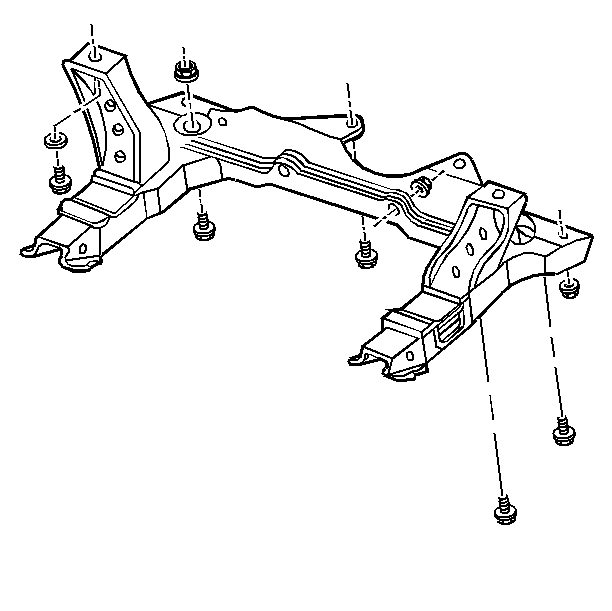
Tighten
Tighten the 6 bolts to 110 N·m (71 lb ft).
Tighten
Tighten the brace bolts to 72 N·m (53 lb ft).
Tighten
Tighten the power steering bolts to 27 N·m (20 lb ft).
Tighten
Tighten the bolt to 8 N·m (71 lb ft).
Tighten
Tighten the nuts to 60 N·m (50 lb ft) plus 180 degrees.
Tighten
Tighten the tie rod ball stud nut to 45 N·m (33 lb ft).
Tighten
Tighten the pinch bolt to 40 N·m (30 lb ft).
Tighten
Tighten the bolts to 30 N·m (22 lb ft).
Tighten
Tighten the nuts to 45 N·m (33 lb ft).

Tighten
Tighten the bolts to 72 N·m (53 lb ft).

Tighten
Tighten all of the bolts to 90 N·m (66 lb ft).
Tighten
Tighten the bolts and stud to 90 N·m (66 lb ft).
Tighten
Tighten the nut to 8 N·m (71 lb in).


