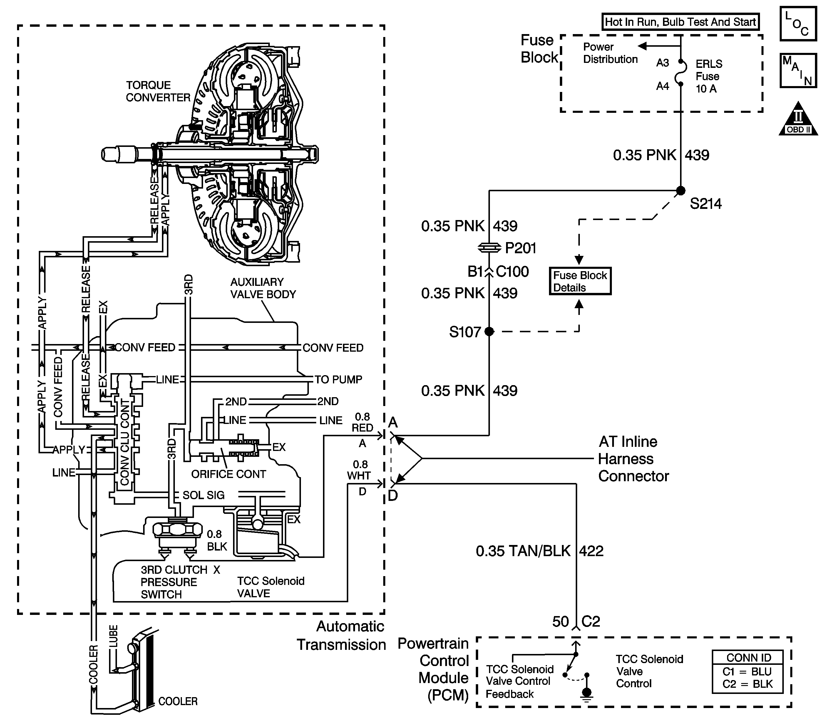
Circuit Description
The torque converter clutch solenoid valve (TCC solenoid valve) receives ignition voltage from the fuse panel. The normally-open 3rd clutch pressure switch interrupts the ground path from the TCC solenoid valve. The powertrain control module (PCM) activates the TCC solenoid valve by grounding the circuit through an internal switch in the PCM. Although the PCM commands the TCC solenoid valve On, the converter clutch does not apply until the 3rd clutch oil (3rd clutch engaged) closes the pressure switch, completing the circuit. Activating the TCC solenoid valve blocks exhaust fluid. This moves the converter clutch control valve to the applied position, and provides fluid pressure to engage the torque converter clutch.
When the PCM detects low TCC slip and the torque converter clutch is commanded off, then DTC P0742 sets. DTC P0742 is a type B DTC.
Conditions for Running the DTC
| • | No TP sensor DTC P0121, P0122 or P0123. |
| • | The PCM has commanded the TCC off. |
| • | The engine speed is 1,500-4,000 RPM. |
| • | Engine torque is greater than 13 N·m (10 lb ft). |
| • | Time since the last gear selector lever change has been more than 6 seconds. |
| • | The speed ratio is 0.9-1.375. |
| • | The throttle angle is greater than 8 percent. |
| • | The slip speed is -20 to +20 RPM for 10 seconds. |
| • | The vehicle speed is 56-120 km/h (35-75 mph). |
Conditions for Setting the DTC
The PCM detects two or more counts of the TCC being stuck on.
Action Taken When the DTC Sets
| • | The PCM illuminates the malfunction indicator lamp (MIL) during the second consecutive trip in which the conditions for setting the DTC are met. |
| • | The PCM stores DTC P0742 in PCM history during the second consecutive trip in which the Conditions for Setting the DTC are met. |
Conditions for Clearing the MIL/DTC
| • | The PCM turns off the MIL during the third consecutive trip in which the diagnostic test runs and passes. |
| • | A scan tool can clear the MIL/DTC. |
| • | The PCM clears the DTC from PCM history if the vehicle completes 40 consecutive warm-up cycles without an emission-related diagnostic fault occurring. |
Diagnostic Aids
If the vehicle stalls repeatedly, the TCC is mechanically stuck on.
Test Description
The numbers below refer to the step numbers on the diagnostic table.
-
This step determines whether the stuck on condition is due to an electrical condition or a mechanical condition.
-
This step tests for a short to ground on the TCC solenoid valve control circuit (CKT 422) between the automatic transmission wiring harness and the PCM.
Step | Action | Value(s) | Yes | No | ||||||
|---|---|---|---|---|---|---|---|---|---|---|
1 | Did you perform the Powertrain Diagnostic System Check? | -- | Go to Diagnostic System Check - Engine Controls in Engine Controls - 2.2 L or Diagnostic System Check - Engine Controls in Engine Controls - 2.4 L | |||||||
Important: Before clearing the DTC, use the Scan Tool in order to record the DTC Freeze Frame and Failure Records. Using the Clear Info function erases the Freeze Frame and Failure Records from the PCM. Important: Record the TCC slip speed when the transmission is in third gear, with the TCC enabled or engaged. Is the TCC slip speed outside the range shown? | -20 to +20 RPM | |||||||||
Is the test lamp ON? | -- | |||||||||
4 | Test the TCC solenoid valve control circuit (CKT 422) between the AT inline harness connector and the PCM for a short to ground. Refer to Circuit Testing and Wiring Repairs in Wiring Systems. Did you find and correct the condition? | -- | ||||||||
5 | Replace the PCM. Refer to Powertrain Control Module Replacement in Engine Controls - 2.2 L or Powertrain Control Module Replacement in Engine Controls - 2.4 L. Did you complete the replacement? | -- | -- | |||||||
6 |
Refer to Transmission Overhaul in the 3T40-E Section of the Transmission Unit Repair Manual. Is the circuit resistance within the specified range? | 19-31 ohms | ||||||||
7 | Test the ignition voltage circuit (CKT 439) from terminal A of the AT inline harness connector to the 3rd clutch pressure switch for a short to ground. Refer to Circuit Testing and Wiring Repairs in Wiring Systems. Did you find and correct the condition? | -- | ||||||||
8 | Replace the TCC solenoid valve. Refer to TCC Solenoid and Switches Replacement. Did you complete the replacement? | -- | -- | |||||||
9 | TCC release oil circuit blocked. Inspect for the following conditions:
Did you find and correct the condition? | -- | ||||||||
10 | The TCC solenoid valve may be stuck closed (not exhausting).
Refer to TCC Solenoid and Switches Replacement. Did you find and correct the condition? | -- | ||||||||
11 | The converter clutch control valve may be stuck on.
Refer to Transmission Overhaul in the 3T40-E Section of the Transmission Unit Repair Manual. Did you find and correct the condition? | -- | ||||||||
12 | Inspect the torque converter clutch. If the TCC is mechanically applied (stuck on), replace the torque converter. Refer to Transmission Overhaul in the 3T40-E Section of the Transmission Unit Repair Manual. Did you find and correct the condition? | -- | -- | |||||||
13 | Perform the following procedure in order to verify the repair:
Has the test run and passed? | -- | System OK |
