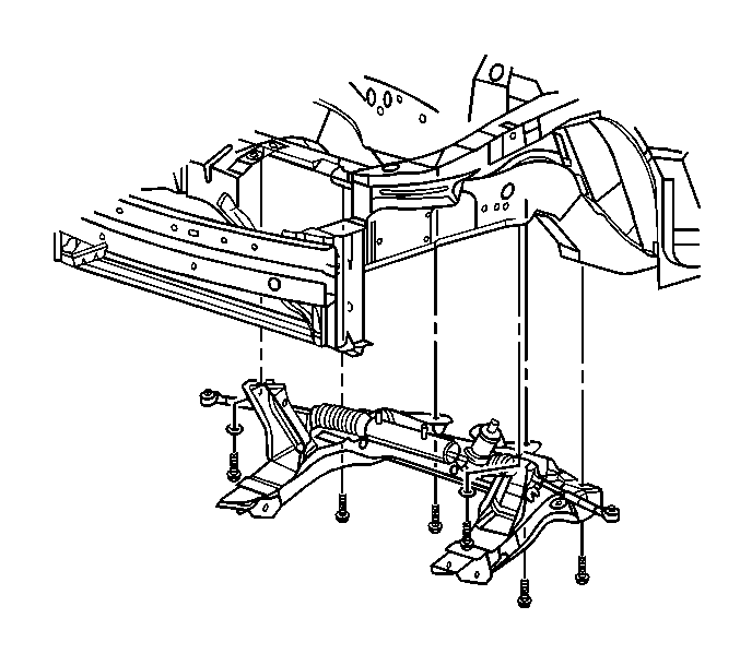
For 1990-2009 cars only
Removal Procedure
- Raise and support the vehicle. Refer to Lifting and Jacking the Vehicle in General Information.
- Remove the tire and wheel assemblies. Refer to Tire and Wheel Removal and Installation in Tires and Wheels.
- Remove the front fender liners. Refer to Front Fender Liner Replacement in Body Front End.
- Remove the engine strut from the lower engine mount and frame. Refer to Engine Mount Strut Replacement in Engine Mechanical - 2.2L (L61) .
- Remove the front exhaust pipe. Refer to Intermediate Pipe Replacement in Engine Exhaust.
- Disconnect the ABS harness from the lower control arms.
- Disconnect the ball joints from the steering knuckles. Refer to Stabilizer Shaft Replacement .
- Disconnect the tie rods from the steering knuckles. Refer to Rack and Pinion Outer Tie Rod End Replacement in Power Steering System.
- On vehicles with a brake pipe running along the crossmember, disconnect the brake pipe from the retainers.
- Remove the power steering gear to crossmember mounting bolts.
- Secure the power steering gear to the body, taking care not to over extend the intermediate shaft.
- Remove the front suspension support brace. Refer to Front Suspension Support Brace Replacement .
- Support the crossmember , using suitable jack stands.
- Remove the front suspension crossmember mounting bolts.
- Lower the crossmember from the vehicle.
- If replacing the crossmember, remove the following components:

| • | The lower control arms. Refer to Lower Control Arm Replacement in Front Suspension. |
| • | The stabilizer shaft. Refer to Stabilizer Shaft Replacement . |
Installation Procedure
- If replacing the crossmember, Install the following components:
- Using suitable jack stands, raise the crossmember to the vehicle.
- Install the front suspension crossmember mounting bolts.
- Tighten the left rear outboard bolt to 110 N·m (81 lb ft) plus an additional 90 degrees.
- Tighten the right rear outboard bolt to 110 N·m (81 lb ft) plus an additional 90 degrees.
- Tighten the front upper bolts to 110 N·m (81 lb ft) plus an additional 90 degrees.
- Tighten the rear inboard bolts to 110 N·m (81 lb ft) plus an additional 90 degrees.
- Install the front suspension support brace. Refer to Front Suspension Support Brace Replacement .
- Reposition the steering gear to the crossmember.
- Install the power steering gear to crossmember mounting bolts.
- On vehicles with the brake pipe running along the support frame, install the brake pipe into the retainers.
- Connect the tie rods to the steering knuckle. Refer to Rack and Pinion Outer Tie Rod End Replacement in Power Steering System.
- Connect the lower control arms to the steering knuckles. Refer to Lower Control Arm Ball Joint Replacement .
- Connect the ABS harness to the lower control arms. Refer to Front Wheel Speed Sensor Replacement in Antilock Brake System.
- Install the front exhaust pipe. Refer to Intermediate Pipe Replacement in Engine Exhaust.
- Install the engine strut to the lower engine mount and frame. Refer to Engine Mount Strut Replacement in Engine Mechanical - 2.2L (L61).
- Install the front fender liners. Refer to Front Fender Liner Replacement in Body Front End.
- Install the tire and wheel assemblies. Refer to Tire and Wheel Removal and Installation in Tires and Wheels.
| • | The stabilizer shaft. Refer to Stabilizer Shaft Replacement . |
| • | The lower control arms. Refer to Lower Control Arm Replacement in Front Suspension. |

Notice: Refer to Fastener Notice in the Preface section.
Tighten
Tighten
Tighten the bolts to 120 N·m (89 lb ft).
