Steering Shaft, Lower Bearing, and Jacket Replacement Tilt
Tools Required
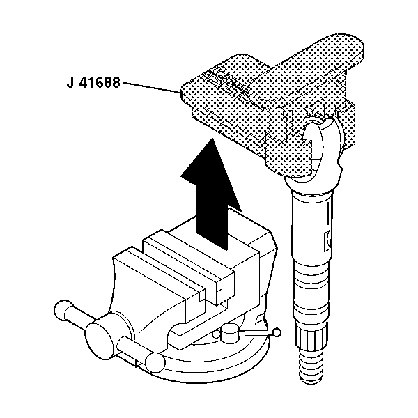
J 41688 Centering Sphere Installer
Removal Procedure
- Disable the SIR system. Refer to SIR Disabling and Enabling in SIR.
- Remove the steering column jacket. Refer to Steering Column Jacket Replacement .
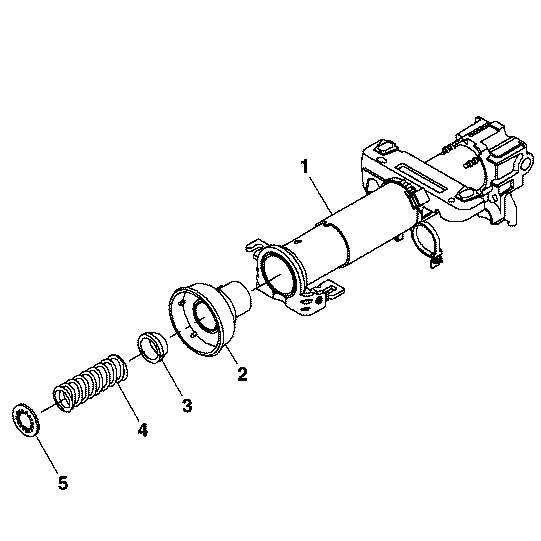
- Remove the lower spring retainer (5) and discard.
- Remove the lower bearing spring (4).
- Remove the lower bearing seat (3).
- Remove the adapter and bearing assembly (2) from steering column jacket assembly (1).
- Remove the steering shaft assembly from the steering column jacket assembly.
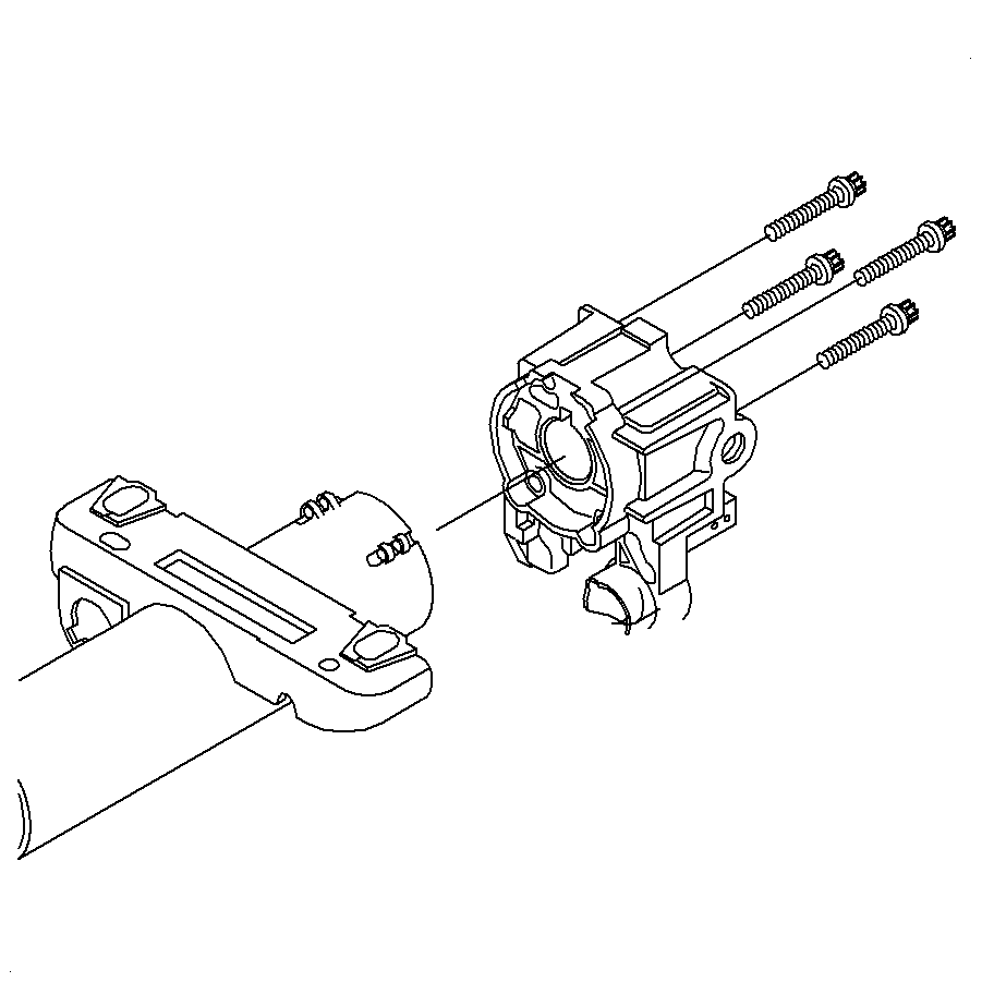
- Remove the 4 support screws and discard.
- Remove the steering column support assembly from the steering column jacket assembly.
- Tilt the upper shaft assembly (1) 90 degrees to the lower steering shaft assembly (2) and disengage.
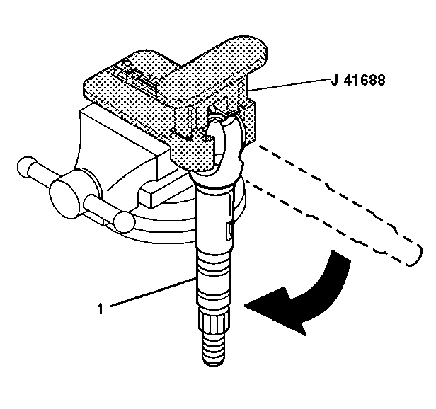
- Insert the race and upper shaft assembly (1) into J 41688 .
- Insert J 41688 into a vise.
- Rotate the driver 90 degrees in the counterclockwise direction in order to disengage the centering sphere from the race and upper shaft assembly.
- Remove the race and upper shaft assembly (1) from J 41688 .
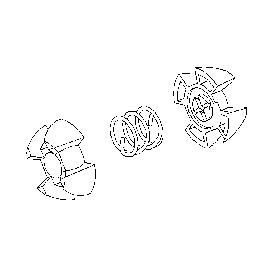
- Remove the shaft preload spring and the centering sphere fromJ 41688 .
- If necessary, discard the old centering sphere and the old shaft preload spring.
- Remove the joint preload spring from the centering sphere.
Caution: Refer to SIR Caution in the Preface section.
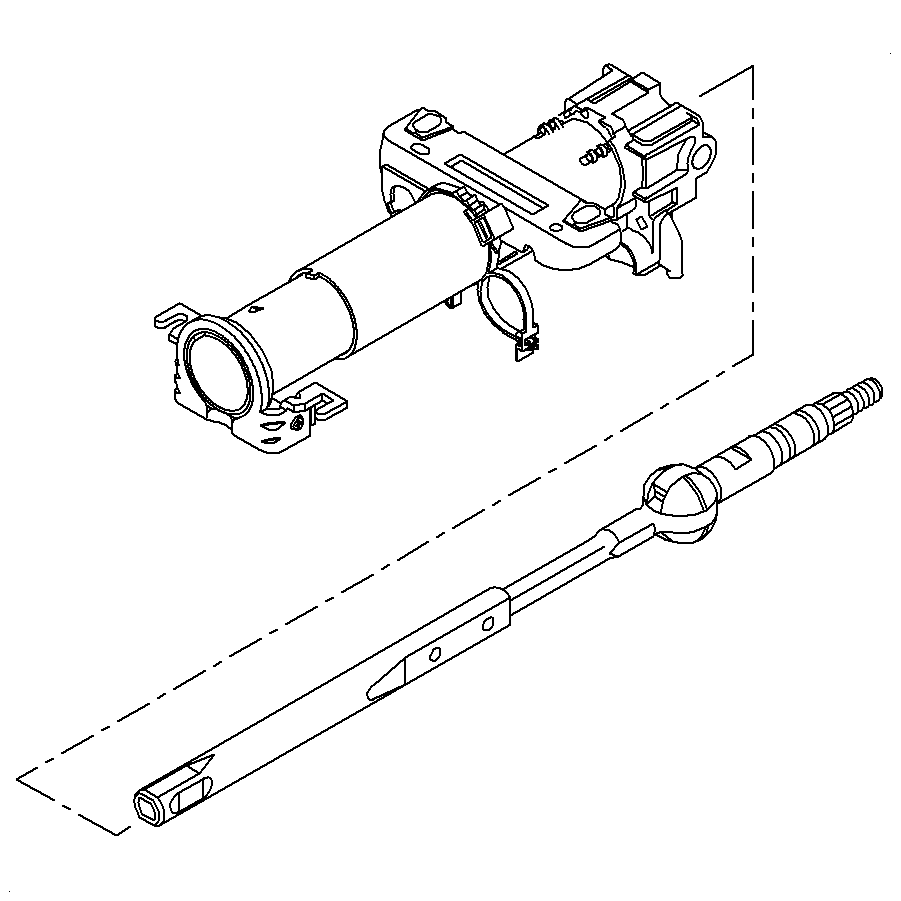
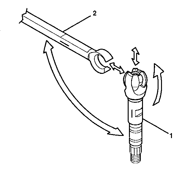
Important: Mark the upper shaft assembly and the lower steering shaft assembly to ensure proper assembly. Failure to assemble properly will cause the steering wheel to be turned 180 degrees.
Installation Procedure
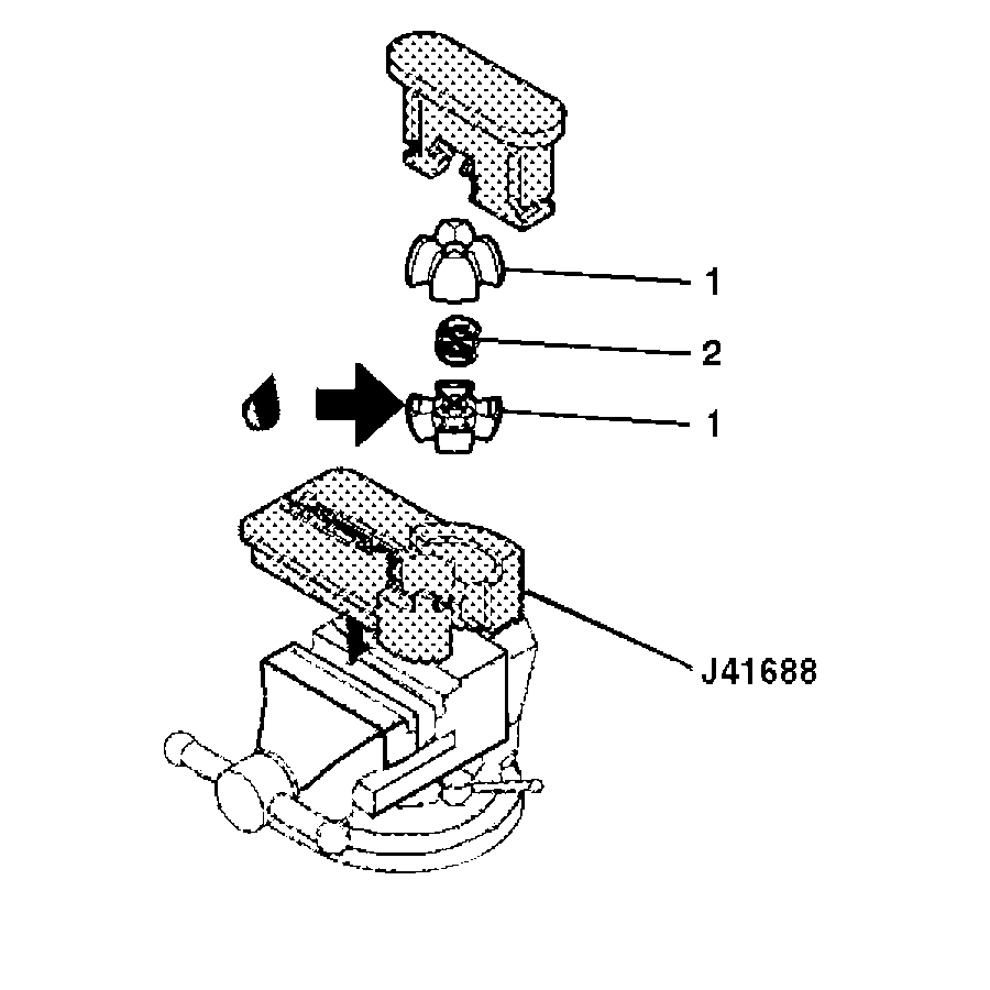
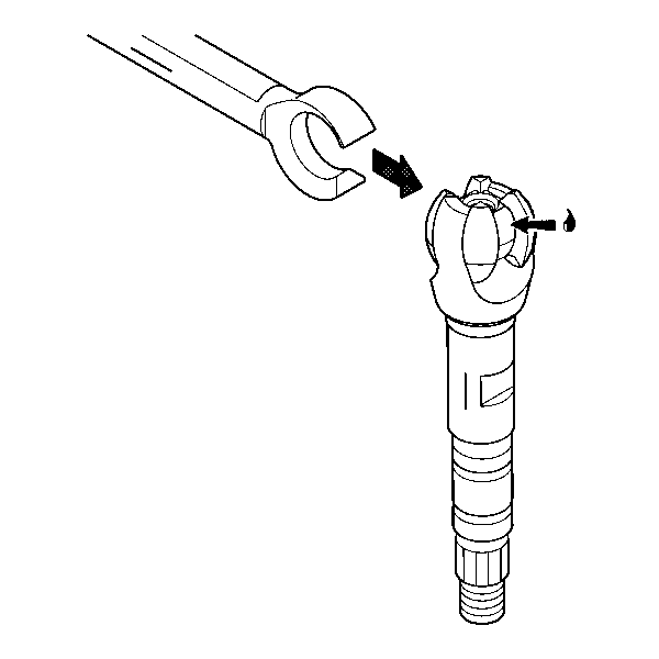
- Lubricate the centering sphere (1) with GM P/N 12345718 (Canadian P/N 10953516).
- Install the centering sphere (1) and the joint preload spring (2) into J 41688 .
- Compress the centering sphere and joint preload spring with J 41688 .
- Install the upper shaft assembly.
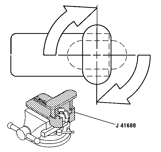
- After the race and upper shaft assembly (1) is firmly attached to the centering sphere, rotate the shaft 90 degrees downward in order to lock the centering sphere in place.
- Remove the centering sphere installer and the race and upper shaft assembly from the vise.
- Disassemble J 41688 by separating the base. After the tool is disassembled, remove the race and upper shaft from J 41688 .
- Lubricate the centering sphere with GM P/N 12345718 (Canadian P/N 10953516).
- Using the alignment marks from the disassemble procedure, tilt the upper and lower shafts 90 degrees to each other and engage.
- Install the steering column support assembly to the steering column jacket assembly with the 4 support screws.
- Install the steering shaft assembly into the steering column support assembly.
- Install the adapter and bearing assembly (2) to the steering column jacket assembly (1). Position the tab on the adapter and bearing assembly with the slot in steering column jacket assembly and push together.
- Install the lower bearing seat (3).
- Install the lower bearing spring (4).
- Install the new lower spring retainer (5).
- Install the steering column jacket. Refer to Steering Column Jacket Replacement .
- Enable the SIR system. Refer to SIR Disabling and Enabling in SIR.

Notice: Refer to Fastener Notice in the Preface section.

Tighten
Tighten the screws to 8 N·m (71 lb in).


When installing, compress the lower bearing spring (4) to the length of 23.5 mm (0.93 in) between the lower bearing seat (3) and the lower spring retainer (5).
Caution: Improper routing of the wire harness assembly may damage the inflatable restraint steering wheel module coil. This may result in a malfunction of the coil, which may cause personal injury.
Steering Shaft, Lower Bearing, and Jacket Replacement Standard
Removal Procedure
- Disable the SIR system. Refer to SIR Disabling and Enabling in SIR.
- Remove the steering column jacket. Refer to Steering Column Jacket Replacement .
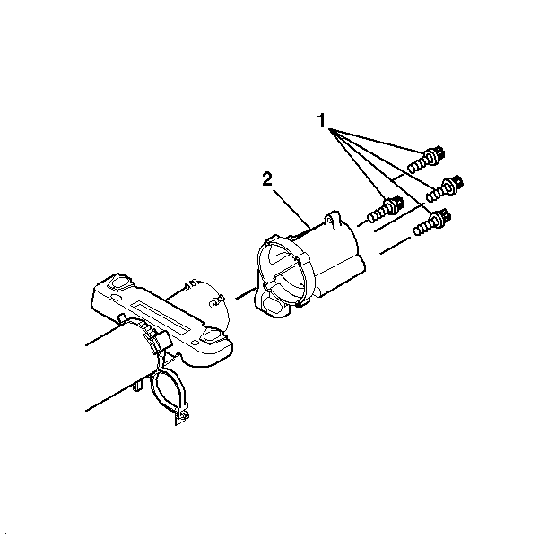
- Remove and discard the 4 support screws (1).
- Remove the support mounting adapter (2).
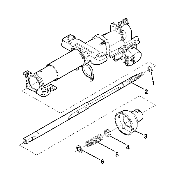
- Remove and discard the lower spring retainer (6).
- Remove the lower bearing spring (5).
- Remove the lower bearing seat (4).
- Remove the adapter and bearing assembly (3).
- Remove and discard the bearing retainer (1).
- Remove the steering shaft assembly (2) from the steering column jacket.
Caution: Refer to SIR Caution in the Preface section.
Installation Procedure
- Install the support mounting bracket (2).
- Lubricate the new support screws (1) with LOCTITE® 242, GM P/N 123455382 (Canadian P/N 10953489).
- Install 4 new support screws (1).
- Install the steering shaft assembly (2) into the steering column jacket assembly.
- Install the new bearing retainer (1).
- Install the adapter and bearing assembly (3).
- Install the lower bearing seat (4).
- Install the lower bearing spring (5).
- Install the new lower spring retainer (6).
- Install the steering column jacket. Refer to Steering Column Jacket Replacement .
- Enable the SIR system. Refer to SIR Disabling and Enabling in SIR.
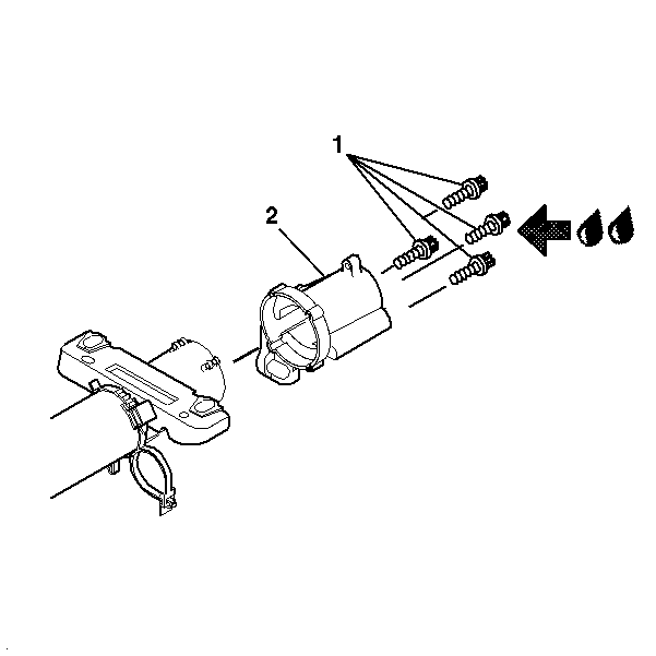
Notice: Refer to Fastener Notice in the Preface section.
Tighten
Tighten the screws to 8 N·m (71 lb in).

Important: The bearing retainer must be seated correctly on the steering shaft.
Important: When installing, compress the lower bearing spring (5) to the length of 23.5 mm (0.93 inches) between the lower bearing seat (4) and the lower spring retainer (6).
Caution: Improper routing of the wire harness assembly may damage the inflatable restraint steering wheel module coil. This may result in a malfunction of the coil, which may cause personal injury.
