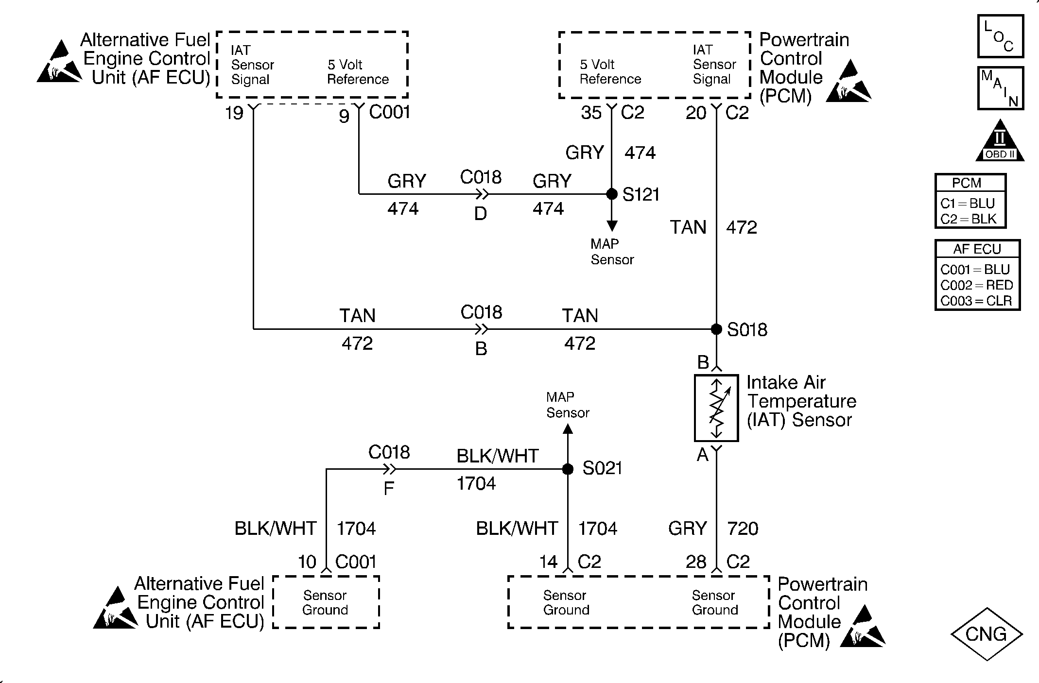
Circuit Description
The Intake Air Temperature (IAT) sensor is a thermo resistor located in the fresh air duct. The sensor monitors the temperature of the air entering the throttle body. The PCM applies five volts to the sensor on a five volt reference circuit. When the air is cool, resistance in the sensor measures high and the ECU senses a high voltage signal. If the air is warm, the sensor resistance measures low and the ECU senses a low voltage signal.
This is a type B DTC.
Conditions for Setting the DTC
The following conditions will set the DTC:
| • | The vehicle is in the CNG operation mode. |
| • | The vehicle speed is greater than 1 mph. |
| • | The engine run time is greater than 100 seconds. |
| • | The IAT voltage is below 0.019 volt. |
Action Taken When the DTC Sets
The ECU sets the DTC 23 after two consecutive driving cycles with the fault active.
Conditions for Clearing the MIL/DTC
The ECU turns the MIL off after three consecutive driving trips without a fault condition present. A DTC will clear if no fault conditions have been detected for 40 warm-up cycles (coolant temperature has risen 72°F (40°C) from the start-up coolant temperature and the engine coolant temperature exceeds 160°F (70°C) during that same ignition cycle) or the code clearing procedure has been used.
Diagnostic Aids
Always diagnose ANY PCM codes that are present before beginning this diagnostic procedure.
A scan tool indicates the temperature of the ambient air entering the throttle body. The air temperature should read very close to the temperature of the outside air. The air temperature should rise gradually as the engine warms up and the underhood temperature increases. Inspect for poor connections at the ECU and the IAT sensor by wiggling the connector gently and monitoring the IAT voltage on a DVOM connected to the ECU connector. Repair the connector if the voltage varies.
A sensor may become skewed or mis-scaled. The Temperature vs. Resistance value table will help to detect a skewed sensor. Refer to Temperature vs. Resistance in Engine Controls -- 2.2L in the J Platform Service Manual.
Test Description
The number(s) below refer to the step number(s) on the diagnostic table.
Important: Use the same diagnostic test equipment for all of the measurements.
-
With connector C018 disconnected and the voltage still present, this eliminates the ECU and the AF wire harness as the possible cause of the fault.
-
If the IAT sensor circuit voltage measures less than 0.019 volt, the conditions for the DTC are still present and the problem is not intermittent.
Step | Action | Value(s) | Yes | No |
|---|---|---|---|---|
1 | Was the AF Powertrain OBD System Check performed? | -- | Go to Step 2 | Go to Alternative Fuels (AF) Powertrain On Board (OBD) System Check |
2 |
Is the IAT sensor value greater than the specified value? | 128°C (262°F) | Go to Step 3 | Go to Step 4 |
3 |
Does the scan tool display an IAT sensor value greater than the specified value? | 128°C (262°F) | Go to Step 8 | Go to Step 6 |
Using a DVOM, backprobe the IAT sensor signal in the ECU connector. Does the DVOM display the IAT sensor signal less than the specified value? | 0.019 V | Go to Step 5 | Go to Step 10 | |
Is there continuity? | -- | Go to Step 6 | Go to Step 11 | |
6 |
Was a problem found? | -- | Go to Step 11 | Go to Step 7 |
7 | Replace the ECU. Refer to Engine Control Unit Replacement . Is the action complete? | -- | Go to Step 16 | -- |
8 |
Is the IAT sensor value less than the specified value? | -30°C (-22°F) | Go to Step 14 | Go to Step 9 |
9 | Connect a test light to B+ and probe the IAT sensor signal circuit terminal in cavity B at the IAT sensor electrical connector. Does the test light illuminate? | -- | Go to Step 12 | Go to Step 15 |
10 | The DTC is intermittent. If no additional DTCs are stored, refer to Diagnostic Aids. If additional DTCs were stored, refer to those tables. Are any additional DTCs set? | -- | Go to the applicable DTC table | Go to Diagnostic Aids |
11 | Repair the circuit as needed. Refer to Wiring Repairs in Engine Controls - 2.2L in the J Platform Service Manual. Is the repair complete? | -- | Go to Step 16 | -- |
12 |
Does the test light illuminate? | -- | Go to Step 13 | Go to Step 15 |
13 | Repair the short to the ground in the IAT sensor signal circuit. Is the repair complete? | -- | Go to Step 16 | -- |
14 | Replace the IAT sensor. Refer to IAT Sensor Replacement in Engine Controls - 2.2L in the J Platform Service Manual. Is the repair complete? | -- | Go to Step 16 | -- |
15 |
Is the repair complete? | -- | Go to Step 16 | -- |
16 |
Did the diagnostic run and pass? | -- | Go to Step 17 | Go to Step 2 |
17 | Are any ECU or PCM DTCs displayed that have not been diagnosed? | -- | Go to the applicable DTC table | System OK |
