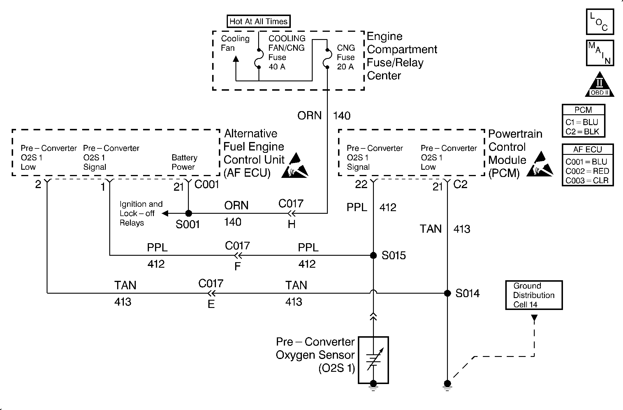
Circuit Description
In order to provide the best possible combination of driveability, fuel economy, and emission control, the vehicle uses a Closed Loop fuel metering system. While in Closed Loop, the ECU monitors the oxygen sensor signal voltage. The ECU adjusts the fuel delivery based on this voltage. The long and short term fuel values indicate a change made to the fuel delivery. If an excessively rich condition is detected with fuel trim at the limit, the ECU set DTC 56.
This is a type B DTC.
Conditions for Setting the DTC
| • | The vehicle is in CNG operation mode. |
| • | The ECT is greater than 85°C (185°F). |
| • | A rich condition exists. |
Action Taken When the DTC Sets
The ECU will set a DTC 56 and turn ON the MIL after two consecutive driving cycles with the fault active.
Conditions for Clearing the MIL/DTC
The ECU turns the MIL off after three consecutive ignition cycles without a fault condition present. A DTC will clear if no fault conditions have been detected for 40 warm-up cycles (coolant temperature has risen 40°C (72°F) from the start-up coolant temperature and the engine coolant temperature exceeds 70°C (160°F) during that same ignition cycle) or the code clearing procedure has been used.
Diagnostic Aids
Always diagnose ANY PCM codes that are present before beginning this diagnostic procedure.
If present, diagnose and correct any ECU DTCs pertaining to the O2 sensor, the MAP sensor and the gas mass sensor (GMS) before attempting to diagnose DTC 56.
Any condition that results in rich fueling can cause DTC 56 to set.
Inspect for the following conditions:
| • | MAP sensor DTCs and wiring problems. |
| • | O2 sensor DTCs and wiring problems. |
| • | Vacuum leaks. |
| • | Air leaks in the exhaust system. |
| • | A malfunctioning EVAP system. |
| • | Inspect the harness for the following conditions: |
| - | Backed out terminals |
| - | Improper mating |
| - | Broken locks |
| - | Improperly formed or damaged terminals |
| - | Poor terminal to wire connection |
| - | Damaged harness |
Test Description
The number(s) below refer to the step number(s) on the diagnostic table.
-
This step visually and physically inspects the items that can cause a rich condition.
-
This step inspects the MAP sensor and the O2 sensor faults by operating the vehicle on gasoline and interrogating the PCM for DTCs.
-
This step inspects for a short to power or a high resistance O2 signal circuit.
-
This step will verify the condition of the MAP sensor circuit. If the readings are different, the circuit is damaged or has high resistance.
-
This step will verify the condition of the ECT sensor circuit. If the readings are different, the circuit is damaged or has high resistance.
-
This step will verify the condition of the IAT sensor circuit. If the readings are different, the circuit is damaged or has high resistance.
Step | Action | Value(s) | Yes | No | ||||||||||||
|---|---|---|---|---|---|---|---|---|---|---|---|---|---|---|---|---|
1 | Was the AF Powertrain OBD System Check performed? | -- | Go to Step 2 | Go to Alternative Fuels (AF) Powertrain On Board (OBD) System Check | ||||||||||||
2 | Are any component-related DTCs set? | -- | Go to component DTC tables | Go to Step 3 | ||||||||||||
Visually and physically inspect the following items:
Was a repair necessary? | -- | Go to Step 15 | Go to Step 4 | |||||||||||||
4 | Perform the AF fuel system diagnosis. Refer to Fuel System Diagnosis . Was a problem found and repaired? | -- | Go to Step 15 | Go to Step 5 | ||||||||||||
5 |
Did the table isolate a problem requiring repair? | -- | Go to Step 15 | Go to Step 6 | ||||||||||||
Were any PCM DTCs set? | -- | Go to the applicable PCM DTC table | Go to Step 7 | |||||||||||||
Was a problem found? | 1.0 ohms | Go to Step 13 | Go to Step 8 | |||||||||||||
8 |
Was there silicon contamination present? | -- | Go to Step 15 | Go to Step 9 | ||||||||||||
9 |
Is the MAP sensor voltage within the typical scan tool data, plus or minus the specified value BARO reading normal for your altitude? | 0.4 V | Go to Step 10 | |||||||||||||
Are the readings close? | -- | Go to Step 11 | Go to Step 13 | |||||||||||||
Are the readings close? | -- | Go to Step 12 | Go to Step 13 | |||||||||||||
Are the readings close? | -- | Go to Step 14 | Go to Step 13 | |||||||||||||
13 | Repair the circuit as necessary. Refer to Wiring Repairs in Engine Controls - 2.2L in the J Platform Service Manual. Is the repair complete? | -- | Go to Step 15 | -- | ||||||||||||
14 | Replace the GMS/MCV. Refer to Gas Mass Sensor/Mixture Control Valve Replacement . Is the action complete? | -- | Go to Step 15 | -- | ||||||||||||
15 |
Did the MIL illuminate and the DTC set? | -- | Go to Step 3 | Go to Step 16 | ||||||||||||
16 | Are any ECU or PCM DTCs displayed that have not been diagnosed? | -- | Go to the applicable DTC table | System OK |
