FRONT-REAR BUMPER ADJ. FOR IMPROVED FILLER PANEL APPEAR.

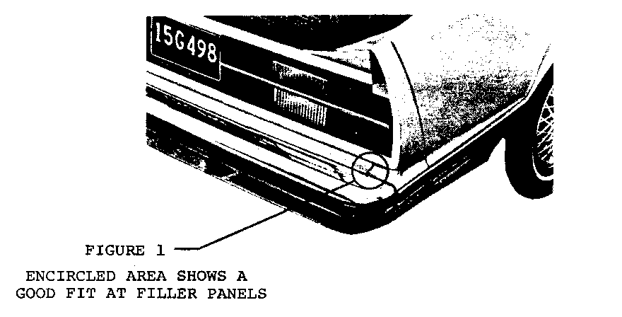
Some 1982 Celebrity style vehicles have a poor fit or match of the bumper outer filler panel and the bumper center filler panel. The encircled area on Figure 1 below shows a good fit at this location at the rear bumper:
A mis-match of the outer filler and center filler panels can occur at the front bumper and/or rear bumper. To correct the mis-match, the bumper needs to be adjusted "fore and aft" and/or "up and down".
The adjustment of the front bumper system and rear bumper system can be accomplished as follows:
FRONT BUMPER SYSTEM
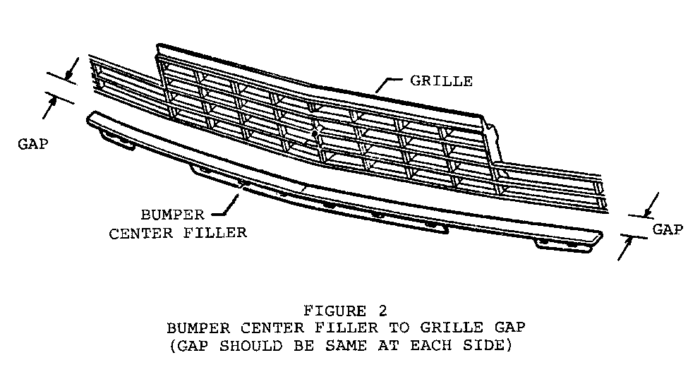
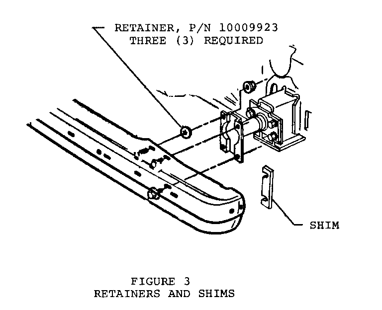
(1) Bumper is to be positioned fore-aft to obtain a consistent line across car at the bumper center filler to lower edge of grille (see Figure 2). This may require the addition of shims between the bumper and energy absorber shock (P/N 14058877 shims 1.5mm thick). Fore-aft position of bumper after shimming is not to exceed 3.0mm L.H. to R.H. side and 6.0mm at any one side. Early production vehicles normally require two (2) shims at the right front bumper attachment.
NOTICE: If more than four (4) shims are used at the same location, three (3) longer bolts (P/N 10021801) and three (3) bolt retainers (P/N 10009923) will be required. The retainers prevent the bolts from turning while tightening the nuts. See Figure 3.
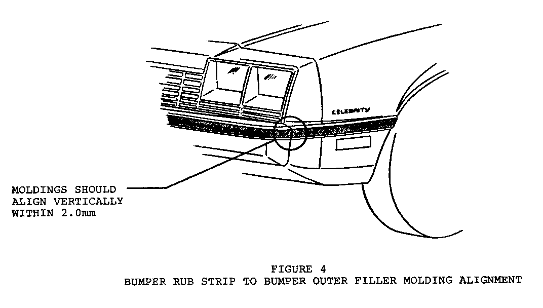
(2) The vertical position of the bumper is to be obtained by lining-up the bumper rub strip with the front bumper outer filler molding, both sides. This should result in a consistent gap between the top bumper center filler to grille of 18mm to 20mm, and the molding section on the outer filler should align with the bumper strip within 2.0mm vertically.
(3) Center bumper assembly between outer filler panels within 2.5mm to insure filler to bumper interface (design has 2.5mm interference per side).
REAR BUMPER SYSTEM
(1) Loosen energy absorber attachments to bumper and totally remove bumper and energy absorber shock sub-assembly from the body.
(2) Elongate the energy absorber to body holes in the vertical direction but maintain 2.0mm between the top holes and edge of energy absorber mounting flange. This should allow the bumper to be lowered 3.0mm to 4.0mm.
(3) Reinstall energy absorber units and loosened bumper sub-assembly to body and position. The bumper is to be positioned vertically by lining-up the bumper rub strip with the molding in the outer filler panel within 2.0mm. See Figure 4.
(4) Bumper is to be positioned fore-aft to obtain a consistent step (within 3.0mm) right to left sides of the bumper center filler rearward to the outer filler edge. This may require the use of shims between the bumper and energy absorber shock (P/N 14058879 shims 1.5mm thick). Fore-aft position of bumper after shimming is not to exceed 3.0mm L.H. to R.H. side and 6.0mm at any one side. Early production vehicles normally require four (4) shims at the L.H. side only.
NOTICE: If more than four (4) shims are used at the same location, four (4) longer bolts (P/N 10021801) will be required. Bolt retainers will not be required for the rear bumper.
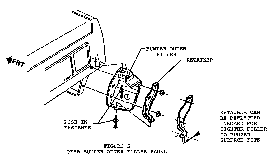
(5) To obtain a tight outer filler to bumper surface fit, remove push-in fastener at rear filler attachment to metal retainer, deflect retainer inboard and reinstall push-in fastener. Refer to Figure 5.
Labor Time Operation Number
To align front bumper = .3 Hrs. T1074
To align rear bumper = .6 Hrs. T1075
Add: To install longer bolts
Front .3 Hrs.
Back .3 Hrs.
General Motors bulletins are intended for use by professional technicians, not a "do-it-yourselfer". They are written to inform those technicians of conditions that may occur on some vehicles, or to provide information that could assist in the proper service of a vehicle. Properly trained technicians have the equipment, tools, safety instructions and know-how to do a job properly and safely. If a condition is described, do not assume that the bulletin applies to your vehicle, or that your vehicle will have that condition. See a General Motors dealer servicing your brand of General Motors vehicle for information on whether your vehicle may benefit from the information.
