INTERMITTENT ENGINE ROUGHNESS WHEN OPERATING ACCESSORIES

A momentary engine roughness may occur on subject vehicles when electrical accessories are operated (i.e., power windows, power seats, power door locks, headlamp door operation on "F" series, etc.).
The momentary roughness is probably due to a sudden voltage spike during the operation of the above mentioned accessories. This voltage spike is misinterpreted by the ECM, which may cause a momentary interruption in fuel delivery.
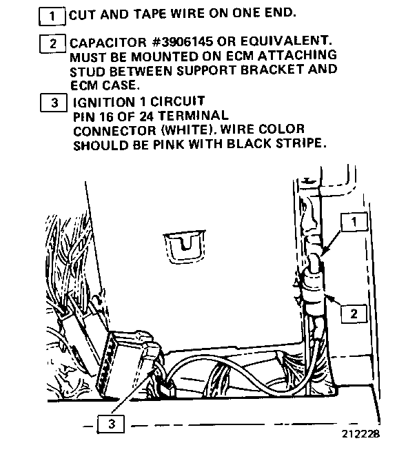
To eliminate the possibility of a voltage spike affecting proper ECM operation, a .50 MFD capacitor is to be installed on the ignition one circuit to the ECM (pin 16 of 24 way connector, pink wire with black stripe). Capacitor (P/N 3906145) is available from WDDGM and may be used for this operation.
Install the capacitor by splicing a lead of the capacitor into the ignition one circuit at the ECM 24 way connector. A "Scotch-Lok" connector or equivalent should be used. The other lead of the capacitor may be cut and taped to insure against grounding. It is important to mount the capacitor body against the ECM case. It is recommended the capacitor be mounted on the ECM attaching stud, between the support bracket and ECM case (refer to Figure 1 for mounting).
CAPACITOR INSTALLATION PROCEDURE (SEE FIGURE 1)
(1) Insure ignition switch is in "OFF" position.
(2) Remove battery voltage to ECM by disconnecting pigtail from positive battery cable.
(3) Obtain access to ECM. On "X" series open glove compartment, press inward on spring slips mounted to the side of glove compartment, allowing complete assembly to fall forward. On "A" and "F" series, it will be necessary to remove right side hush panel.
(4) Disconnect white, 24 way connector from ECM.
(5) Splice capacitor wire into ignition one circuit (pin 16, pink with black stripe) using "Scotch-Lok" or equivalent. Allow enough lead on capacitor to allow mounting on ECM attaching stud. Make certain "Scotch-Lok" penetrates insulation and makes contact with capacitor lead.
(6) Loosen ECM attaching nuts and mount capacitor BETWEEN support bracket and ECM case.
(7) Tighten attaching nuts and reconnect white ECM connector.
(8) Reinstall hush panel on "A" and "F" series. On "X" series, close glove compartment.
(9) Reconnect ECM pigtail to positive battery cable.
NOTICE: A loss of vehicle performance may be noticed when first driving vehicle. Performance will return after driving vehicle a few miles allowing ECM to "re-learn".
WARRANTY INFORMATION
Labor Operation: T0048
Time Allowance : .3 Hours

General Motors bulletins are intended for use by professional technicians, not a "do-it-yourselfer". They are written to inform those technicians of conditions that may occur on some vehicles, or to provide information that could assist in the proper service of a vehicle. Properly trained technicians have the equipment, tools, safety instructions and know-how to do a job properly and safely. If a condition is described, do not assume that the bulletin applies to your vehicle, or that your vehicle will have that condition. See a General Motors dealer servicing your brand of General Motors vehicle for information on whether your vehicle may benefit from the information.
