Removal Procedure
Important:
| • | Remove components in order to provide clearance for transmission
removal, if necessary. |
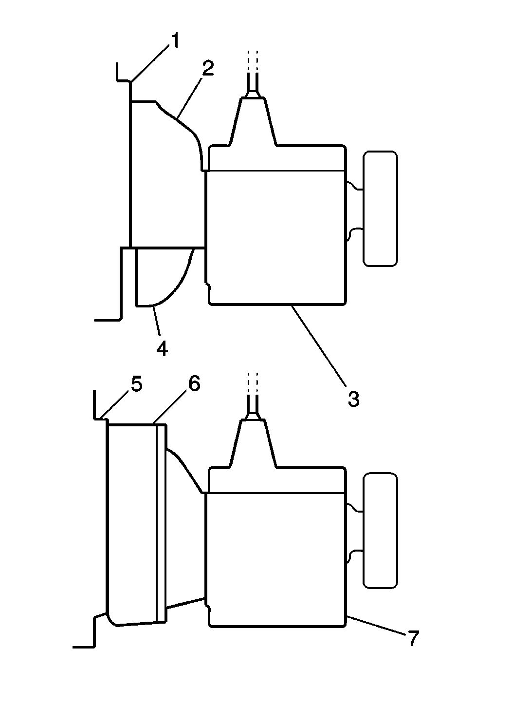
| • | The vehicles have either an apron clutch housing (2) or an SAE
number 2 (6) type flywheel housing. |
| • | The apron-type clutch has a sheet metal pan which covers the entire
lower portion of the clutch and flywheel. The clutch housing is not separate. |
| • | The SAE number 2 type flywheel housing also surrounds the flywheel.
The SAE number 2 type flywheel housing uses a separate clutch housing. Transmission
replacement procedures are different for each type of flywheel housing. |
- Block the wheels of the vehicle.
Caution: Unless directed otherwise, the ignition and start switch must be in the OFF or LOCK position, and all electrical loads must be OFF before servicing
any electrical component. Disconnect the negative battery cable to prevent an electrical spark should a tool or equipment come in contact with an exposed electrical terminal. Failure to follow these precautions may result in personal injury and/or damage to
the vehicle or its components.
- Disconnect
the negative battery cable.
Important: Before you disconnect any air operated components or air lines, bleed
all air pressure from the system.
Check what type of front engine mount is used. If a single cushion center
mount is used, support the engine with an overhead hoist during transmission
or clutch replacement.
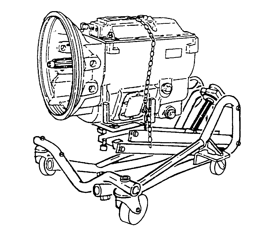
Important: When removing or installing the transmission, use a transmission dolly
jack in order to support the weight of the transmission. Fasten a safety chain
over the top of the transmission and to both sides of the dolly.
- Shift the transmission into neutral.
- Remove the air shift controls from the shift lever. Refer to
Air Shift Control Valve Replacement
.
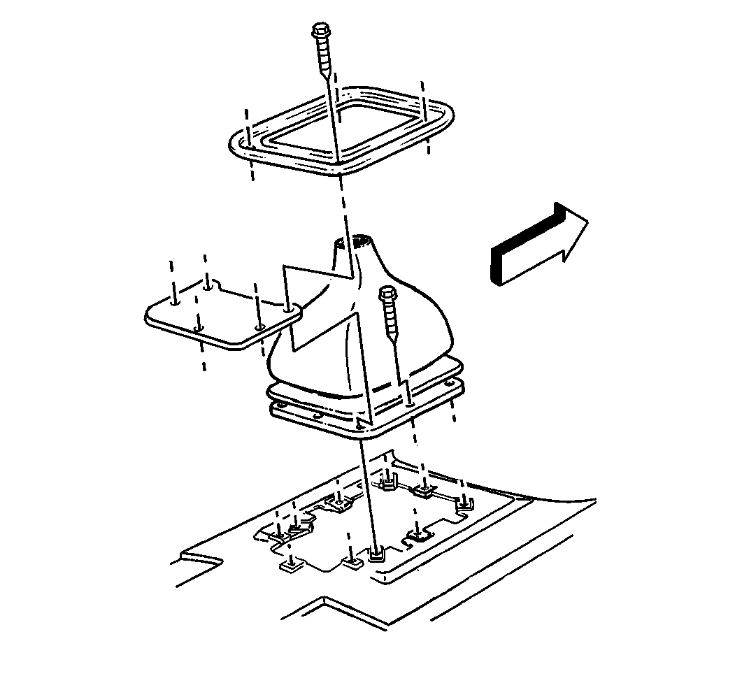
- Remove the screws from
the shift lever boot retainer.
- Remove the retainer from the shift boot.
- Remove the shift boot.
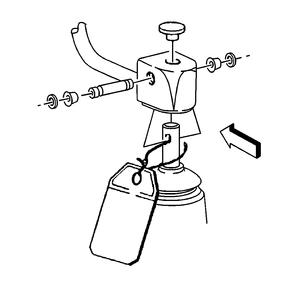
- For the 7.0 L and 6.0 L
engines, remove the shift lever.
- Remove the clutch cable from the transmission. Refer to
Clutch Assembly Adjustment
.
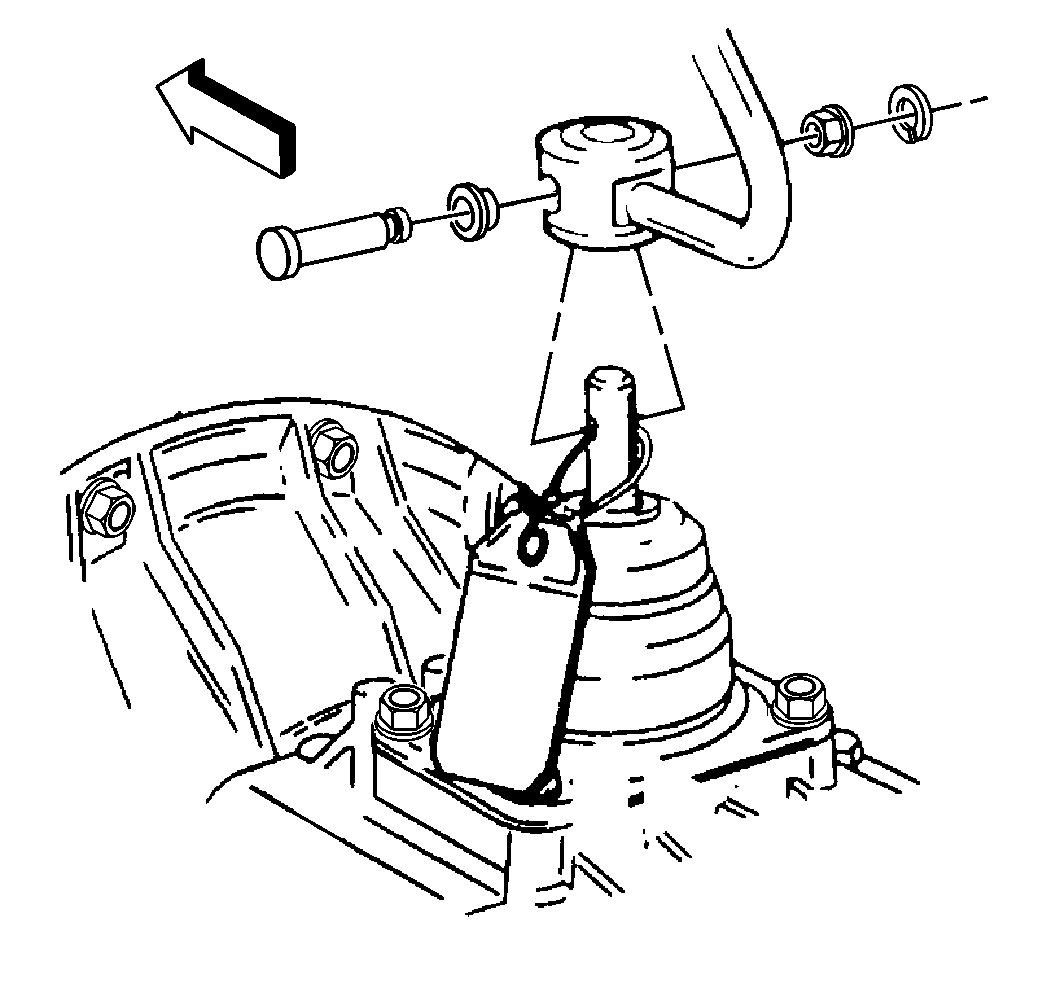
- Remove the following components
from the shift control lever:
- Remove the electric connectors, as necessary.
- Remove the air lines from the air shift control valve.
- Remove the oil from the transmission. Refer to
Transmission Oil Changing
.
- Remove the muffler, if required. Refer to
Exhaust System Replacement
.
- Remove the parking brake lever and controls, if used. Refer to
Park Brake Cable Replacement
in Park Brake.
- Remove the propeller shaft. Refer to the proper procedure:
- Remove the power take-off and controls, if used.
| • | Place a protective cover over the opening. |
| • | Position a transmission dolly jack under the vehicle. Adjust the
dolly jack in order to carry the weight of the transmission. |
- Remove the rear support beam, if used.
Notice: When removing the transmission, do not allow the weight of the transmission
to hang on the clutch disc hub. The clutch disc will become distorted and
seriously affect the operation of the clutch.
- In order to remove the transmission from the engine (SAE number 2 flywheel
housing), perform the following procedure :
| 19.1. | If the engine rear mounting is attached to the transmission, support
the engine weight with a hoist or jack. |
| 19.3. | Adjust the transmission dolly in order to support the transmission's
weight. |
| 19.4. | Remove all bolts attaching the clutch housing to the engine flywheel
housing. |
| 19.5. | Move the transmission straight back from the engine. Keep the
mainshaft in alignment with the clutch disc hub. |
| 19.6. | When the transmission is free from the engine, lower and remove
the transmission from beneath the vehicle. |
- In order to remove the transmission from the engine (Apron-type
flywheel housing), perform the following procedure:
| 20.1. | Remove the cover from the bottom of the clutch housing (optional). |
| 20.2. | Remove the lower transmission to flywheel housing bolts from the
clutch housing. |
| 20.3. | Remove the remaining upper attaching bolts. |
| 20.4. | Move the transmission straight back from the engine. Keep the
transmission mainshaft in alignment with the clutch disc hub. |
| 20.5. | When the transmission is free from the engine, lower and remove
the transmission from the vehicle. |
Installation Procedure
- Shift the transmission into high gear.

- Mount the transmission
on a suitable dolly and move the transmission into position under the vehicle.
- Rotate the output flange or yoke to align the main drive gear
shaft with the clutch disc hub.
Notice: When removing the transmission, do not allow the weight of the transmission
to hang on the clutch disc hub. The clutch disc will become distorted and
seriously affect the operation of the clutch.
- Move the transmission forward, guiding the main drive gear shaft into
the clutch disc splines.
| • | Avoid springing the clutch when you install the transmission. |
| • | Do not let the transmission drop or hang unsupported in the splined
hub of the clutch disc. |
Notice: Use the correct fastener in the correct location. Replacement fasteners
must be the correct part number for that application. Fasteners requiring
replacement or fasteners requiring the use of thread locking compound or sealant
are identified in the service procedure. Do not use paints, lubricants, or
corrosion inhibitors on fasteners or fastener joint surfaces unless specified.
These coatings affect fastener torque and joint clamping force and may damage
the fastener. Use the correct tightening sequence and specifications when
installing fasteners in order to avoid damage to parts and systems.
- In order to install
2 type flywheel housing, install the bolts and washers that attach the transmission
clutch housing to the transmission flywheel housing.
Tighten
Tighten all the attaching bolts to 44 N·m (32 lb ft).
- In order to install apron type flywheel housing, perform the following
steps:
| 6.1. | Install the upper bolts and washers that attach the transmission
to the flywheel housing. |
| 6.2. | Install the lower bolts and washers that attach the transmission
to the flywheel housing. |
Tighten
Tighten all the attaching bolts to 142 N·m (105 lb ft).
| 6.3. | Install the rear support beam, if used. |
| 6.4. | Measure the space between the outer ends of the support beam and
cushion assembly. |
| 6.5. | Select spacers equal to this gap. |
| 6.6. | If there is a difference in the gap between the left and right
sides of the rear mounting, measure the total gap between the left and the
right sides and divide by two. |
- Install the power take-off and the controls, if used.
- Install the propeller shaft. Refer to the proper procedure:
- Install the parking brake lever and the controls, if used. Refer
to
Park Brake Lever Assembly Replacement
in Brakes.
- Install the clutch cable. Refer to
Clutch Assembly Adjustment
.
- Install the muffler, as necessary. Refer to
Exhaust System Replacement
- Install the electrical connectors, as necessary.
- Install the air lines to the transmission, as used.

- For the 7.0 L and
6.0 L engines, install the shift lever.

- Install the following
components to the control lever:
| • | Apply a small amount of grease around the pin prior to installation. |

- Install the retainer to
the shift boot with screws.
- Install the air shift controls to the shift lever. Refer to
Air Shift Control Valve Replacement
.
- Fill the transmission with transmission oil. Refer to
Transmission Oil Changing
.
- Install the parking brake, if used. Refer to
Park Brake Cable Replacement
in Park Brake.
- Install the clutch cable. Refer to
Clutch Assembly Adjustment
.


