Steering Knuckle and King Pin Replacement Without FH4
Removal Procedure
Tools Required
| • | J 35999 Tension Scale |
| • | J 39758 King Pin Holding Tool |
- Set the parking brake.
- Block the vehicle rear wheels.
- Raise the front of the vehicle until the tires clear the floor.
- Support the frame using suitable safety stands.
- Remove the front wheels. Refer to Front Wheel Hub, Bearing, and Seal Replacement .
- Remove the brake components as needed. Refer to Brake Caliper Replacement .
- Remove the brake backing plates and the dust covers.
- Remove the tie rod arm bolts (9). Lower the tie rod arm (10) and the tie rod to the floor.
- Remove the steering arm bolts (5). Support the steering arm (6) and the steering rod out of the way.
- Remove the king pin upper cap (1).
- Remove the following components:
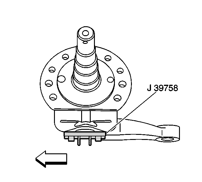
- Using J 39758 , insert the tool pins into the holes at the bottom of the king pin. Align the tools bolt holes and secure with two bolts into the steering knuckle. This prevents the king pin from spinning.
- Remove the king pin nut (2).
- Remove the king pin (12) by knocking out the pin with a soft-faced mallet.
- Remove the steering knuckle (20).
- Remove the following components from the knuckle (20):
- Remove the king pin bushing (13), if required. Refer to King Pin Bushing and Bearing Cup Replacement .
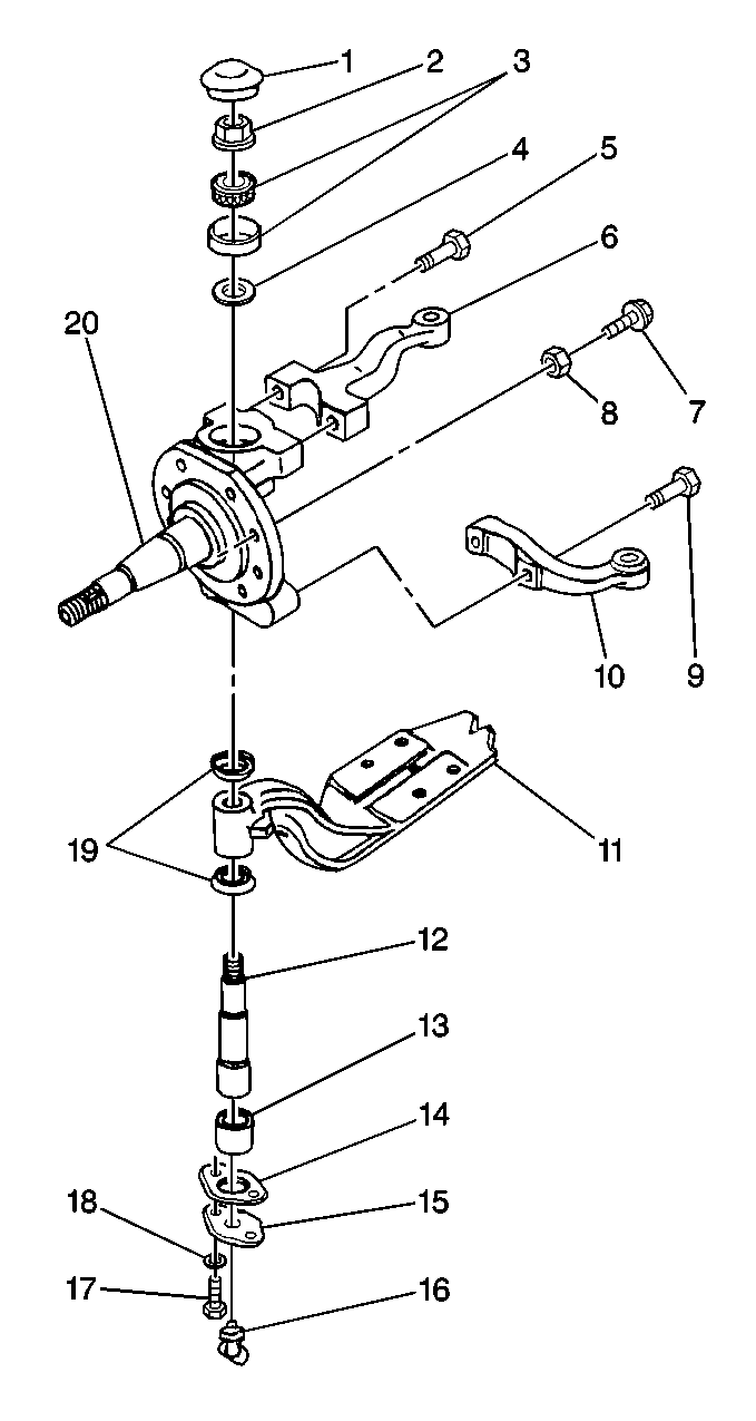
| • | The bolts (17) |
| • | The washers (18) |
| • | The king pin lower cap (15) |
| • | The gasket (14) |

| • | The seals (19) |
| • | The bearing (3) |
| • | The shim or spacer (4) |
| • | The bushing (13) |
Inspection Procedure
- Clean the axle components using a cleaning solvent.
- Soak the thrust bearing until all of the old lubricant is gone.
- Inspect the axle components for the following conditions:
- Use Magna-Flux™ inspection, if available, in order to inspect the steering knuckle (20) and the kingpins (12) for minute cracks, checks, or fractures.
- Inspect the thrust bearings and the cups for rough rotation.
- Inspect the axle king pin (12) bores for the following conditions:
- Inspect the king pin bushing (13) bores for the following conditions:
- Smooth the bore using a crocus cloth or a fine grit sandpaper if needed. Clean the bore.

| • | Wear |
| • | Pitting |
| • | Cracks |
| • | Damage |
| • | Scratches |
| • | Burrs |
| • | Corrosion |
| • | Scratches |
| • | Burrs |
| • | Corrosion |
Installation Procedure
- Install the king pin bushings (13), if removed.
- Install the king pin bearing cup, if removed.
- Install the steering knuckle (20).
- Install the king pin (12). Install the dust seals (19).
- Install a shim or spacer (4).
- Install the king pin thrust bearing (3). Pack the bearing thoroughly with high temperature wheel bearing grease.
- Install the king pin nut (2).
- Using J 39758 insert the tool pins into the holes at the bottom of the king pin.
- Align the tool's bolt holes.
- Secure the tool with two bolts into the steering knuckle in order to keep the king pin from spinning.
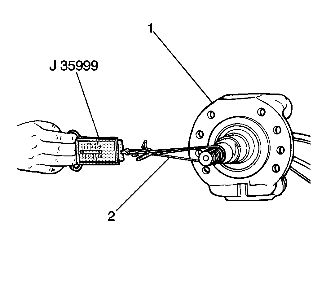
- Measure the king pin bearing preload using the J-35999. Refer to King Pin Bearing Preload .
- Install the following components:
- Install the king pin upper dust cap (1). Tap into place with a soft-faced mallet. Grease the knuckle (19) through the lubrication fitting (16) on the bottom.
- Install the tie rod arm (10).
- Install the steering arm (6), if removed.
- Install the brake backing plate and the dust cover.
- Install the brake components as needed. Refer to Brake Caliper Replacement .
- Install the front wheels. Refer to Front Wheel Hub, Bearing, and Seal Replacement .
- Remove the safety stands and lower the vehicle.
- Check the axle alignment.
- Check the stop screw (7, 8) adjustment. Adjust as needed. Refer to Stop Screw Adjustment in Wheel Alignment.


Notice: Use the correct fastener in the correct location. Replacement fasteners must be the correct part number for that application. Fasteners requiring replacement or fasteners requiring the use of thread locking compound or sealant are identified in the service procedure. Do not use paints, lubricants, or corrosion inhibitors on fasteners or fastener joint surfaces unless specified. These coatings affect fastener torque and joint clamping force and may damage the fastener. Use the correct tightening sequence and specifications when installing fasteners in order to avoid damage to parts and systems.
Tighten
Tighten the king pin nut (2) to 550 N·m (406 lb ft).

| • | The bottom gasket (14) |
| • | The dust cap (15) |
| • | The flat washers (18) |
| • | The bolts (17) |
Tighten
Tighten the dust cap bolt to 24 N·m (18 lb ft).
Steering Knuckle and King Pin Replacement With FH4 16,000 lb
Tools Required
J 8001 Dial Indicator Set
Knuckle Vertical Play Inspection
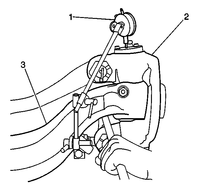
- Prior to performing inspections, the following preliminary steps should be accomplished.
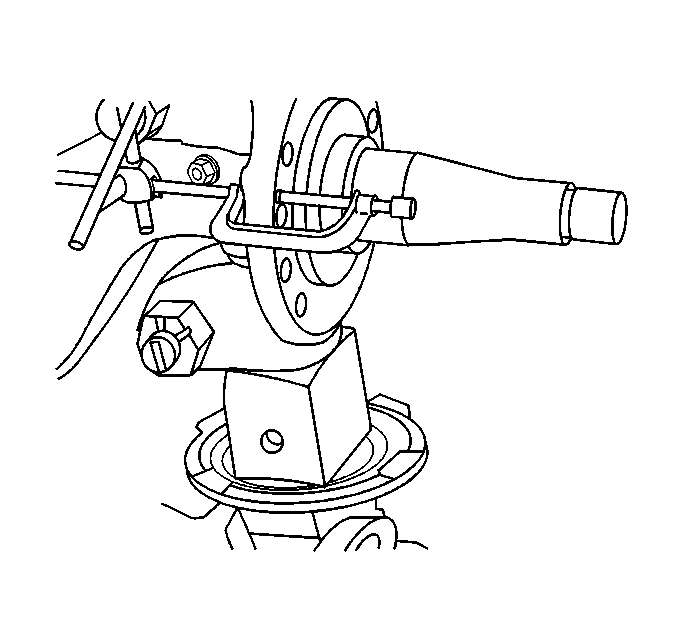
- Mount dial indicator (1) on axle beam (3). Reference the knuckle cap.
- Pry steering knuckle downward (2).
- Zero the dial indicator (1).
- Lower the front axle (3) to obtain the indicator reading. If reading exceeds 1.02 mm (0.040 in) , inspect thrust bearings. Replace if necessary and adjust.
| 1.1. | Set the parking brake. |
| 1.2. | Block the vehicle rear wheels. |
| 1.3. | Raise the front of the vehicle until the tires clear the floor. |
| 1.4. | Support the frame using suitable safety stands. |
| Important: Inspection procedures assumes axle is assembled and installed in vehicle with tire and wheels. Checking knuckle vertical play during axle assemble requires different procedure. |
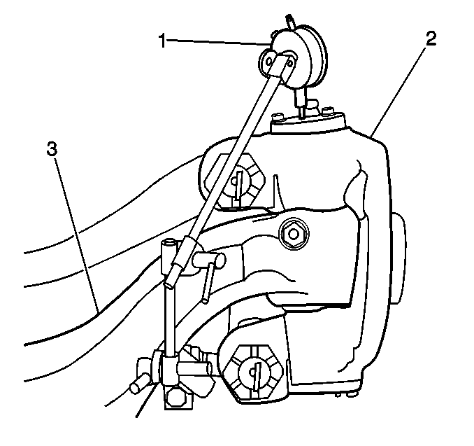
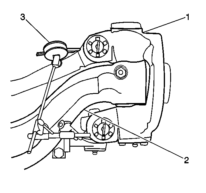
Knuckle Pin Fit Inspection/Upper
- Mount a dial indicator (3) on the axle (2) as shown. Reference upper part of knuckle.
- Move top of wheel in and out with a push/pull motion. Have assistant monitor the dial indicator.
- Readings in excess of 0.015 in (0.38 mm) indicate the need for bushing replacement.
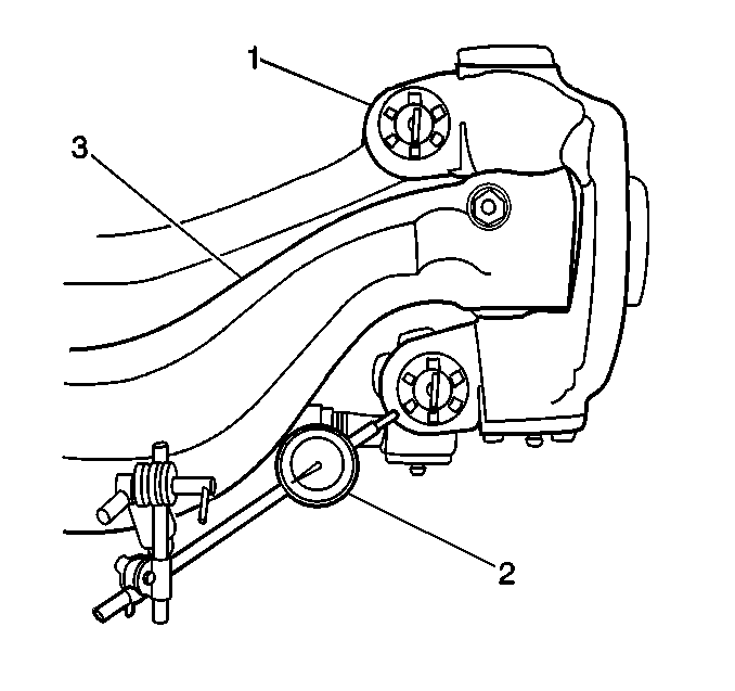
Knuckle Pin Fit Inspection/Lower
- Mount dial indicator (2) on the axle (3) . Reference the lower Ackermann Arm socket of the steering knuckle (1).
- Move bottom of wheel in and out with a push/pull motion. Have assistant read dial indicator.
- Dial indicator readings in excess of 0.015 in (0.38 mm) indicate that the lower bushing should be replaced.
Removal Procedure
- Set the parking brake.
- Block the vehicle rear wheels.
- Raise the front of the vehicle until the tires clear the floor.
- Support the frame using suitable safety stands.
- Remove the following components as needed. Refer to Brake Drum Replacement in Front Brake Drum Replacement.
- Remove the brake components as needed. Refer to Brake Drum Replacement in Front Brake Drum Replacement.
- Remove the cotter pin from the tie rod ball joint.
- Remove the nut (5) from the drag link steering arm.
- Disconnect the drag link from the steering arm.
- Remove the following components:
- Remove the draw key (3) from axle using a hammer and a brass drift.
- Remove the knuckle pin (13) by knocking out with a hammer and a brass drift.
- Remove the steering knuckle (14).
- Remove the following components from the knuckle:
- Remove the king pin bushings (12) using a piloted drift tool.
- Discard the thrust bearing (4).
| • | The wheels |
| • | The hubs |
| • | The bearings |
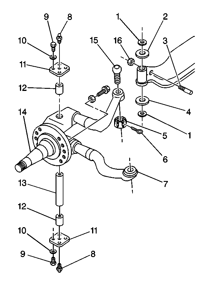
| • | The cap screws (9) |
| • | The lockwashers (10) |
| • | The upper and lower knuckle caps (11) |
| Important: Do not use heat on any parts or fasteners. |
| • | Remove nut (16) from the draw key (3). |
| • | The seals (1) |
| • | The thrust bearing (4) |
| • | The shims (2) |
Inspection Procedure
- Clean the axle components using a cleaning solvent.
- Inspect the axle components for the following conditions:
- Use Magna-Flux™ inspection, if available, in order to inspect the steering knuckle (14) and the kingpins (13) for minute cracks, checks, or fractures.
- Inspect the axle king pin (13) bores for the following conditions:
- Inspect the king pin bushing bores for the following conditions:
- Smooth the bore using a crocus cloth or a fine grit sandpaper if needed. Clean the bore.

| • | Wear |
| • | Pitting |
| • | Cracks |
| • | Damage |
| • | Scratches |
| • | Burrs |
| • | Corrosion |
| • | Scratches |
| • | Burrs |
| • | Corrosion |
Installation Procedure
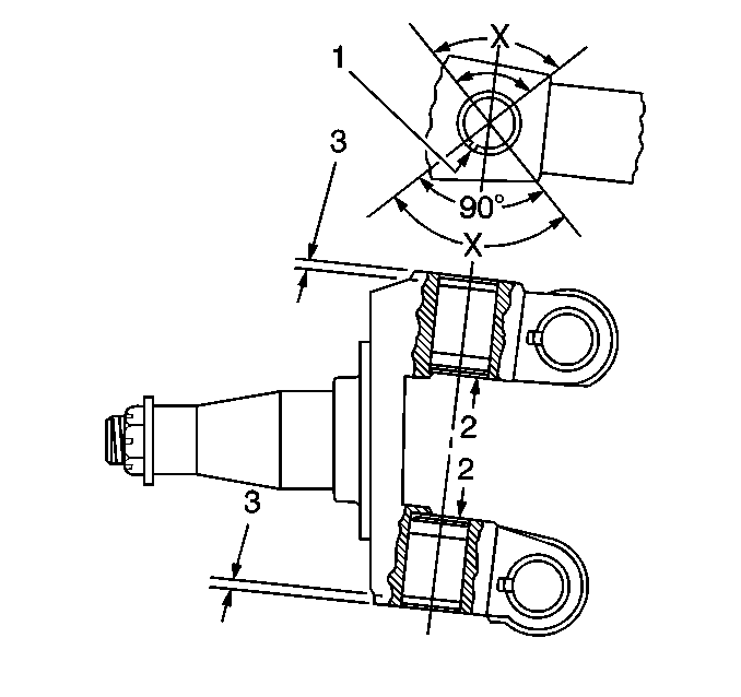
- Install the king pin bushings (2) noting the bushing position (1).
- Install new grease seals.
- Lightly lubricate (1) the following components:
- Position the thrust bearing (4) on the knuckle (14).
- Install the knuckle (14) to the axle beam.
- Install shims (2) at knuckle (14) upper end to remove vertical end play.
- Install pin (13) in knuckle (14) and axle from the top.
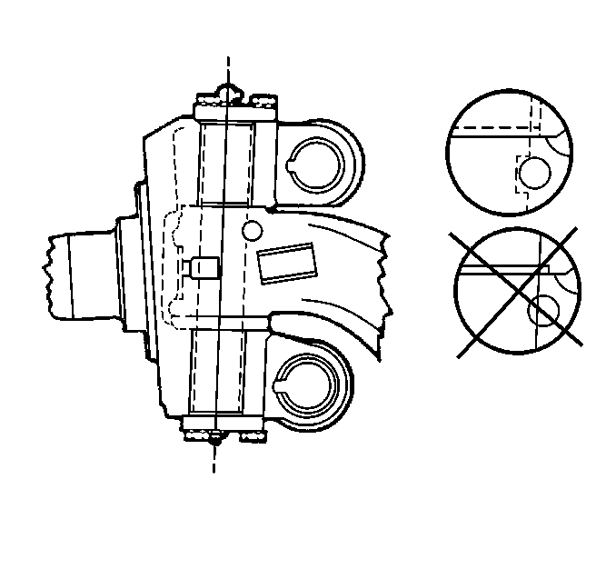
- Align the flat of the knuckle pin (13) with the draw key hole.
- Install shims (2) at knuckle upper end to remove vertical end play.
- Check knuckle vertical play and adjust .
- Check knuckle vertical play using a dial indicator. Reference dial indicator at top of knuckle pin.
- Simulate axle loading with a jack and note dial indicator reading.
- Add or remove shims as necessary to obtain correct vertical end play.
- Install a new draw key.
- Align the draw key hole with the knuckle pin flat.
- Install draw key nut (16).
- Apply silicone rubber gasket compound to knuckle (14) cap mounting surface.
- Install the knuckle king pin caps (11).
- Install the lockwashers (11).
- Install the cap screws (9).
- Install the drag link to the steering arm.
- Install the nut (5).
- Install the cotter pin (6).
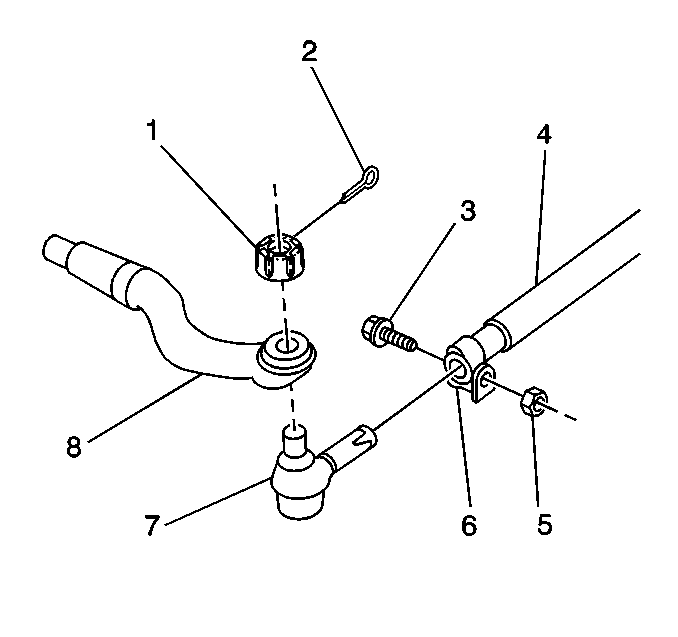
- Install the tie rod ball joint (7) to the Ackermann arm (8).
- Install the tie rod ball joint nut (1).
- Install the cotter pin (2).
- Install brake components. Refer to Brake Drum Replacement .
- Remove the safety stands and lower the vehicle.
- Check the axle alignment.
- Check the stop screw adjustment. Adjust as needed.
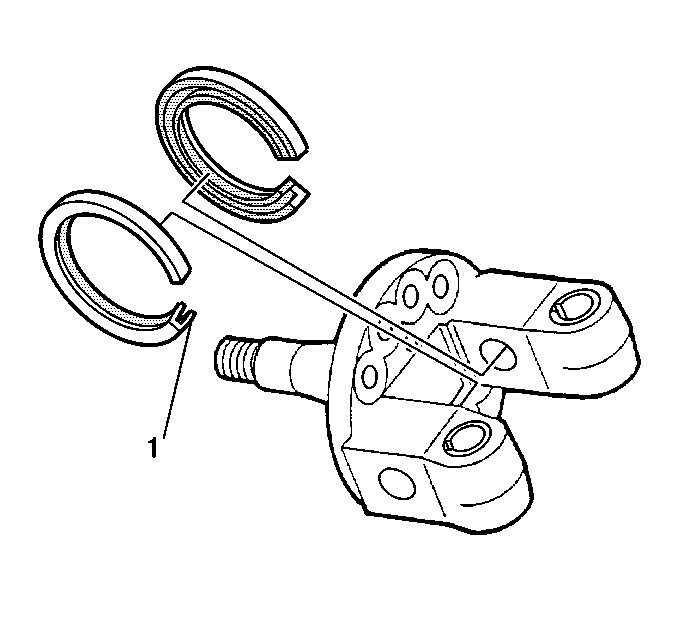
Important: When installing grease seal, be sure lip (1) is pointing toward center of knuckle.
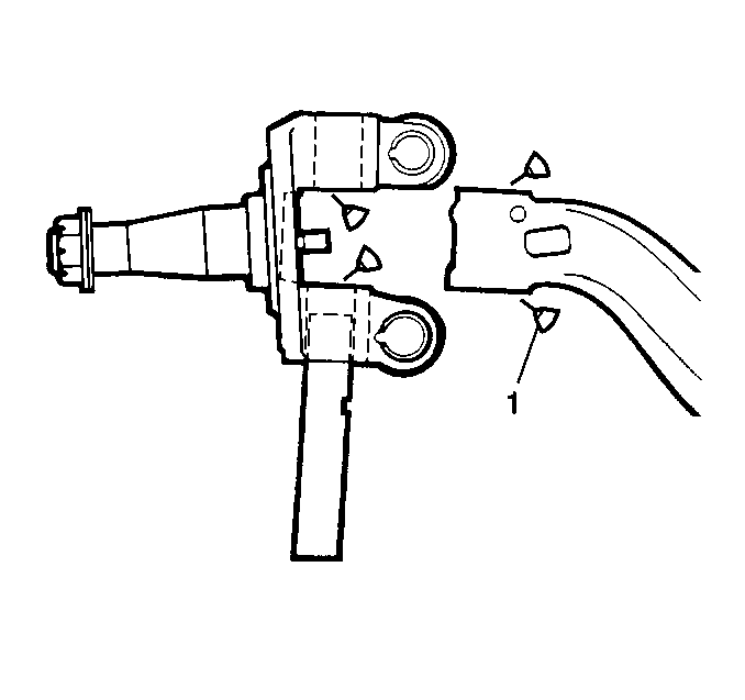
| • | The thrust bearing areas of the steering knuckle |
| • | The axle end |
| • | The knuckle pin bore of the axle beam |
| • | Pack the bushing bores with grease. |

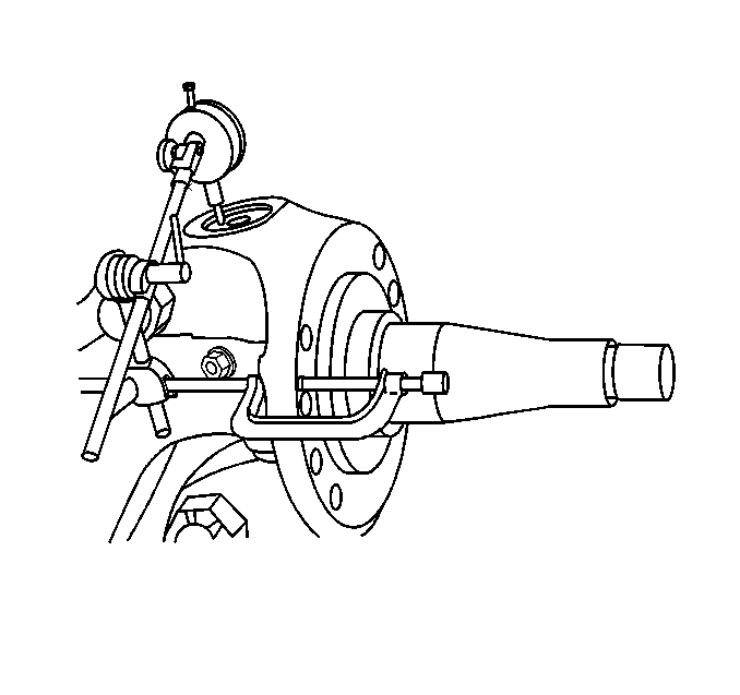
Measure
Knuckle vertical play should be 0.002 to 0.012 in (0.015 to 0.305 mm).

Notice: Use the correct fastener in the correct location. Replacement fasteners must be the correct part number for that application. Fasteners requiring replacement or fasteners requiring the use of thread locking compound or sealant are identified in the service procedure. Do not use paints, lubricants, or corrosion inhibitors on fasteners or fastener joint surfaces unless specified. These coatings affect fastener torque and joint clamping force and may damage the fastener. Use the correct tightening sequence and specifications when installing fasteners in order to avoid damage to parts and systems.
Tighten
Tighten the draw key nut to 41-61 N·m (30-45 lb ft).
Important: Do not apply excessive silicone compound which could block the grease path for the knuckle pin bushings.
Tighten
Tighten the cap screws to 30-38 N·m (22-28 lb ft).
Tighten
Tighten the nut to 224-312 N·m (165-230 lb ft).
Important: Tighten the nut to the minimum range, than tighten to align cotter pin hole. If torque exceeds the maximum range, replace the nut.
Tighten
Tighten the tie rod ball joint nut to 224-312 N·m
(165-230 lb ft).
| • | The wheel bearings |
| • | The hubs |
| • | The wheels |
Stop Screw Adjustment
Adjust the steering stops so that the power assist stops approximately
3 degree's or 3.175 mm (1/8 in) before reaching the steering stop screws.
