Purpose:
To control spark knock (detonation), a knock sensor (KS) system is used.
This system is designed to retard spark timing when excessive spark knock
is detected in the engine. The KS system allows the engine to use maximum
spark advance for optimal driveability and fuel economy under all operating
conditions.
Operation:
The PCM uses a knock sensor to detect abnormal vibration in the engine
(detonation/spark knock). Mounted on the engine block, the knock sensor produces
an AC voltage signal at all engine speeds and loads. The PCM then adjusts
the spark timing based on the amplitude and frequency of the KS signal.
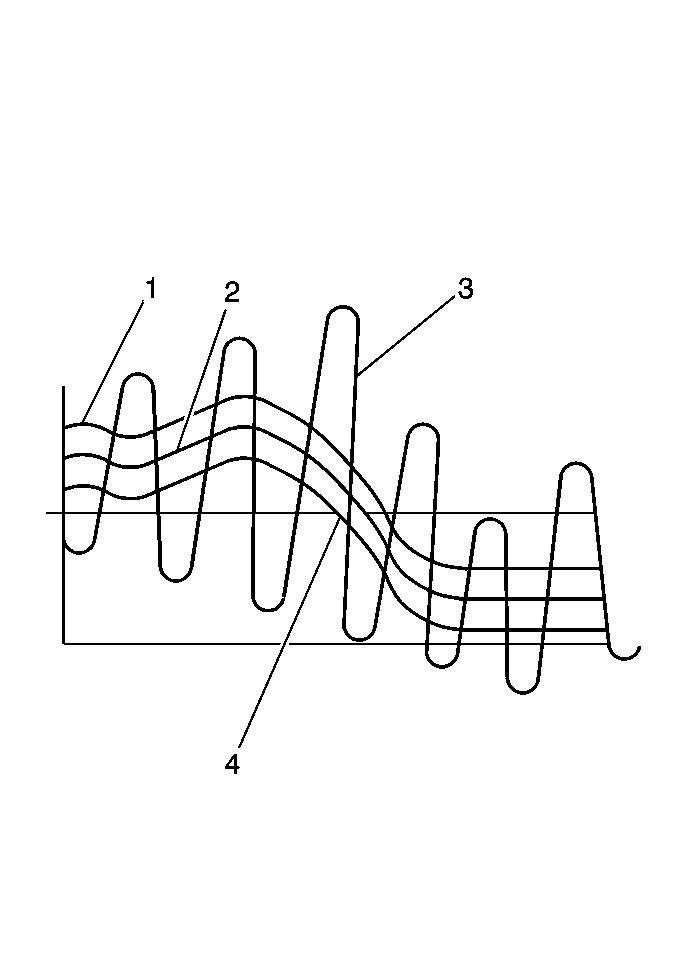
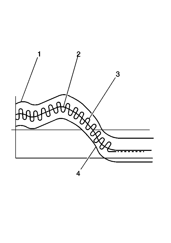
The PCM uses the KS signal to calculate an average voltage. Then, the
PCM assigns a voltage range above and below the average voltage value.
The PCM checks the KS and related wiring by comparing the actual knock signal
to the assigned voltage range. A normal KS signal should vary outside
the assigned voltage range as shown in the NORMAL KS figure. If the PCM
detects a KS signal within the assigned voltage range as shown in the
ABNORMAL figure the applicable DTC will be set.
Normal knock sensor signal

Abnormal knock sensor signal

Legend
- Upper fail region
- Knock sensor calculated average
- Knock sensor signal
- Lower fail region
Diagnosis
A diagnostic trouble code (DTC) may set for the following conditions
or faults:
| • | The PCM malfunctions in a manner which will not allow the PCM
to run a diagnostic of the KS circuit. |
| • | The KS signal is within the assigned voltage range. |
| • | The KS signal is not present. |
| • | The PCM is unable to eliminate the knocking condition using the
maximum spark retard. |


